EP1312882A2 - Installation method of fireproof structure for protecting water pipes - Google Patents
Installation method of fireproof structure for protecting water pipes Download PDFInfo
- Publication number
- EP1312882A2 EP1312882A2 EP02025279A EP02025279A EP1312882A2 EP 1312882 A2 EP1312882 A2 EP 1312882A2 EP 02025279 A EP02025279 A EP 02025279A EP 02025279 A EP02025279 A EP 02025279A EP 1312882 A2 EP1312882 A2 EP 1312882A2
- Authority
- EP
- European Patent Office
- Prior art keywords
- refractory
- water pipes
- fireproof structure
- tiles
- castable
- Prior art date
- Legal status (The legal status is an assumption and is not a legal conclusion. Google has not performed a legal analysis and makes no representation as to the accuracy of the status listed.)
- Granted
Links
Images




Classifications
-
- F—MECHANICAL ENGINEERING; LIGHTING; HEATING; WEAPONS; BLASTING
- F23—COMBUSTION APPARATUS; COMBUSTION PROCESSES
- F23M—CASINGS, LININGS, WALLS OR DOORS SPECIALLY ADAPTED FOR COMBUSTION CHAMBERS, e.g. FIREBRIDGES; DEVICES FOR DEFLECTING AIR, FLAMES OR COMBUSTION PRODUCTS IN COMBUSTION CHAMBERS; SAFETY ARRANGEMENTS SPECIALLY ADAPTED FOR COMBUSTION APPARATUS; DETAILS OF COMBUSTION CHAMBERS, NOT OTHERWISE PROVIDED FOR
- F23M5/00—Casings; Linings; Walls
- F23M5/08—Cooling thereof; Tube walls
-
- F—MECHANICAL ENGINEERING; LIGHTING; HEATING; WEAPONS; BLASTING
- F23—COMBUSTION APPARATUS; COMBUSTION PROCESSES
- F23M—CASINGS, LININGS, WALLS OR DOORS SPECIALLY ADAPTED FOR COMBUSTION CHAMBERS, e.g. FIREBRIDGES; DEVICES FOR DEFLECTING AIR, FLAMES OR COMBUSTION PRODUCTS IN COMBUSTION CHAMBERS; SAFETY ARRANGEMENTS SPECIALLY ADAPTED FOR COMBUSTION APPARATUS; DETAILS OF COMBUSTION CHAMBERS, NOT OTHERWISE PROVIDED FOR
- F23M5/00—Casings; Linings; Walls
- F23M5/04—Supports for linings
-
- F—MECHANICAL ENGINEERING; LIGHTING; HEATING; WEAPONS; BLASTING
- F23—COMBUSTION APPARATUS; COMBUSTION PROCESSES
- F23M—CASINGS, LININGS, WALLS OR DOORS SPECIALLY ADAPTED FOR COMBUSTION CHAMBERS, e.g. FIREBRIDGES; DEVICES FOR DEFLECTING AIR, FLAMES OR COMBUSTION PRODUCTS IN COMBUSTION CHAMBERS; SAFETY ARRANGEMENTS SPECIALLY ADAPTED FOR COMBUSTION APPARATUS; DETAILS OF COMBUSTION CHAMBERS, NOT OTHERWISE PROVIDED FOR
- F23M2900/00—Special features of, or arrangements for combustion chambers
- F23M2900/05004—Special materials for walls or lining
-
- F—MECHANICAL ENGINEERING; LIGHTING; HEATING; WEAPONS; BLASTING
- F27—FURNACES; KILNS; OVENS; RETORTS
- F27D—DETAILS OR ACCESSORIES OF FURNACES, KILNS, OVENS OR RETORTS, IN SO FAR AS THEY ARE OF KINDS OCCURRING IN MORE THAN ONE KIND OF FURNACE
- F27D1/00—Casings; Linings; Walls; Roofs
- F27D1/14—Supports for linings
- F27D1/141—Anchors therefor
-
- F—MECHANICAL ENGINEERING; LIGHTING; HEATING; WEAPONS; BLASTING
- F27—FURNACES; KILNS; OVENS; RETORTS
- F27D—DETAILS OR ACCESSORIES OF FURNACES, KILNS, OVENS OR RETORTS, IN SO FAR AS THEY ARE OF KINDS OCCURRING IN MORE THAN ONE KIND OF FURNACE
- F27D9/00—Cooling of furnaces or of charges therein
- F27D2009/0002—Cooling of furnaces
- F27D2009/0018—Cooling of furnaces the cooling medium passing through a pattern of tubes
- F27D2009/0032—Cooling of furnaces the cooling medium passing through a pattern of tubes integrated with refractories in a panel
-
- F—MECHANICAL ENGINEERING; LIGHTING; HEATING; WEAPONS; BLASTING
- F27—FURNACES; KILNS; OVENS; RETORTS
- F27D—DETAILS OR ACCESSORIES OF FURNACES, KILNS, OVENS OR RETORTS, IN SO FAR AS THEY ARE OF KINDS OCCURRING IN MORE THAN ONE KIND OF FURNACE
- F27D21/00—Arrangement of monitoring devices; Arrangement of safety devices
- F27D21/02—Observation or illuminating devices
Definitions
- the present invention relates to a fireproof structure that protects the walls of water pipes installed in incinerators, boilers and the like for cooling and heat exchange from the high temperature gas environment therein.
- a protective fireproof structure and method of its installation which can be implemented on water pipe walls having curves or bends.
- Water pipes are installed inside of garbage incinerators, boilers and the like to cool the high temperature gas environment or perform heat exchange, and those water pipes have been protected from not only the high temperature gas environment, but the abrasion from flying ash and corrosion by the installation of fireproof tiles or fireproof castable structures around the incinerator/furnace walls.
- Such walls of water pipes have been, for example, installed in stoker type incinerators 50 on the inside of the incinerator walls 56 as shown in Figure 9.
- Said stoker type incinerator 50 is comprised of trash inlet opening 51, grate 53, ash removal opening 45, air supply duct 55, and free board 52, and boiler water pipes are installed on incinerator wall 56 in order to recover the waste heat generated by burning.
- boiler pipes 10 which comprise water pipe wall 26. That surface is covered by refractory tiles 25, refractory block, refractory castable or other fireproof material.
- the combustion chambers of incinerators such as stoker type incinerators 50, or those in boilers and the like have a number of openings such as air duct 55, and an opening (manhole) for egress of maintenance workers to perform maintenance, and openings for the insertion of monitoring instruments such as a thermometer.
- the foregoing water pipes 10 must be installed to detour around such openings. Accordingly, there are a number of areas where water pipes 10 have a plurality of bends and lack a regularly arrayed structure, such as around the thermometer seat 24, manhole 22, monitoring instrument insertion openings, and air ducts.
- the refractory castable being amorphous, can be easily installed on site, however, the precision with which it was installed was apt to vary depending upon the skill of each worker, and its longevity was inferior to that of the fixed-shape refractories, which were pressed and fired in a factory.
- the present invention was developed to address the problems of the prior art; the objectives of this invention is to provide a fireproof structure and installation method for protecting water pipes that delivers stable longevity in high temperature environments, that is easily installed, even in areas of the water pipe wall where bends exist, and that can be inexpensively manufactured.
- this invention discloses, an installation method for a fireproof structure to protect water pipes, which protects water pipe walls installed in the bend areas in incinerators, boilers and the like from the high temperature environment, comprising: a refractory castable process to embed refractory castable in concave area between adjacent water pipes, at least in the areas where the pipes bend to create an approximately flat surface on the water pipe wall that faces the high temperature side; and a refractory tile process to install approximately flat-shaped refractory tiles over the surface of said embedded refractory castable.
- This invention by first flattening the surface with refractory castable, even in areas where the water pipes are bent and assume a complex shape such as around the air ducts, manholes for worker egress, insertion openings for monitoring instruments and a clinker chill area, etc., eliminates the need to manufacture a plurality of types of refractory tiles, thereby serving to reduce manufacturing costs and provide a simple surface over which the refractory tiles can be easily installed.
- the fireproof structure is a double-layered structure comprised of castable refractory material and refractory tiles, even if any of the refractory tiles should fall off, the water pipes remain protected by the foregoing refractory castable, to thereby prevent the pipes from being suddenly exposed.
- another preferred embodiment of the invention is characterized by the configuration wherein the process to install the flat-shaped refractory tiles, which includes a process to insert fastening members previously installed on the foregoing water pipe wall into a groove formed in said refractory tiles to hold said tiles in place; and a process to bind said refractory tiles to said embedded refractory castable by an adhesive material.
- another preferred embodiment of the invention is characterized by the configuration wherein the refractory castable is installed in a manner such that the ratio between the radius of the foregoing water pipes and the thickness of said refractory castable falls within the range of approximately 1 : 1 to 1.5.
- this ratio between the radius of the foregoing water pipes and the thickness of the refractory castable is set to approximately 1 : . , where the value of . would range from approximately 1 to 1.5, preferably approximately 1 to 1.3, it is possible, after the installation of the foregoing refractory castable, to assure that the surface of the resulting fireproof structure is flat, the appropriate setting of the value of further assures that unusual case that a refractory tile would fall off, the underlying refractory castable would protect the water pipes from becoming exposed, to thereby assure their protection.
- another preferred embodiment of the invention is characterized by the configuration wherein the fireproof structure is installed upon water pipe walls in stoker type incinerators where the gas retention time is 2 seconds or more from the secondary air duct, and the incinerator outlet temperature to an upper limit of the fireproof installation reaches about 900°C to 1200 °C.
- the refractory castable process further includes, prior to the installation process for said refractory castable, a drain process to form water drain-holes in the fins that join adjacent runs of the water pipes, and drain the water from said water drain-holes after said refractory tile process.
- a drain process to form water drain-holes in the fins that join adjacent runs of the water pipes, and drain the water from said water drain-holes after said refractory tile process.
- a preferred embodiment of the invention is a fireproof structure to protect water pipes, which protects water pipe walls installed in the bend areas in incinerators, boilers and the like from the high temperature environment, comprising: a refractory castable embedded in the concave area between adjacent water pipes, at least in the areas where the pipes bend, to create an approximately flat surface; and a flat refractory tile installed over the surface of said refractory castable.
- another preferred embodiment of the invention is characterized by the configuration wherein said refractory tile is held in place by engaging the fasting member previously installed on the foregoing water pipe wall with a groove formed in said refractory tile, and binding said refractory tile to said refractory castable by an adhesive.
- the ratio between the foregoing radius of the water pipes and thickness of refractory castable is approximately 1 : 1 to 1 : 1.5; further, the foregoing fireproof structure is optimally installed upon water pipe walls in stoker type incinerators, where the gas retention time is 2 seconds or more from the secondary air duct, and the incinerator outlet temperatures to an upper limit of fireproof installation reach about 900°C to 1200°C.
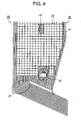
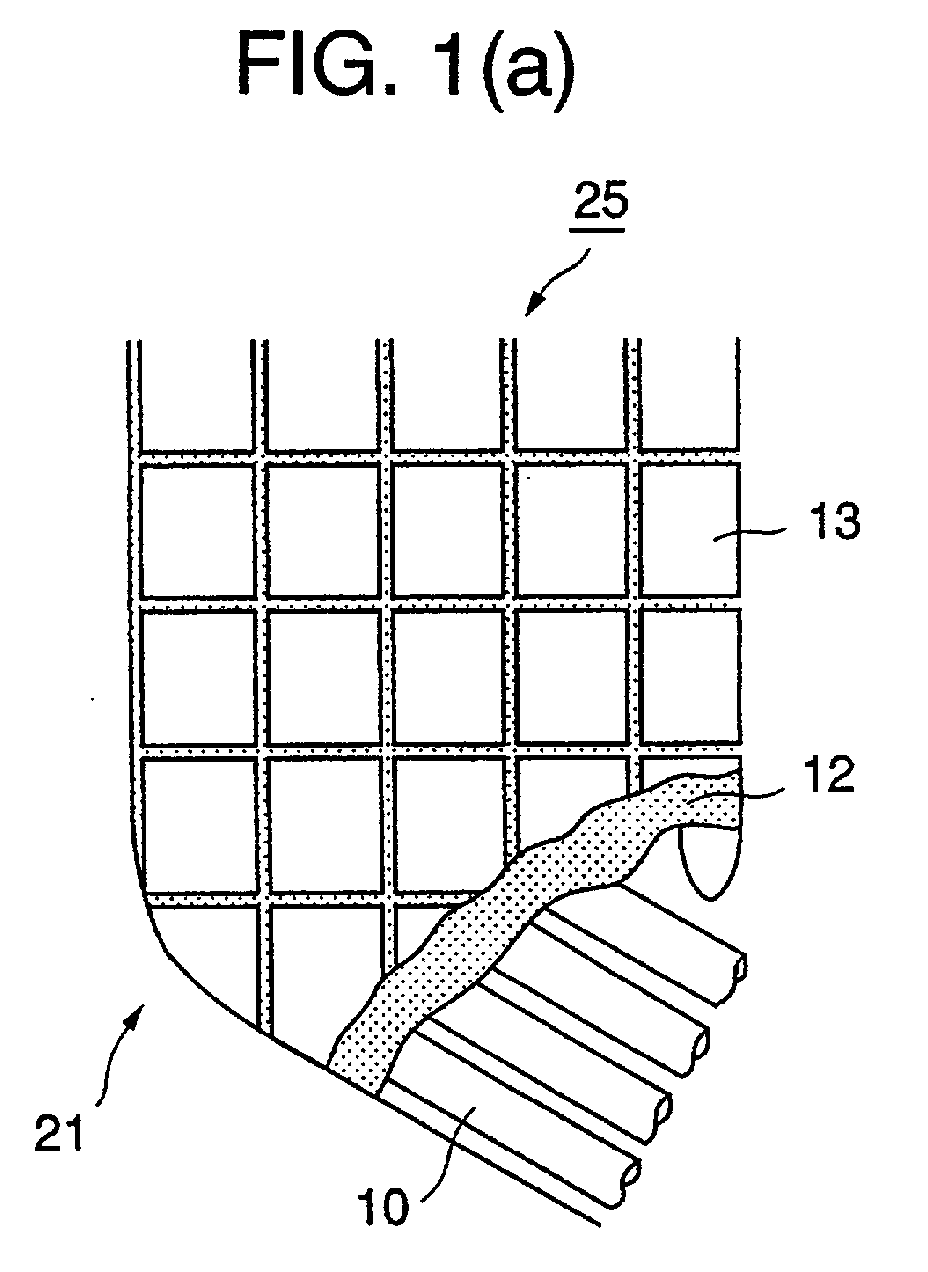
- Figure 1 (a) shows a cut-away perspective view of a first embodiment of this invention's fireproof structure for protecting water pipes, which is installed in an area where the pipes bend
- Figure 1 (b) is a diagram of the bend area in the water pipe wall.
- Figure 2 (a) is a sectional view of a second embodiment of this invention showing fireproof structure for protecting water pipes at the thermometer seat, and Figure 2 (b), a diagram of the thermometer opening.
- Figure 3 (a) is a sectional view of a third embodiment of this invention's fireproof structure for protecting water pipes around the manhole area
- Figure 3 (b) is a diagram of the manhole.
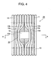
- Figure 4 is a diagram of the structure of the water pipe protective structure around the manhole of a stoker type incinerator.
- Figure 5 is a cross sectional drawing of a double-layered structure according to another preferred embodiment.
- Figure 6 is a cross sectional drawing of double-layered structure according to another preferred embodiment.
- Figure 7 is a cross sectional drawing of double-layered structure according to another preferred embodiment.
- Figure 8 is a diagram of a water pipe wall of stoker type incinerator.
- Figure 9 is an overall sketch of a stoker type incinerator.
- Figure 1 (a) shows a cut-away perspective view of a first embodiment of this invention's fireproof structure for protecting water pipes, which is installed in an area where the pipes bend
- Figure 1 (b) is a diagram of the bend area in the water pipe wall
- Figure 2 (a) is a sectional view of a second embodiment of this invention's fireproof structure for protecting water pipes at the thermometer seat
- Figure 2 (b) a diagram of the thermometer opening
- Figure 3 (a) is a sectional view of a third embodiment of this invention's fireproof structure for protecting water pipes around the manhole area
- Figure 3 (b) is a diagram of the manhole
- Figure 4 is a diagram of the structure of the water pipe protective structure around the manhole of a stoker type incinerator.
- the water pipe walls to which the fireproof structure is installed are in a stoker type incinerator.
- stoker type incinerators are high temperature furnaces having outlet temperatures of about 900°C to 1200°C.
- FIGs 1 through 4 show the areas of the water pipes where bends occur, as shown in Figure 8, which was previously introduced to describe the prior art.
- Figure 1 shows bend area 21 located in the bottom of the incinerator
- Figure 2 the area where an opening exists, such as an opening for thermometer installation
- Figures 3 and 4 show the area of manhole 22, which is used for worker egress.
- 10 represents the water pipe forming the flow path for the coolant; fins 11 (see Figure 5) connect adjacent water pipes 10 either in the horizontal or vertical direction to compose a water pipe wall.
- 12 represents the refractory castable, which is an amorphous fireproof material primarily composed of SiC.
- 13 represents refractory tiles which are similarly comprised of SiC; said refractory castable 12 and refractory tiles 13 make up fireproof structure 25.
- the foregoing bend area 21 runs from the wall of the free board area to the grate area of the furnace wall, and since it is located in a high temperature area of about 800°C in this high temperature stoker type incinerator, it is necessary to install water pipes 10, as shown in Figure 1(b) and further, to protect said water pipes 10 by covering them with a fireproof structure such as shown in Figure 1(a).
- the entire surface is covered by the foregoing refractory tiles 13, which are held in place by an adhesive such as mortar.
- the refractory castable 12 and the refractory tiles 13 are held by retainers or fastening members to prevent from easily falling off.
- the installation method for the foregoing refractory castable 12 it may either be sprayed around the outside circumferential surfaces of the foregoing water pipes 10 and allowed to harden, or a mold may be placed opposite water pipes 10, the space filled with the castable, and removing the mold the castable cures.
- the foregoing refractory tiles 13 are preferably manufactured in a factory by molding, pressing, and firing materials primarily comprised of SiC, and said preformed refractory tiles 13 are then installed on the foregoing pipe wall 26.
- the foregoing refractory castable 12 rendered a flat installation surface for refractory tile 13
- the fireproof structure not only is it possible to reduce manufacturing costs, but it is also possible to more easily install the fireproof structure.
- FIG 2 shows a second embodiment of this invention's fireproof structure installed around a thermometer seat 24, which includes thermometer opening 17.
- said thermometer seat 24 is adjacent to two parallel water pipes 10a on either side which bend to form an open area where the thermometer opening 17 is located.
- Figure 2(a) is a sectional view taken along line A - A of Figure 2 (b). At the center of the gap between water pipe walls 26 lies the foregoing thermometer installation opening 17, and there are bends in water pipes 10a on either side to accommodate it.
- the water pipes 10a, around the thermometer seat 24 form an irregular pipe wall array.
- Refractory castable 12 is installed on the high temperature gas side, in other words, the side facing the inside of the furnace, of the foregoing water pipe wall 26 at least to the extent where the grooves formed between the water pipe wall are completely filled in to create a flat surface.
- flat refractory tiles 13 are installed with an adhesive such as mortar over the surface of refractory castable 12.
- the foregoing water pipes 10 have L-shaped hooks 15, which protrude toward the inside of the furnace.
- the foregoing refractory tiles 13 are structured to engage thereupon.
- adjacent water pipes 10, are linked by fins 11, which have protruding Y-shaped anchors 14 that serve as retainers to hold the foregoing refractory castable 12 in place.
- the studding the fastening members that engage the refractory tiles with the foregoing water pipes 10 improves the cooling effect for said fastening members, prevents the fastening members becoming damaged by the high temperatures, and increases their longevity. This makes it possible to prevent the foregoing refractory tiles 13 from falling off.
- the fastening members and retainers for the foregoing refractory tiles 13 and refractory castable 12 are best made from materials having thermal expansion rates that differ little from that of water pipes 10. Their shapes need not be confined to the above described L-shaped hooks 15 or Y-shaped retainers 14 so long as they serve the same purpose.
- Figure 3 a sectional view taken along line B-B of Figure 4; it shows a third embodiment of a fireproof structure according to this invention.
- Figure 4 shows a fireproof structure installed around manhole 22, which allows workers to enter and exit for maintenance and the like.
- This manhole area 22 has a total of 6 water pipes 10, 3 on each side, which bend to form a manhole 18.
- the two in the center 10b, 10b are bent and overlay adjacent water pipes 10c, 10d, and further, water pipes 10c and 10c are bent toward the outside of the incinerator to avoid interference with the foregoing pipes 10b.
- water pipes 10 have complex bends that form a three dimensional structure.
- first refractory castable 12 is used to fill the gaps between water pipes 10, 10b, 10c, and 10d to create a flat surface that faces the inside of the incinerator, and then, flat refractory tiles 13 are installed with mortar.
- the structure includes L-shaped hooks 15, studded around water pipes 10 and protruding toward the inside of the incinerator, which engage the L-shaped groove formed in the foregoing refractory tiles 13 to hold the tiles in place.
- This type of structure makes it possible to install a fireproof structure that completely protects water pipe walls having a complex shape by using just one or a few types of refractory tiles.
- Figures 5 through 7 show sectional views of fastening and support structures for the foregoing refractory tiles and refractory castables.
- Figure 5 shows a fireproof structure that employs L-shaped hooks 15 and Y-shaped anchors similar to those of Figure 2.
- the foregoing water pipes 10 have one protruding L-shaped hook 15 for each refractory tile 13, but other structures, having more or fewer hooks, may be used depending upon the weight and surface area of the tiles.
- the foregoing refractory tiles, in addition to being retained by the foregoing hooks 15, are also held to the water pipe wall with mortar 19 adhesive.
- holes 11a are formed in fins 11 that join the foregoing water pipes 10 to each other. Then, following the installation of the foregoing refractory castable 12 and refractory tiles 13, water may be drained through holes 11a, and subsequently plugged by welding, etc. This makes it possible to easily drain the water from the surface of the foregoing refractory castable 12, even after refractory tiles 13 have been installed. It is also possible to form the foregoing holes 11a on the refractory tile 13 side, and then plug them with mortar after draining the water.
- Figure 6 shows a fireproof structure that employs a combination anchor and hook 16 which retains both the foregoing refractory castable 12 and refractory tiles 13 in place. So doing eliminates the need to separately manufacture anchors and hooks, and it eases the installation process.
- Figure 7 shows a fireproof structure that employs the foregoing L-shaped hooks 15 and the foregoing combination anchors and hooks 16. These can be used selectively, depending upon the layout of the foregoing water pipes 10 to retain the fireproof structures, and thereby ease the installation on water pipe walls having a complex shape.
- this invention by employing refractory castable to fill at least the concave areas in the water pipe wall to create a flat surface for the overlay of the refractory tiles, makes it possible to use flat refractory tiles, to thereby obviate the need to manufacture multiple types of the refractory tiles to conform to the areas where the water pipes assume a complex shape, and to facilitate their installation. Further, since it is possible to install the fireproof structure over the complete surface of the water pipe wall using one or only a few types of refractory tiles, it is less costly to manufacture said refractory tiles and easier to install the fireproof structure.
- the fireproof structure is a double-layered structure comprised of refractory castable and refractory tiles, even in the event that any of the foregoing refractory tiles fall off inside the high temperature gas environment, the underlying water pipes will remain protected by the foregoing refractory castable, which assures that said water pipes will not become exposed.
Landscapes
- Engineering & Computer Science (AREA)
- Chemical & Material Sciences (AREA)
- Combustion & Propulsion (AREA)
- Mechanical Engineering (AREA)
- General Engineering & Computer Science (AREA)
- Furnace Housings, Linings, Walls, And Ceilings (AREA)
- Sink And Installation For Waste Water (AREA)
- Rigid Pipes And Flexible Pipes (AREA)
Abstract
Description
Claims (9)
- An installation method for a fireproof structure to protect water pipes, which protects water pipe walls installed in the bend areas in incinerators, boilers and the like from the high temperature environment, comprising:a refractory castable process to embed refractory castable in concave area between adjacent water pipes, at least in the areas where the pipes bend to create an approximately flat surface on the water pipe wall that faces the high temperature side; anda refractory tile process to install approximately flat-shaped refractory tiles over the surface of said embedded refractory castable.
- An installation method for a fireproof structure according to claim 1, wherein said process to install the flat-shaped refractory tiles includes:a process to insert fastening members previously installed on the foregoing water pipe wall into a groove formed in said refractory tiles to hold said tiles in place; anda process to bind said refractory tiles to said embedded refractory castable by an adhesive material.
- An installation method for a fireproof structure according to claim 1, wherein said refractory castable is installed in a manner such that the ratio between the radius of the foregoing water pipes and the thickness of said refractory castable falls within the range of approximately 1 : 1 to 1.5.
- An installation method for a fireproof structure according to claim 1, wherein said fireproof structure is installed upon water pipe walls in stoker type incinerators where the gas retention time is 2 seconds or more from the secondary air duct, and the incinerator outlet temperature to an upper limit of the fireproof installation reaches about 900°C to 1200°C.
- An installation method for a fireproof structure according to claim 1, wherein said refractory castable process further includes, prior to the installation process for said refractory castable, a drain process to form water drain-holes in the fins that join adjacent runs of the water pipes, and drain the water from said water drain-holes after said refractory tile process.
- A fireproof structure to protect water pipes, which protects water pipe walls installed in the bend areas in incinerators, boilers and the like from the high temperature environment, comprising:a refractory castable embedded in the concave area between adjacent water pipes, at least in the areas where the pipes bend, to create an approximately flat surface; anda flat refractory tile installed over the surface of said refractory castable.
- A fireproof structure to protect water pipes according to claim 6, wherein said refractory tile is held in place by engaging the fasting member previously installed on the foregoing water pipe wall with a groove formed in said refractory tile, and binding said refractory tile to said refractory castable with an adhesive.
- A fireproof structure to protect water pipes according to claim 6, wherein the ratio between the radius of the foregoing water pipes and the thickness of said refractory castable falls within the range of approximately 1 : 1 to 1.5.
- A fireproof structure to protect water pipes according to claim 6, wherein said fireproof structure is installed upon water pipe walls in stoker type incinerators where the gas retention time is 2 seconds or more from the secondary air duct, and the incinerator outlet temperature to an upper limit of the fireproof installation reaches about 900°C to 1200°C.
Applications Claiming Priority (2)
| Application Number | Priority Date | Filing Date | Title |
|---|---|---|---|
| JP2001348544 | 2001-11-14 | ||
| JP2001348544A JP3842997B2 (en) | 2001-11-14 | 2001-11-14 | Refractory structure for water pipe protection and its construction method |
Publications (3)
| Publication Number | Publication Date |
|---|---|
| EP1312882A2 true EP1312882A2 (en) | 2003-05-21 |
| EP1312882A3 EP1312882A3 (en) | 2004-04-07 |
| EP1312882B1 EP1312882B1 (en) | 2007-07-25 |
Family
ID=19161351
Family Applications (1)
| Application Number | Title | Priority Date | Filing Date |
|---|---|---|---|
| EP02025279A Expired - Lifetime EP1312882B1 (en) | 2001-11-14 | 2002-11-12 | Installation method of fireproof structure for protecting water pipes |
Country Status (7)
| Country | Link |
|---|---|
| US (1) | US6837015B2 (en) |
| EP (1) | EP1312882B1 (en) |
| JP (1) | JP3842997B2 (en) |
| AT (1) | ATE368205T1 (en) |
| DE (1) | DE60221336T2 (en) |
| SG (1) | SG109999A1 (en) |
| TW (1) | TWI297068B (en) |
Cited By (2)
| Publication number | Priority date | Publication date | Assignee | Title |
|---|---|---|---|---|
| WO2006072425A1 (en) * | 2004-12-30 | 2006-07-13 | Saint-Gobain Industriekeramik Düsseldorf Gmbh | Refractory body for the protection system of a furnace internal wall |
| EP2138791A1 (en) * | 2008-06-26 | 2009-12-30 | Aga AB | Lining element for an industrial furnace |
Families Citing this family (11)
| Publication number | Priority date | Publication date | Assignee | Title |
|---|---|---|---|---|
| KR200467138Y1 (en) * | 2011-03-14 | 2013-05-29 | 정해경 | Fire-proof wall structure for incinerator |
| JP6081811B2 (en) * | 2013-02-15 | 2017-02-15 | 三菱日立パワーシステムズ株式会社 | Recovery method of boiler penetration structure and boiler penetration structure |
| JP6458410B2 (en) * | 2014-09-01 | 2019-01-30 | 住友金属鉱山株式会社 | Waste heat boiler for non-ferrous metal smelting furnace |
| JP7049080B2 (en) * | 2017-08-16 | 2022-04-06 | 三菱重工業株式会社 | Suit blower device and boiler |
| JP2019191065A (en) * | 2018-04-27 | 2019-10-31 | 三菱日立パワーシステムズ株式会社 | Flaw inspection method of pipe member and flaw inspection system of the same |
| CN108907064A (en) * | 2018-09-17 | 2018-11-30 | 浙江杭摩欧亿汽车零部件有限公司 | The pressed radiator of brake block |
| JP2021042535A (en) * | 2019-09-06 | 2021-03-18 | 三菱パワー株式会社 | Working scaffold installation structure in boiler furnace |
| CN113819343B (en) * | 2021-09-30 | 2022-11-08 | 上海宝冶集团有限公司 | Method for fixing super heat-insulating material of water beam column of heating furnace |
| FI131442B1 (en) * | 2023-02-28 | 2025-04-23 | Valmet Technologies Oy | Wall for a fluidized bed boiler and a fluidized bed boiler |
| KR102860240B1 (en) * | 2025-01-03 | 2025-09-16 | (주)건일 | Refractory Block Unit for Installing Water Tubes in an Incinerator |
| CN121067626B (en) * | 2025-11-06 | 2026-02-17 | 湖南蓝伯化工有限责任公司 | A suspension device for a calcium carbide furnace screen |
Family Cites Families (14)
| Publication number | Priority date | Publication date | Assignee | Title |
|---|---|---|---|---|
| US2703559A (en) * | 1949-11-19 | 1955-03-08 | Babcock & Wilcox Co | Wall construction for fluid heat exchange installation |
| DE3036564A1 (en) * | 1980-09-27 | 1982-04-22 | Mannesmann AG, 4000 Düsseldorf | VESSEL FOR A METAL MELTING STOVE |
| FR2495284B1 (en) * | 1980-11-28 | 1985-12-06 | Mediterranee Const Navales Ind | METHOD OF PROTECTING TUBULAR BEAM SCREENS OF BOILER COMBUSTION CHAMBERS, IN PARTICULAR OF HOUSEHOLD INCINERATION |
| CA1257473A (en) * | 1984-10-12 | 1989-07-18 | Willard Mcclintock | Furnace cooling system and method |
| US4746337A (en) * | 1987-07-06 | 1988-05-24 | Foster Wheeler Energy Corporation | Cyclone separator having water-steam cooled walls |
| DE4103508A1 (en) * | 1991-02-06 | 1992-08-13 | Kortec Ag | METHOD AND DEVICE FOR COOLING VESSEL PARTS FOR CARRYING OUT PYRO METHODS, IN PARTICULAR METALLURGICAL TYPE |
| LU88399A1 (en) * | 1993-09-01 | 1995-04-05 | Wurth Paul Sa | Distribution chute for installation in an oven |
| DE4335707C2 (en) * | 1993-10-20 | 1995-08-10 | Didier Werke Ag | Cladding of a combustion chamber wall |
| US5423294A (en) * | 1993-12-03 | 1995-06-13 | Wheelabrator Environmental Systems, Inc. | Furnace tile and expansion joint |
| US5557901A (en) * | 1994-11-15 | 1996-09-24 | The Babcock & Wilcox Company | Boiler buckstay system |
| EP0962696A4 (en) * | 1997-11-28 | 2002-03-06 | Mitsubishi Heavy Ind Ltd | Water tube protective refractory structure and method of assembling the same |
| DE19825546C1 (en) * | 1998-06-08 | 1999-08-26 | Didier Werke Ag | Device for fixing cladding plates of fireproof ceramic material to metal wall |
| DE10005426C2 (en) | 2000-02-08 | 2001-11-15 | Didier Werke Ag | Refractory ceramic plate and associated wall structure for an incinerator |
| TWI226418B (en) * | 2001-11-08 | 2005-01-11 | Mitsubishi Heavy Ind Ltd | Fireproof structure and installation method for protecting water pipes |
-
2001
- 2001-11-14 JP JP2001348544A patent/JP3842997B2/en not_active Expired - Lifetime
-
2002
- 2002-11-12 DE DE60221336T patent/DE60221336T2/en not_active Expired - Fee Related
- 2002-11-12 AT AT02025279T patent/ATE368205T1/en not_active IP Right Cessation
- 2002-11-12 EP EP02025279A patent/EP1312882B1/en not_active Expired - Lifetime
- 2002-11-13 SG SG200206806A patent/SG109999A1/en unknown
- 2002-11-14 TW TW091133384A patent/TWI297068B/en not_active IP Right Cessation
- 2002-11-14 US US10/293,499 patent/US6837015B2/en not_active Expired - Fee Related
Cited By (2)
| Publication number | Priority date | Publication date | Assignee | Title |
|---|---|---|---|---|
| WO2006072425A1 (en) * | 2004-12-30 | 2006-07-13 | Saint-Gobain Industriekeramik Düsseldorf Gmbh | Refractory body for the protection system of a furnace internal wall |
| EP2138791A1 (en) * | 2008-06-26 | 2009-12-30 | Aga AB | Lining element for an industrial furnace |
Also Published As
| Publication number | Publication date |
|---|---|
| TWI297068B (en) | 2008-05-21 |
| EP1312882A3 (en) | 2004-04-07 |
| US20030089072A1 (en) | 2003-05-15 |
| JP2003148713A (en) | 2003-05-21 |
| US6837015B2 (en) | 2005-01-04 |
| EP1312882B1 (en) | 2007-07-25 |
| SG109999A1 (en) | 2005-04-28 |
| DE60221336D1 (en) | 2007-09-06 |
| JP3842997B2 (en) | 2006-11-08 |
| TW200304532A (en) | 2003-10-01 |
| ATE368205T1 (en) | 2007-08-15 |
| DE60221336T2 (en) | 2008-05-08 |
Similar Documents
| Publication | Publication Date | Title |
|---|---|---|
| US6837015B2 (en) | Installation method of fireproof structure for protecting water pipes | |
| EP0116233B1 (en) | Fire stop | |
| US7204061B2 (en) | Fireproof structure and installation method for protecting water pipes | |
| US5542378A (en) | Waterwall tube block design | |
| JP4988356B2 (en) | Thermal protector and protection system | |
| US5154139A (en) | Refractory tube block | |
| EP1443269A1 (en) | Fixing structure of refractory tile for protecting water tube and refractory structure for protecting water tube | |
| FI87489B (en) | LUFTKYLD ELDSTADSVAEGG. | |
| KR101246593B1 (en) | Refractory tile, in particular for gasifier | |
| PL196273B1 (en) | Refractory ceramic panel for lining furnace walls and incinerating furnace wall lining | |
| JP2003262323A (en) | Water-cooled wall structure for stoker type incinerator | |
| WO2007137189A2 (en) | Refractory tiles for heat exchangers | |
| US20060101740A1 (en) | Refractory tiles and mounting methods | |
| JP2004520561A5 (en) | ||
| JP2003207101A (en) | Water pipe protecting refractory structure and its constructing method | |
| RU2337274C2 (en) | Heating device | |
| RU2099641C1 (en) | Fireplace | |
| JP2003254502A (en) | Water-cooled wall structure of boiler | |
| US20120266826A1 (en) | System, method and apparatus for thermally conductive refractory tiles for waste to energy boiler walls | |
| CA1288003C (en) | Method of building refractory protection walls of ovens, furnaces andcombustion chambers, and fire- brick therefor | |
| JP2960318B2 (en) | Thin-walled fixed refractory structure for water pipe wall protection | |
| HRP990034A2 (en) | Coated stone for multipipe chimney | |
| JP2006342292A (en) | Insulation box used for hot repair of coke oven carbonization chamber | |
| KR19980043774A (en) | Air-cooled Incinerator with Ceramic Tile |
Legal Events
| Date | Code | Title | Description |
|---|---|---|---|
| PUAI | Public reference made under article 153(3) epc to a published international application that has entered the european phase |
Free format text: ORIGINAL CODE: 0009012 |
|
| 17P | Request for examination filed |
Effective date: 20021112 |
|
| AK | Designated contracting states |
Designated state(s): AT BE BG CH CY CZ DE DK EE ES FI FR GB GR IE IT LI LU MC NL PT SE SK TR |
|
| AX | Request for extension of the european patent |
Extension state: AL LT LV MK RO SI |
|
| PUAL | Search report despatched |
Free format text: ORIGINAL CODE: 0009013 |
|
| AK | Designated contracting states |
Kind code of ref document: A3 Designated state(s): AT BE BG CH CY CZ DE DK EE ES FI FR GB GR IE IT LI LU MC NL PT SE SK TR |
|
| AX | Request for extension of the european patent |
Extension state: AL LT LV MK RO SI |
|
| RIC1 | Information provided on ipc code assigned before grant |
Ipc: 7F 23M 5/04 B Ipc: 7F 27D 1/00 A Ipc: 7F 23M 5/08 B Ipc: 7F 27D 1/12 B |
|
| AKX | Designation fees paid |
Designated state(s): AT CH DE FR GB IT LI |
|
| GRAP | Despatch of communication of intention to grant a patent |
Free format text: ORIGINAL CODE: EPIDOSNIGR1 |
|
| GRAS | Grant fee paid |
Free format text: ORIGINAL CODE: EPIDOSNIGR3 |
|
| GRAA | (expected) grant |
Free format text: ORIGINAL CODE: 0009210 |
|
| AK | Designated contracting states |
Kind code of ref document: B1 Designated state(s): AT CH DE FR GB IT LI |
|
| REG | Reference to a national code |
Ref country code: GB Ref legal event code: FG4D |
|
| RIN1 | Information on inventor provided before grant (corrected) |
Inventor name: NAKAGAWA, YUJI,M Inventor name: SAEKI, KENTARO,M Inventor name: INOUE, KEITA,M Inventor name: TERABE, YASUNORI,M |
|
| REG | Reference to a national code |
Ref country code: CH Ref legal event code: EP |
|
| REG | Reference to a national code |
Ref country code: CH Ref legal event code: NV Representative=s name: E. BLUM & CO. AG PATENT- UND MARKENANWAELTE VSP |
|
| REF | Corresponds to: |
Ref document number: 60221336 Country of ref document: DE Date of ref document: 20070906 Kind code of ref document: P |
|
| ET | Fr: translation filed | ||
| PLBE | No opposition filed within time limit |
Free format text: ORIGINAL CODE: 0009261 |
|
| STAA | Information on the status of an ep patent application or granted ep patent |
Free format text: STATUS: NO OPPOSITION FILED WITHIN TIME LIMIT |
|
| 26N | No opposition filed |
Effective date: 20080428 |
|
| PGFP | Annual fee paid to national office [announced via postgrant information from national office to epo] |
Ref country code: CH Payment date: 20081117 Year of fee payment: 7 Ref country code: DE Payment date: 20081107 Year of fee payment: 7 |
|
| PGFP | Annual fee paid to national office [announced via postgrant information from national office to epo] |
Ref country code: AT Payment date: 20081112 Year of fee payment: 7 |
|
| PGFP | Annual fee paid to national office [announced via postgrant information from national office to epo] |
Ref country code: IT Payment date: 20081125 Year of fee payment: 7 |
|
| PGFP | Annual fee paid to national office [announced via postgrant information from national office to epo] |
Ref country code: FR Payment date: 20081112 Year of fee payment: 7 |
|
| PGFP | Annual fee paid to national office [announced via postgrant information from national office to epo] |
Ref country code: GB Payment date: 20081112 Year of fee payment: 7 |
|
| REG | Reference to a national code |
Ref country code: CH Ref legal event code: PL |
|
| GBPC | Gb: european patent ceased through non-payment of renewal fee |
Effective date: 20091112 |
|
| REG | Reference to a national code |
Ref country code: FR Ref legal event code: ST Effective date: 20100730 |
|
| PG25 | Lapsed in a contracting state [announced via postgrant information from national office to epo] |
Ref country code: AT Free format text: LAPSE BECAUSE OF NON-PAYMENT OF DUE FEES Effective date: 20091112 |
|
| PG25 | Lapsed in a contracting state [announced via postgrant information from national office to epo] |
Ref country code: LI Free format text: LAPSE BECAUSE OF NON-PAYMENT OF DUE FEES Effective date: 20091130 Ref country code: FR Free format text: LAPSE BECAUSE OF NON-PAYMENT OF DUE FEES Effective date: 20091130 Ref country code: CH Free format text: LAPSE BECAUSE OF NON-PAYMENT OF DUE FEES Effective date: 20091130 |
|
| PG25 | Lapsed in a contracting state [announced via postgrant information from national office to epo] |
Ref country code: DE Free format text: LAPSE BECAUSE OF NON-PAYMENT OF DUE FEES Effective date: 20100601 |
|
| PG25 | Lapsed in a contracting state [announced via postgrant information from national office to epo] |
Ref country code: GB Free format text: LAPSE BECAUSE OF NON-PAYMENT OF DUE FEES Effective date: 20091112 |
|
| PG25 | Lapsed in a contracting state [announced via postgrant information from national office to epo] |
Ref country code: IT Free format text: LAPSE BECAUSE OF NON-PAYMENT OF DUE FEES Effective date: 20091112 |