EP1312808B1 - Rotor blade for centrifugal compressor - Google Patents
Rotor blade for centrifugal compressor Download PDFInfo
- Publication number
- EP1312808B1 EP1312808B1 EP02257867A EP02257867A EP1312808B1 EP 1312808 B1 EP1312808 B1 EP 1312808B1 EP 02257867 A EP02257867 A EP 02257867A EP 02257867 A EP02257867 A EP 02257867A EP 1312808 B1 EP1312808 B1 EP 1312808B1
- Authority
- EP
- European Patent Office
- Prior art keywords
- rotor
- axis
- blade
- centrifugal compressor
- coordinates
- Prior art date
- Legal status (The legal status is an assumption and is not a legal conclusion. Google has not performed a legal analysis and makes no representation as to the accuracy of the status listed.)
- Expired - Lifetime
Links
- 238000009826 distribution Methods 0.000 description 2
- 238000000034 method Methods 0.000 description 2
- 238000004458 analytical method Methods 0.000 description 1
- 238000004364 calculation method Methods 0.000 description 1
- 230000001419 dependent effect Effects 0.000 description 1
- 239000012530 fluid Substances 0.000 description 1
- 238000003754 machining Methods 0.000 description 1
- 238000004519 manufacturing process Methods 0.000 description 1
- 230000002093 peripheral effect Effects 0.000 description 1
Images

Classifications
-
- F—MECHANICAL ENGINEERING; LIGHTING; HEATING; WEAPONS; BLASTING
- F04—POSITIVE - DISPLACEMENT MACHINES FOR LIQUIDS; PUMPS FOR LIQUIDS OR ELASTIC FLUIDS
- F04D—NON-POSITIVE-DISPLACEMENT PUMPS
- F04D29/00—Details, component parts, or accessories
- F04D29/26—Rotors specially for elastic fluids
- F04D29/28—Rotors specially for elastic fluids for centrifugal or helico-centrifugal pumps for radial-flow or helico-centrifugal pumps
- F04D29/30—Vanes
Definitions
- the present invention relates to a rotor blade for a centrifugal compressor with a medium flow coefficient.
- the invention relates to a cylindrical blade for a centrifugal rotor of a multi-stage compressor.
- This dimensionless coefficient can be used to define the operating characteristic of the compressor, and can be used to classify the different types of compressor at the design stage.
- Compressors are therefore made to handle different flow rates, in other words to operate with different values of the flow coefficient, according to the applications for which they are intended.
- compressors with a medium flow coefficient in which ⁇ has values in the vicinity of 0.04, and compressors with a medium-high flow coefficient, for which ⁇ is approximately 0.06.
- the geometric configuration of the rotor blading significantly affects the aerodynamic efficiency (see for example GB 1144445 which propose a calculation foor the vane angles in order to increase the aerodynamic efficiency), due to the fact that the geometric characteristics of the blade determine the distribution of the relative velocities of the fluid along the rotor, thus affecting the distribution of the boundary layers along the walls and, in the final analysis, the friction losses.
- the aerodynamic efficiency is particularly critical for rotors made with stages having two-dimensional blades, in other words purely radial rotors in which the blades are flat or cylindrical with generatrices parallel to the axis of rotation of the rotor.
- the blades used in this type of rotor have a relatively simple geometry in which the median line of the section consists of an arc of a circumference and the thickness is constant along the blade, except in the region of the leading edge, which is formed by a semicircular fillet or, in particular cases, by a tapering of the thickness.
- the present invention therefore seeks to provide a blade which, by means of a suitable configuration, enables a high aerodynamic efficiency to be achieved.
- the present invention also seeks to provide a blade which can be manufactured economically on a large scale by automated processes.
- a cylindrical blade for a rotor of the purely radial type of a centrifugal compressor with a medium flow coefficient comprising a first surface of the pressure side and a second surface of the suction side having equal curvature, both having generatrices parallel to the axis (Z) of rotation of the rotor, characterized in that the intersection of each of the said surfaces on a plane (Y, X) of a right-hand Cartesian reference system (Y, X, Z), having an axis of ordinates (X) and an axis of abscissae (Y), and an axis (Z) coinciding with the axis of rotation of the rotor, is a curved line defined by a discrete set of points belonging to the said curve whose coordinates (y) on the axis of abscissae and (x) on the axis of ordinates are expressed as a function of the outer radius (R) of the rot
- a rotor 10 of the purely radial type with an outer radius R belonging to a centrifugal compressor with a medium flow coefficient comprises a plurality of cylindrical blades 1.
- Each blade 1 comprises a first surface 3 of the pressure side facing forwards with respect to the direction of rotation of the rotor, indicated by the arrow F, and a second surface 5 of the suction side, opposite the first surface.
- the surfaces 3 and 5 are substantially cylindrical, have equal curvature, and are made with generatrices parallel to the axis Z of rotation of the rotor 10.
- the two surfaces 3 and 5 are joined together at one end by a known method; for example, a tapering of the thicknesses, or alternatively a semicircular fillet (not illustrated) is provided at the leading edge 4.
- each of the said surfaces 3 and 5 on a plane Y, X of a right-handed Cartesian system Y, X, Z, having an axis of ordinates X, an axis of abscissae Y, and an axis Z coinciding with the axis of rotation of the rotor 10, is a curved line 7 defined by a discrete set of points 9 belonging to the said curve 7, whose coordinates y, on the axis of abscissae, and x, on the axis of ordinates, are conveniently expressed as a function of the outer radius R of the rotor.
- the surfaces 3 and 5, and substantially the blade 1 can be conveniently formed by means of automatic machines, for example those of the numerically controlled type, or the like.
- the rotor 10 and correspondingly the blades 1 can also be made in various sizes.
- the characteristics of a rotor are in fact, within certain limits, substantially dependent on the curvature of the blades, and are therefore, as a first approximation, equal for similar rotors.
- the curve 7 of the blade 1 according to the invention expressed as a function of the outer radius R of the rotor, in the form, respectively, of the ratios y/R and x/R between the values of the coordinates of each point and the value of the said radius R, is defined by the following values:
- a rotor 10 was made with an outer radius of 200 mm and with 17 cylindrical blades 1 having surfaces 3 of the pressure sides and surfaces 5 of the suction sides with equal curvature, defined by the following coordinates y, x of a discrete set of points 9 of the curve 7 of the intersection of one of the surfaces 3 and 5 with the plane Y, X of a right-hand system of Cartesian axes Y, X, Z where Y is the axis of abscissae and X is the axis of ordinates:
Landscapes
- Engineering & Computer Science (AREA)
- Mechanical Engineering (AREA)
- General Engineering & Computer Science (AREA)
- Structures Of Non-Positive Displacement Pumps (AREA)
Description
- The present invention relates to a rotor blade for a centrifugal compressor with a medium flow coefficient.
- More precisely, the invention relates to a cylindrical blade for a centrifugal rotor of a multi-stage compressor.
- In the field of centrifugal compressors, the flow coefficient is defined as Φ = (4*q)/(π*d2*u") in which:
- q is the volume flow rate;
- d is the outer diameter of the rotor;
- u" is the peripheral velocity of the rotor.
- This dimensionless coefficient can be used to define the operating characteristic of the compressor, and can be used to classify the different types of compressor at the design stage.
- Compressors are therefore made to handle different flow rates, in other words to operate with different values of the flow coefficient, according to the applications for which they are intended.
- For example, we may mention compressors with a medium flow coefficient, in which Φ has values in the vicinity of 0.04, and compressors with a medium-high flow coefficient, for which Φ is approximately 0.06.
- However, one of the main requirements common to all compressors relates to the high aerodynamic efficiency which must be attained in most of the stages.
- The geometric configuration of the rotor blading significantly affects the aerodynamic efficiency (see for example
GB 1144445 - The aerodynamic efficiency is particularly critical for rotors made with stages having two-dimensional blades, in other words purely radial rotors in which the blades are flat or cylindrical with generatrices parallel to the axis of rotation of the rotor.
- Conventionally, for reasons of economy in manufacture, the blades used in this type of rotor have a relatively simple geometry in which the median line of the section consists of an arc of a circumference and the thickness is constant along the blade, except in the region of the leading edge, which is formed by a semicircular fillet or, in particular cases, by a tapering of the thickness.
- Although two-dimensional blades are made by relatively simple machining processes and are therefore very widely used, their geometry does not enable a high aerodynamic efficiency of the rotor to be achieved.
- The present invention therefore seeks to provide a blade which, by means of a suitable configuration, enables a high aerodynamic efficiency to be achieved.
- The present invention also seeks to provide a blade which can be manufactured economically on a large scale by automated processes.
- According to the invention, there is provided a cylindrical blade for a rotor of the purely radial type of a centrifugal compressor with a medium flow coefficient, the said blade comprising a first surface of the pressure side and a second surface of the suction side having equal curvature, both having generatrices parallel to the axis (Z) of rotation of the rotor, characterized in that the intersection of each of the said surfaces on a plane (Y, X) of a right-hand Cartesian reference system (Y, X, Z), having an axis of ordinates (X) and an axis of abscissae (Y), and an axis (Z) coinciding with the axis of rotation of the rotor, is a curved line defined by a discrete set of points belonging to the said curve whose coordinates (y) on the axis of abscissae and (x) on the axis of ordinates are expressed as a function of the outer radius (R) of the rotor as the ratios y/R and x/R respectively between the values of the coordinate of each point and the value of the said radius (R) of the rotor, the coordinates (y, x) of the said points being variable within a range of ± 0.600 mm on both the abscissa and the ordinate:
- x/R = 0.450; y/R = -0.397
- x/R = 0.455; y/R = -0.391
- x/R = 0.461; y/R = -0.387
- x/R = 0.468; y/R = -0.384
- x/R = 0.474; y/R = -0.381
- x/R = 0.480; y/R = -0.377
- x/R = 0.486; y/R = -0.374
- x/R = 0.493; y/R = -0.371
- x/R = 0.499; y/R = -0.368
- x/R = 0.505; y/R = -0.365
- x/R = 0.512; y/R = -0.362
- x/R = 0.518; y/R = -0.359
- x/R = 0.524; y/R = -0.356
- x/R = 0.531; y/R = -0.353
- x/R = 0.537; y/R = -0.350
- x/R = 0.543; y/R = -0.347
- x/R = 0.550; y/R = -0.344
- x/R = 0.556; y/R = -0.341
- x/R = 0.562; y/R = -0.337
- x/R = 0.568; y/R = -0.334
- x/R = 0.575; y/R = -0.331
- x/R = 0.581; y/R = -0.328
- x/R = 0.587; y/R = -0.321
- x/R = 0.593; y/R = -0.321
- x/R = 0.599; y/R = -0.318
- x/R = 0.605; y/R = -0.314
- x/R = 0.612; y/R = -0.311
- x/R = 0.618; y/R = -0.307
- x/R = 0.624; y/R = -0.303
- x/R = 0.630; y/R = -0.300
- x/R = 0.650; y/R = -0.287
- x/R = 0.670; y/R = -0.275
- x/R = 0.690; y/R = -0.261
- x/R = 0.709; y/R = -0.248
- x/R = 0.729; y/R = -0.234
- x/R = 0.748; y/R = -0.220
- x/R = 0.767; y/R = -0.205
- x/R = 0.785; y/R = -0.190
- x/R = 0.804; y/R = -0.175
- x/R = 0.822; y/R = -0.160
- x/R = 0.844; y/R = -0.140
- x/R = 0.866; y/R = -0.120
- x/R = 0.888; y/R = -0.100
- x/R = 0.910; y/R = -0.079
- x/R = 0.931; y/R = -0.058
- x/R = 0.952; y/R = -0.037
- x/R = 0.972; y/R = -0.015
- x/R = 0.993; y/R = 0.007
- The invention will now be described in greater detail, by way of example, with reference to the drawings, in which:-
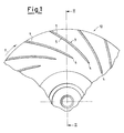
- Figure 1 is a front view, in partial section, of a rotor having blades according to the invention;
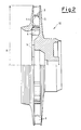
- Figure 2 is a view, in partial section, of the rotor, taken through the line II-II in Figure 1;
- Figure 3 is a schematic axonometric view of a blade according to the invention;
- Figure 4 shows the profile of the blade of Figure 3 at the position of its geometric intersection with the hub of the rotor.
- With reference to Figures 1 and 2, a
rotor 10 of the purely radial type with an outer radius R belonging to a centrifugal compressor with a medium flow coefficient comprises a plurality ofcylindrical blades 1. - Each
blade 1 comprises afirst surface 3 of the pressure side facing forwards with respect to the direction of rotation of the rotor, indicated by the arrow F, and asecond surface 5 of the suction side, opposite the first surface. - The
surfaces rotor 10. - The two
surfaces leading edge 4. - With reference to Figures 3 and 4, the projection of each of the said surfaces 3 and 5 on a plane Y, X of a right-handed Cartesian system Y, X, Z, having an axis of ordinates X, an axis of abscissae Y, and an axis Z coinciding with the axis of rotation of the
rotor 10, is acurved line 7 defined by a discrete set ofpoints 9 belonging to the saidcurve 7, whose coordinates y, on the axis of abscissae, and x, on the axis of ordinates, are conveniently expressed as a function of the outer radius R of the rotor. - As a result of this definition of the
curve 7, thesurfaces blade 1, can be conveniently formed by means of automatic machines, for example those of the numerically controlled type, or the like. - According to the operating conditions for which they are intended, the
rotor 10 and correspondingly theblades 1 can also be made in various sizes. - According to the known law of similarity, the characteristics of a rotor are in fact, within certain limits, substantially dependent on the curvature of the blades, and are therefore, as a first approximation, equal for similar rotors.
- By applying the law of similarity, it is possible to disregard the absolute dimensions of the blade and define its geometry, for example by means of the ratios x/R and y/R of the coordinates of the
points 9 to the value of the outer radius R of the rotor. - It has also been found that the efficiency varies only slightly with the variation of the curvatures of the
surfaces curve 7 when this is kept within a range of variation of the coordinates y, x of thepoints 9 equal to ± 0.600 mm. - The
curve 7 of theblade 1 according to the invention, expressed as a function of the outer radius R of the rotor, in the form, respectively, of the ratios y/R and x/R between the values of the coordinates of each point and the value of the said radius R, is defined by the following values: - x/R = 0.450; y/R = -0.397
- x/R = 0.455; y/R = -0.391
- x/R = 0.461; y/R = -0.387
- x/R = 0.468; y/R = -0.384
- x/R = 0.474; y/R = -0.381
- x/R = 0.480; y/R = -0.377
- sir = 0.486; y/R = -0.374
- x/R = 0.493; y/R = -0.371
- x/R = 0.499; y/R = -0.368
- x/R = 0.505; y/R = -0.365
- x/R = 0.512; y/R = -0.362
- x/R = 0.518; y/R = -0.359
- x/R = 0.524; y/R = -0.356
- x/R = 0.531; y/R = -0.353
- x/R = 0.537; y/R = -0.350
- x/R = 0.543; y/R = -0.347
- x/R = 0.550; y/R = -0.344
- x/R = 0.556; y/R = -0.341
- x/R = 0.562; y/R = -0.337
- x/R = 0.568; y/R = -0.334
- x/R = 0.575; y/R = -0.331
- x/R = 0.581; y/R = -0.328
- x/R = 0.587; y/R = -0.321
- x/R = 0.593; y/R = -0.321
- x/R = 0.599; y/R = -0.318
- x/R = 0.605; y/R = -0.314
- x/R = 0.612; y/R = -0.311
- x/R = 0.618; y/R = -0.307
- x/R = 0.624; y/R = -0.303
- x/R = 0.630; y/R = -0.300
- x/R = 0.650; y/R = -0.287
- x/R = 0.670; y/R = -0.275
- x/R = 0.690; y/R = -0.261
- x/R = 0.709; y/R = -0.248
- x/R = 0.729; y/R = -0.234
- x/R = 0.748; y/R = -0.220
- x/R = 0.767; y/R = -0.205
- x/R = 0.785; y/R = -0.190
- x/R = 0.804; y/R = -0.175
- x/R = 0.822; y/R = -0.160
- x/R = 0.844; y/R = -0.140
- x/R = 0.866; y/R = -0.120
- x/R = 0.888; y/R = -0.100
- x/R = 0.910; y/R = -0.079
- x/R = 0.931; y/R = -0.058
- x/R = 0.952; y/R = -0.037
- x/R = 0.972; y/R = -0.015
- x/R = 0.993; y/R = 0.007.
- A
rotor 10 was made with an outer radius of 200 mm and with 17cylindrical blades 1 havingsurfaces 3 of the pressure sides andsurfaces 5 of the suction sides with equal curvature, defined by the following coordinates y, x of a discrete set ofpoints 9 of thecurve 7 of the intersection of one of thesurfaces - x = 89.957; y = -79.420;
- x = 91.036; y = -78.247;
- x = 92.261; y = -77.492;
- x = 93.504; y = -76.790;
- x = 94.753; y = -76.115;
- x = 96:007; y = -75.462;
- x = 97.264; y = -74.820;
- x = 98.524; y = -74.190;
- x = 99.788; y = -73.573;
- x = 101.064; y = -72.962;
- x = 102.321; y = -72.354;
- x = 103.592; y = -71.758;
- x = 104.867; y = -71.171;
- x = 106.139; y = -70.576;
- x = 107.407; y = -69.973;
- x = 108.673; y = -69.363;
- x = 109.934; y = -68.745;
- x = 111.191; y = -68.119;
- x = 112.449; y = -67.483;
- x = 113.692; y = -66.840;
- x = 114.937; y = -66.188;
- x = 116.177; y = -65.529;
- x = 117.414; y = -64.261;
- x = 118.646; y = -64.185;
- x = 119.874; y = -63.502;
- x = 121.098; y = -62.811;
- x = 122.317; y = -62.112;
- x = 123.533; y = -61.406;
- x = 124.744; y = -60.693;
- x = 125.951; y = -59.972;
- x = 130.003; y = -57.480;
- x = 134.008; y = -54.910;
- x = 137.965; y = -52.265;
- x = 141.875; y = -49.548;
- x = 145.737; y = -46.763;
- x = 149.553; y = -43.913;
- x = 153.323; y = -41.000;
- x = 157.048; y = -38.028;
- x = 160.728; y = -35.000;
- x = 164.365; y = -31.918;
- x = 168.848; y = -27.992;
- x = 173.262; y = -23.989;
- x = 177.613; y = -19.912;
- x = 181.903; y = -15.768;
- x = 186.137; y = -11.563;
- x = 190.317; y = -7.303;
- x = 194.448; y = -2.994;
- x = 198.537; y = 1.364.
- When this rotor was subjected to fluid-dynamic testing, its polytropic stage efficiency was found to be considerably higher than that of prior art rotors.
Claims (4)
- Cylindrical blade for a rotor of the purely radial type of a centrifugal compressor with a medium flow coefficient, the said blade (1) comprising a first surface (3) of the pressure side and a second surface (5) of the suction side having equal curvature, both having generatrices parallel to the axis (Z) of rotation of the rotor, characterized in that the intersection of each of the said surfaces (3, 5) on a plane (Y, X) of a right-hand Cartesian reference system (Y, X, Z), having an axis of ordinates (X) and an axis of abscissae (Y), and an axis (Z) coinciding with the axis of rotation of the rotor, is a curved line (7) defined by a discrete set of points belonging to the said curve (7) whose coordinates (y) on the axis of abscissae and (x) on the axis of ordinates are expressed as a function of the outer radius (R) of the rotor as the ratios y/R and x/R respectively between the values of the coordinate of each point and the value of the said radius (R) of the rotor, the coordinates (y, x) of the said points being variable within a range of ± 0.600 mm on both the abscissa and the ordinate:x/R = 0.450; y/R = -0.397x/R = 0.455; y/R = -0.391x/R = 0.461; y/R = -0.387x/R = 0.468; y/R = -0.384x/R = 0.474; y/R = -0.381x/R = 0.480; y/R = -0.377x/R = 0.486; y/R = -0.374x/R = 0.493; y/R = -0.371x/R = 0.499; y/R = -0.368x/R = 0.505; y/R = -0.365x/R = 0.512; y/R = -0.362x/R = 0.518; y/R = -0.359x/R = 0.524; y/R = -0.356x/R = 0.531; y/R = -0.353x/R = 0.537; y/R = -0.350x/R = 0.543; y/R = -0.347x/R = 0.550; y/R = -0.344x/R = 0.556; y/R = -0.341x/R = 0.562; y/R = -0.337x/R = 0.568; y/R = -0.334x/R = 0.575; y/R = -0.331x/R = 0.575; y/R = -0.331x/R = 0.581; y/R = -0.328x/R = 0.587; y/R = -0.321x/R = 0.593; y/R = -0.321x/R = 0.599; y/R = -0.318x/R = 0.605; y/R = -0.314x/R = 0.612; y/R = -0.311x/R = 0.618; y/R = -0.307x/R = 0.624; y/R = -0.303x/R = 0.630; y/R = -0.300x/R = 0.650; y/R = -0.287x/R = 0.670; y/R = -0.275x/R = 0.690; y/R = -0.261x/R = 0.709; y/R = -0.248x/R = 0.729; y/R = -0.234x/R = 0.748; y/R = -0.220x/R = 0.767; y/R = -0.205x/R = 0.785; y/R = -0.190x/R = 0.804; y/R = -0.175x/R = 0.822; y/R = -0.160x/R = 0.844; y/R = -0.140x/R = 0.866; y/R = -0.120x/R = 0.888; y/R = -0.100x/R = 0.910; y/R = -0.079x/R = 0.931; y/R = -0.058x/R = 0.952; y/R = -0.037x/R = 0.972; y/R = -0.015x/R = 0.993; y/R = 0.007
- Cylindrical blade according to Claim 1, in which the said curved line (7) is defined by the following coordinates (y, x) of a discrete set of points belonging to the said curve (7) and in which the said rotor has an outer radius (R) of 200 mm:x = 89.957; y = -79.420;x = 91.036; y = -78.247;x = 92.261; y = -77.492;x = 93.504; y = -76.790;x = 94.753; y = -76.115;x = 96:007; y = -75.462;x = 97.264; y = -74.820;x = 98.524; y = -74.190;x = 99.788; y = -73.573;x = 101.064; y = -72.962;x = 102.321; y = -72.354;x = 103.592; y = -71.758;x = 104.867; y = -71.171;x = 106.139; y = -70.576;x = 107.407; y = -69.973;x = 108.673; y = -69.363;x = 109.934; y = -68.745;x = 111.191; y = -68.119;x = 112.449; y = -67.483;x = 113.692; y = -66.840;x = 114.937; y = -66.188;x = 116.177; y = -65.529;x = 117.414; y = -64.261;x = 118.646; y = -64.185;x = 119.874; y = -63.502;x = 121.098; y = -62.811;x = 122.317; y = -62.112;x = 123.533; y = -61.406;x = 124.744; y = -60.693;x = 125.951; y = -59.972;x = 130.003; y = -57.480;x = 134.008; y = -54.910;x = 137.965; y = -52.265;x = 141.875; y = -49.548;x = 145.737; y = -46.763;x = 149.553; y = -43.913;x = 153.323; y = -41.000;x = 157.048; y = -38.028;x = 160.728; y = -35.000;x = 164.365; y = -31.918;x = 168.848; y = -27.992;x = 173.262; y = -23.989;x = 177.613; y = -19.912;x = 181.903; y = -15.768;x = 186.137; y = -11.563;x = 190.317; y = -7.303;x = 194.448; y = -2.994;x = 198.537; y = 1.364.
- Rotor of the purely radial type of a centrifugal compressor with a medium flow coefficient, characterized in that it incorporates a plurality of cylindrical blades (1) according to any one of the preceding claims.
- Rotor according to Claim 3, characterized in that it has an outer radius of 200 mm and in that it incorporates 17 blades (1).
Applications Claiming Priority (2)
| Application Number | Priority Date | Filing Date | Title |
|---|---|---|---|
| IT2001MI002413A ITMI20012413A1 (en) | 2001-11-15 | 2001-11-15 | CENTRIFYGO COMPRESSOR IMPELLER WITH MEDIUM FLOW COEFFICIENT |
| ITMI20012413 | 2001-11-15 |
Publications (3)
| Publication Number | Publication Date |
|---|---|
| EP1312808A2 EP1312808A2 (en) | 2003-05-21 |
| EP1312808A3 EP1312808A3 (en) | 2003-12-03 |
| EP1312808B1 true EP1312808B1 (en) | 2007-10-31 |
Family
ID=11448609
Family Applications (1)
| Application Number | Title | Priority Date | Filing Date |
|---|---|---|---|
| EP02257867A Expired - Lifetime EP1312808B1 (en) | 2001-11-15 | 2002-11-14 | Rotor blade for centrifugal compressor |
Country Status (7)
| Country | Link |
|---|---|
| US (1) | US6715991B2 (en) |
| EP (1) | EP1312808B1 (en) |
| JP (1) | JP2003184790A (en) |
| AU (1) | AU2002302044B8 (en) |
| DE (1) | DE60223223T2 (en) |
| IT (1) | ITMI20012413A1 (en) |
| NO (1) | NO330377B1 (en) |
Families Citing this family (7)
| Publication number | Priority date | Publication date | Assignee | Title |
|---|---|---|---|---|
| US8313300B2 (en) * | 2007-06-14 | 2012-11-20 | Christianson Systems, Inc. | Rotor for centrifugal compressor |
| US20110020152A1 (en) * | 2008-04-08 | 2011-01-27 | Volvo Lastvagnar Ab | Compressor |
| CN103343752B (en) * | 2008-05-27 | 2015-12-02 | 伟尔矿物澳大利亚私人有限公司 | Centrifugal pump impeller |
| USD665047S1 (en) * | 2010-02-11 | 2012-08-07 | Invent Umwelt-Und Verfahrenstechnik Ag | Stirring body |
| CN101769266B (en) * | 2010-03-23 | 2011-08-31 | 上海交通大学 | Centrifugal fan blade |
| CN102410250B (en) * | 2011-11-25 | 2013-06-19 | 上海交通大学 | Blade of centrifugal compressor applicable to gas with low molecular weight and compressor |
| JP5705945B1 (en) * | 2013-10-28 | 2015-04-22 | ミネベア株式会社 | Centrifugal fan |
Family Cites Families (7)
| Publication number | Priority date | Publication date | Assignee | Title |
|---|---|---|---|---|
| CH164929A (en) * | 1930-02-13 | 1933-10-31 | Mitsubishi Zosen Kabushiki Kai | Rotor of turbo-blower, centrifugal pump or other similar machine. |
| FR933259A (en) * | 1945-09-15 | 1948-04-15 | Brown Bovery Sa | Method of manufacturing centrifugal impellers in which the fins form a single piece with the cover disc, in particular for compressors and pumps, as well as a centrifugal impeller manufactured according to this method |
| CH284885A (en) * | 1950-10-17 | 1952-08-15 | Escher Wyss Ag | Impeller for centrifugal fan. |
| CH519109A (en) * | 1965-03-03 | 1972-02-15 | Masukichi Kondo | Rotor blade |
| US4666373A (en) * | 1986-03-20 | 1987-05-19 | Eiichi Sugiura | Impeller for rotary fluid machine |
| US5832606A (en) * | 1996-09-17 | 1998-11-10 | Elliott Turbomachinery Co., Inc. | Method for preventing one-cell stall in bladed discs |
| DE59801139D1 (en) * | 1998-12-18 | 2001-09-06 | Lothar Reckert | Fan wheel with low specific speed |
-
2001
- 2001-11-15 IT IT2001MI002413A patent/ITMI20012413A1/en unknown
-
2002
- 2002-11-08 US US10/290,256 patent/US6715991B2/en not_active Expired - Fee Related
- 2002-11-14 EP EP02257867A patent/EP1312808B1/en not_active Expired - Lifetime
- 2002-11-14 JP JP2002330344A patent/JP2003184790A/en active Pending
- 2002-11-14 NO NO20025447A patent/NO330377B1/en not_active IP Right Cessation
- 2002-11-14 DE DE60223223T patent/DE60223223T2/en not_active Expired - Lifetime
- 2002-11-15 AU AU2002302044A patent/AU2002302044B8/en not_active Ceased
Also Published As
| Publication number | Publication date |
|---|---|
| AU2002302044B2 (en) | 2008-02-07 |
| NO20025447L (en) | 2003-05-16 |
| AU2002302044B8 (en) | 2008-03-06 |
| AU2002302044A1 (en) | 2003-06-12 |
| US6715991B2 (en) | 2004-04-06 |
| NO20025447D0 (en) | 2002-11-14 |
| NO330377B1 (en) | 2011-04-04 |
| DE60223223T2 (en) | 2008-08-14 |
| EP1312808A2 (en) | 2003-05-21 |
| DE60223223D1 (en) | 2007-12-13 |
| US20030091438A1 (en) | 2003-05-15 |
| ITMI20012413A1 (en) | 2003-05-15 |
| JP2003184790A (en) | 2003-07-03 |
| EP1312808A3 (en) | 2003-12-03 |
Similar Documents
| Publication | Publication Date | Title |
|---|---|---|
| US5002461A (en) | Compressor impeller with displaced splitter blades | |
| US7771170B2 (en) | Turbine wheel | |
| EP1741935B1 (en) | Centrifugal compressor and method of manufacturing impeller | |
| US8308420B2 (en) | Centrifugal compressor, impeller and operating method of the same | |
| US8096777B2 (en) | Mixed flow turbine or radial turbine | |
| EP0072177A2 (en) | Impeller for centrifugal compressor | |
| US10865803B2 (en) | Impeller wheel for a centrifugal turbocompressor | |
| JP2009057959A (en) | Centrifugal compressor, its impeller and its operating method | |
| EP1312808A2 (en) | Rotor blade for centrifugal compressor | |
| EP0733807B2 (en) | Multistage centrifugal compressor | |
| US3363832A (en) | Fans | |
| EP1312807B1 (en) | Rotor blade for centrifugal compressor | |
| CN102007298B (en) | Turbomolecular pump | |
| JPH10213094A (en) | Centrifugal compressor impeller | |
| US10544800B2 (en) | Inlet guide vane and centrifugal compressor | |
| US20190055947A1 (en) | Centrifugal rotary machine | |
| EP4617503A1 (en) | Impeller with variable backsweep angle | |
| JPH106119A (en) | Machining method for radial flow impeller | |
| WO1996008655A1 (en) | Low specific speed impeller | |
| KR100484825B1 (en) | An axial flow fan | |
| GB2626095A (en) | Centrifugal compressor impeller with a particular blade tip shape | |
| JP2566258B2 (en) | Radial turbine rotor |
Legal Events
| Date | Code | Title | Description |
|---|---|---|---|
| PUAI | Public reference made under article 153(3) epc to a published international application that has entered the european phase |
Free format text: ORIGINAL CODE: 0009012 |
|
| AK | Designated contracting states |
Designated state(s): AT BE BG CH CY CZ DE DK EE ES FI FR GB GR IE IT LI LU MC NL PT SE SK TR |
|
| AX | Request for extension of the european patent |
Extension state: AL LT LV MK RO SI |
|
| PUAL | Search report despatched |
Free format text: ORIGINAL CODE: 0009013 |
|
| AK | Designated contracting states |
Kind code of ref document: A3 Designated state(s): AT BE BG CH CY CZ DE DK EE ES FI FR GB GR IE IT LI LU MC NL PT SE SK TR |
|
| AX | Request for extension of the european patent |
Extension state: AL LT LV MK RO SI |
|
| RIC1 | Information provided on ipc code assigned before grant |
Ipc: 7F 04D 29/30 A Ipc: 7F 04D 29/28 B |
|
| 17P | Request for examination filed |
Effective date: 20040603 |
|
| AKX | Designation fees paid |
Designated state(s): CH DE FR GB LI SE |
|
| GRAP | Despatch of communication of intention to grant a patent |
Free format text: ORIGINAL CODE: EPIDOSNIGR1 |
|
| GRAS | Grant fee paid |
Free format text: ORIGINAL CODE: EPIDOSNIGR3 |
|
| GRAA | (expected) grant |
Free format text: ORIGINAL CODE: 0009210 |
|
| AK | Designated contracting states |
Kind code of ref document: B1 Designated state(s): CH DE FR GB LI SE |
|
| REG | Reference to a national code |
Ref country code: GB Ref legal event code: FG4D |
|
| REG | Reference to a national code |
Ref country code: CH Ref legal event code: EP |
|
| REF | Corresponds to: |
Ref document number: 60223223 Country of ref document: DE Date of ref document: 20071213 Kind code of ref document: P |
|
| REG | Reference to a national code |
Ref country code: CH Ref legal event code: NV Representative=s name: SERVOPATENT GMBH |
|
| REG | Reference to a national code |
Ref country code: SE Ref legal event code: TRGR |
|
| REG | Reference to a national code |
Ref country code: CH Ref legal event code: PFA Owner name: NUOVO PIGNONE HOLDING S.P.A. Free format text: NUOVO PIGNONE HOLDING S.P.A.#2, VIA FELICE MATTEUCCI#50127 FLORENCE (IT) -TRANSFER TO- NUOVO PIGNONE HOLDING S.P.A.#2, VIA FELICE MATTEUCCI#50127 FLORENCE (IT) |
|
| ET | Fr: translation filed | ||
| PLBE | No opposition filed within time limit |
Free format text: ORIGINAL CODE: 0009261 |
|
| STAA | Information on the status of an ep patent application or granted ep patent |
Free format text: STATUS: NO OPPOSITION FILED WITHIN TIME LIMIT |
|
| 26N | No opposition filed |
Effective date: 20080801 |
|
| PGFP | Annual fee paid to national office [announced via postgrant information from national office to epo] |
Ref country code: CH Payment date: 20131127 Year of fee payment: 12 Ref country code: GB Payment date: 20131127 Year of fee payment: 12 Ref country code: DE Payment date: 20131127 Year of fee payment: 12 Ref country code: SE Payment date: 20131127 Year of fee payment: 12 Ref country code: FR Payment date: 20131118 Year of fee payment: 12 |
|
| REG | Reference to a national code |
Ref country code: DE Ref legal event code: R119 Ref document number: 60223223 Country of ref document: DE |
|
| REG | Reference to a national code |
Ref country code: SE Ref legal event code: EUG Ref country code: CH Ref legal event code: PL |
|
| GBPC | Gb: european patent ceased through non-payment of renewal fee |
Effective date: 20141114 |
|
| PG25 | Lapsed in a contracting state [announced via postgrant information from national office to epo] |
Ref country code: CH Free format text: LAPSE BECAUSE OF NON-PAYMENT OF DUE FEES Effective date: 20141130 Ref country code: SE Free format text: LAPSE BECAUSE OF NON-PAYMENT OF DUE FEES Effective date: 20141115 Ref country code: LI Free format text: LAPSE BECAUSE OF NON-PAYMENT OF DUE FEES Effective date: 20141130 |
|
| REG | Reference to a national code |
Ref country code: FR Ref legal event code: ST Effective date: 20150731 |
|
| PG25 | Lapsed in a contracting state [announced via postgrant information from national office to epo] |
Ref country code: GB Free format text: LAPSE BECAUSE OF NON-PAYMENT OF DUE FEES Effective date: 20141114 Ref country code: DE Free format text: LAPSE BECAUSE OF NON-PAYMENT OF DUE FEES Effective date: 20150602 |
|
| PG25 | Lapsed in a contracting state [announced via postgrant information from national office to epo] |
Ref country code: FR Free format text: LAPSE BECAUSE OF NON-PAYMENT OF DUE FEES Effective date: 20141201 |