EP1312763A1 - Method and apparatus for regulating turbine cooling airflow supply system - Google Patents
Method and apparatus for regulating turbine cooling airflow supply system Download PDFInfo
- Publication number
- EP1312763A1 EP1312763A1 EP02257912A EP02257912A EP1312763A1 EP 1312763 A1 EP1312763 A1 EP 1312763A1 EP 02257912 A EP02257912 A EP 02257912A EP 02257912 A EP02257912 A EP 02257912A EP 1312763 A1 EP1312763 A1 EP 1312763A1
- Authority
- EP
- European Patent Office
- Prior art keywords
- control member
- check valve
- valve
- cooling air
- opening
- Prior art date
- Legal status (The legal status is an assumption and is not a legal conclusion. Google has not performed a legal analysis and makes no representation as to the accuracy of the status listed.)
- Granted
Links
Images


Classifications
-
- F—MECHANICAL ENGINEERING; LIGHTING; HEATING; WEAPONS; BLASTING
- F02—COMBUSTION ENGINES; HOT-GAS OR COMBUSTION-PRODUCT ENGINE PLANTS
- F02C—GAS-TURBINE PLANTS; AIR INTAKES FOR JET-PROPULSION PLANTS; CONTROLLING FUEL SUPPLY IN AIR-BREATHING JET-PROPULSION PLANTS
- F02C7/00—Features, components parts, details or accessories, not provided for in, or of interest apart form groups F02C1/00 - F02C6/00; Air intakes for jet-propulsion plants
- F02C7/12—Cooling of plants
- F02C7/16—Cooling of plants characterised by cooling medium
- F02C7/18—Cooling of plants characterised by cooling medium the medium being gaseous, e.g. air
-
- F—MECHANICAL ENGINEERING; LIGHTING; HEATING; WEAPONS; BLASTING
- F01—MACHINES OR ENGINES IN GENERAL; ENGINE PLANTS IN GENERAL; STEAM ENGINES
- F01D—NON-POSITIVE DISPLACEMENT MACHINES OR ENGINES, e.g. STEAM TURBINES
- F01D25/00—Component parts, details, or accessories, not provided for in, or of interest apart from, other groups
- F01D25/08—Cooling; Heating; Heat-insulation
- F01D25/12—Cooling
-
- F—MECHANICAL ENGINEERING; LIGHTING; HEATING; WEAPONS; BLASTING
- F16—ENGINEERING ELEMENTS AND UNITS; GENERAL MEASURES FOR PRODUCING AND MAINTAINING EFFECTIVE FUNCTIONING OF MACHINES OR INSTALLATIONS; THERMAL INSULATION IN GENERAL
- F16K—VALVES; TAPS; COCKS; ACTUATING-FLOATS; DEVICES FOR VENTING OR AERATING
- F16K15/00—Check valves
- F16K15/02—Check valves with guided rigid valve members
- F16K15/03—Check valves with guided rigid valve members with a hinged closure member or with a pivoted closure member
- F16K15/035—Check valves with guided rigid valve members with a hinged closure member or with a pivoted closure member with a plurality of valve members
-
- F—MECHANICAL ENGINEERING; LIGHTING; HEATING; WEAPONS; BLASTING
- F05—INDEXING SCHEMES RELATING TO ENGINES OR PUMPS IN VARIOUS SUBCLASSES OF CLASSES F01-F04
- F05D—INDEXING SCHEME FOR ASPECTS RELATING TO NON-POSITIVE-DISPLACEMENT MACHINES OR ENGINES, GAS-TURBINES OR JET-PROPULSION PLANTS
- F05D2260/00—Function
- F05D2260/60—Fluid transfer
-
- F—MECHANICAL ENGINEERING; LIGHTING; HEATING; WEAPONS; BLASTING
- F05—INDEXING SCHEMES RELATING TO ENGINES OR PUMPS IN VARIOUS SUBCLASSES OF CLASSES F01-F04
- F05D—INDEXING SCHEME FOR ASPECTS RELATING TO NON-POSITIVE-DISPLACEMENT MACHINES OR ENGINES, GAS-TURBINES OR JET-PROPULSION PLANTS
- F05D2260/00—Function
- F05D2260/60—Fluid transfer
- F05D2260/602—Drainage
- F05D2260/6022—Drainage of leakage having past a seal
-
- Y—GENERAL TAGGING OF NEW TECHNOLOGICAL DEVELOPMENTS; GENERAL TAGGING OF CROSS-SECTIONAL TECHNOLOGIES SPANNING OVER SEVERAL SECTIONS OF THE IPC; TECHNICAL SUBJECTS COVERED BY FORMER USPC CROSS-REFERENCE ART COLLECTIONS [XRACs] AND DIGESTS
- Y02—TECHNOLOGIES OR APPLICATIONS FOR MITIGATION OR ADAPTATION AGAINST CLIMATE CHANGE
- Y02T—CLIMATE CHANGE MITIGATION TECHNOLOGIES RELATED TO TRANSPORTATION
- Y02T50/00—Aeronautics or air transport
- Y02T50/60—Efficient propulsion technologies, e.g. for aircraft
Definitions
- This invention relates generally to gas turbine engines and more particularly, to cooling systems used to supply cooling air to gas turbine engine components.
- Gas turbine engines typically include cooling systems to supply cooling air to components exposed to high temperatures.
- at least some known gas turbine engines include cooling systems which supply air to pressurized sumps. More specifically, within such engines, a pair of ducts are used to route cooling air from a compressor stage to cooling plates positioned within the sumps.
- the cooling air facilitates preventing an operating temperature of the cooling plates from increasing as a result of exposure to heat generated by the engine.
- the ducts may also be exposed to vibrational stresses induced by the engine during engine operation. Over time, continued exposure to the vibrational and thermal stresses may damage one of the cooling supply ducts. More specifically, such stresses may cause duct breaks. Depending on a severity of the damage to the duct, the cooling air may flow through the duct break rather than into the sump. Furthermore, because the sump is pressurized, cooling air supplied to the sump by the other duct may be exhausted from the sump through the broken duct, thus increasing an operating temperature of the cooling plates. Over time, continued exposure to the higher operating temperatures may damage the cooling plates.
- a check valve in one aspect of the present invention, includes a valve housing and at least one control member.
- the valve housing includes a sidewall and an opening extending therethrough.
- the sidewall defines the opening and includes at least one recess formed therein.
- Each control member is rotatably coupled to the valve housing within the sidewall recess, and each control member is configured to allow flow of fluid through the valve opening in a first direction.
- Each control member is further configured to substantially prevent flow of fluid through the valve opening in a second direction that is opposite the first direction.
- a method for operating a gas turbine engine includes directing fluid downstream from a cooling air supply duct through a check valve that includes a hollow valve housing including a sidewall that has a recess formed therein and at least one control member that is rotatably coupled to the check valve within the recess.
- the method also includes preventing fluid from flowing upstream into the supply duct with the check valve.
- a gas turbine engine cooling air supply system includes a cooling air supply duct including an end, and a check valve.
- the check valve is coupled to the cooling air supply duct end and is configured to permit fluid flow from the cooling air supply duct while substantially preventing flufd flow into the cooling air supply duct, and includes a hollow valve housing and at least one control member.
- the valve housing includes a sidewall and an opening that extends therethrough.
- the sidewall defines the opening and includes at least one recess formed therein.
- the control member is rotatably coupled to the valve housing within the sidewall recess.
- Figure 1 is a schematic illustration of a gas turbine engine 10 including a fan assembly 12, a high-pressure compressor 14, and a combustor 16.
- Engine 10 also includes a high-pressure turbine 18 and a low-pressure turbine 20.
- Engine 10 has an intake side 28 and an exhaust side 30.
- engine 10 is a CF-34 engine commercially available from General Electric Aircraft Engines, Cincinnati, Ohio.
- Engine 10 includes a sump (not shown) which is pressurized and cooled with cooling air. In one embodiment, air is routed from a fourth stage of compressor 14 for cooling the sump.
- Airflow from fan assembly 12 drives turbines 18 and 20, and turbine 20 drives fan assembly 12.
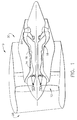
- FIG 2 is perspective view of a check valve 40 that may be used to regulate fluid flow on a gas turbine engine, such as engine 10 (shown in Figure 1). More specifically, in one embodiment, valve 40 is utilized within a cooling air supply system (not shown in Figure 2) to supply cooling air from a compressor, such as compressor 14 (shown in Figure 1) to a downstream engine sump (not shown). Valve 40 is hollow and includes a housing 42 including a downstream end 44, an upstream end 46, and a sidewall 50 extending therebetween.
- Housing downstream end 44 includes an integral flange 60 which may be used to couple valve 40 to an engine component (not shown).
- Flange 60 extends radially outwardly from a centerline axis of symmetry 64 of valve 40, such that flange 60 has an outer diameter 62 that is larger than an outer diameter (not shown in Figure 2) of housing upstream end 46.
- flange 60 is substantially circular.
- Flange 60 includes a pair of stops 66 that extend radially inwardly towards centerline axis of symmetry 64. Stops 66 are diametrically opposed and are identical.
- Housing upstream end 46 includes a lip 68 that is used to coupled valve 40 to a cooling supply duct or tube (not shown in Figure 2).
- lip 68 is substantially circular and is welded to the cooling supply duct. More specifically, lip 68 enables valve 40 to be coupled to the cooling supply duct such that an orientation of valve 40 with respect to the duct geometry is maintained.
- Sidewall 50 is substantially cylindrical and defines an opening 70 that extends between housing downstream and upstream end 44 and 46, respectively.
- opening 70 is substantially circular, and has a diameter 72 at each end 44 and 46.
- Sidewall 50 includes an interior surface 74 and an exterior surface 76.
- Valve opening 70 is defined by sidewall interior surface 74.
- a pair of recesses 80 are formed by sidewall 50.
- Recesses 80 are identical and are diametrically opposed. In the exemplary embodiment, recesses 80 are substantially aligned with respect to flange stops 66. Each recess 80 extends radially outwardly from valve centerline axis of symmetry 64. In the exemplary embodiment, each recess 80 has a substantially triangular cross-sectional profile.
- Each recess 80 includes a pair of openings 90 that extend through sidewall 50. More specifically, openings 90 are substantially aligned with respect to each other, and are each sized to receive a hinge pin 92 therethrough.
- a ledge 96 extends radially inward from sidewall 50. More specifically, ledge 96 extends radially inward from sidewall interior surface 74. Ledge 96 does not extend circumferentially within sidewall interior surface 74, but rather extends arcuately between recesses 80.
- a pair of control members or petals 100 are coupled to valve 40 within recesses 80.
- Members 100 are identical and are rotatably coupled to valve 40 with hinge pins 92. Accordingly, members 100 are rotatable between a fully- closed position (not shown in Figure 2) and a fully-open position (not shown in Figure 2). Accordingly, members 100 include a flapper portion 106 which extends across valve opening 70, and an attachment portion 110 which extends into each respective sidewall recess 80.
- Each control member portion 106 is substantially semi-circular and includes an upper surface 112 and a lower surface 114. Members 100 are contoured and accordingly, each portion 106 is not planar. In one embodiment, each member portion 106 is substantially semi-spherical. In the exemplary embodiment, each member lower surface 114 is contoured with respect to each member upper surface 112 such that a thickness 118 of each member portion 106 remains substantially capable of withstanding operating mechanical loads. A projection 119 extends from each control member upper surface 112 for contacting a respective flange stop 66 when a respective member 100 is in the fully-open position.
- Figure 3 is a plan view of check valve 40 viewed towards valve housing upstream end 46.
- Figure 4 is a cross-sectional schematic view of the check valve 40 coupled to a cooling air supply system 120. More specifically, within Figure 3, a control member 100 is in a fully-open position 122, and the other control member 100 is in a fully-closed position 124. When each control member 100 is in the fully-closed position 124, an outer perimeter portion 126 of each member portion 106 is positioned adjacent each respective sidewall ledge 96, and a center perimeter portion 128 extends substantially diametrically across valve opening 70. Center perimeter portion 128 includes a tapered outer edge 130 which enables the member center perimeter portions 128 of each respective member portion 106 to mate substantially flush against each other when members 100 are in the fully-closed position 124.
- each respective member projection 119 is positioned against each respective flange stop 66.
- Flange 60 has an outer diameter 62 that is larger than an outer diameter 140 of housing upstream end 46.
- the curved contour of each respective control member portion 106 facilitates increasing a valve effective area for valve 40 in comparison to valves which include substantially planar valve petals.
- cooling air supply system 120 includes a supply duct 152 used to route cooling air from a compressor, such as compressor 14 (shown in Figure 1) downstream to cooling plates (not shown) positioned downstream of a gas turbine engine sump (not shown).
- Duct 152 has a diameter 154 at an exit end 156 of duct 152 that is slightly smaller than an outer diameter 160 of housing upstream end 46. Accordingly, when housing upstream end lip 68 is welded to duct end 156, an orientation of valve 40 is fixed with respect to duct 152.
- valve upstream end 46 is only slightly larger than duct diameter 154, the design of valve 40 is considered compact, and existing engine hardware does not require modification to accommodate an increased diameter 140 of valve 40.
- each hinge pin 92 is inserted through a respective sidewall recess opening 90 and through a respective control member 100. Hinge pins 92 are then welded to securely couple each control member 100 within valve 40. In the exemplary embodiment, hinge pins 92 may be removed to facilitate replacing control members 100. Furthermore, because valve 40 is fixedly coupled to duct 152, the orientation of valve 40 is maintained, thus facilitating reducing valve petal flutter and failure, and increasing a useful life of valve 40.
- valve 40 During operation, as fluid flows downstream through supply duct 152 and into valve 40, fluid pressure forces control members 100 to rotate from fully-closed position 124 to open position 122. More specifically, fluid pressure forces each members 100 to rotate until each respective member projection 119 contacts a respective flange stop 66. Because each member portion 106 is curved, and because each member is coupled to valve 40 within a respective sidewall recess 80, a valve effective area is facilitated to be increased. Furthermore, the curved contour of each member 100 facilitates reducing fluid blockage through valve 40. As a result, pressure drops across valve 40 are facilitated to be reduced, and flow loss margins within valve 40 are facilitated to be maintained.
- control members 100 rotate to the fully-closed position 124 and fluid is substantially prevented from flowing upstream through valve 40, or from valve downstream end 44 to valve upstream end 46.
- the above-described check valve is cost-effective and highly reliable.
- the check valve includes a pair of control members that include contoured control members.
- the contoured control members define a blockage area within the valve that is smaller than that of other known check valves, and as such, facilitate reducing pressure losses of fluids flowing through the valve. Accordingly, the fluid is discharged from the check valve with reduced pressure drops across the valve. Furthermore, the check valve substantially prevents fluid from flowing upstream through the valve. As a result, a reliable and cost-effective check valve is provided.
Landscapes
- Engineering & Computer Science (AREA)
- General Engineering & Computer Science (AREA)
- Mechanical Engineering (AREA)
- Chemical & Material Sciences (AREA)
- Combustion & Propulsion (AREA)
- Check Valves (AREA)
- Supercharger (AREA)
Abstract
Description
- This invention relates generally to gas turbine engines and more particularly, to cooling systems used to supply cooling air to gas turbine engine components.
- Gas turbine engines typically include cooling systems to supply cooling air to components exposed to high temperatures. For example, at least some known gas turbine engines include cooling systems which supply air to pressurized sumps. More specifically, within such engines, a pair of ducts are used to route cooling air from a compressor stage to cooling plates positioned within the sumps.
- During engine operation, the cooling air facilitates preventing an operating temperature of the cooling plates from increasing as a result of exposure to heat generated by the engine. The ducts may also be exposed to vibrational stresses induced by the engine during engine operation. Over time, continued exposure to the vibrational and thermal stresses may damage one of the cooling supply ducts. More specifically, such stresses may cause duct breaks. Depending on a severity of the damage to the duct, the cooling air may flow through the duct break rather than into the sump. Furthermore, because the sump is pressurized, cooling air supplied to the sump by the other duct may be exhausted from the sump through the broken duct, thus increasing an operating temperature of the cooling plates. Over time, continued exposure to the higher operating temperatures may damage the cooling plates.
- In one aspect of the present invention, a check valve is provided. The check valve includes a valve housing and at least one control member. The valve housing includes a sidewall and an opening extending therethrough. The sidewall defines the opening and includes at least one recess formed therein. Each control member is rotatably coupled to the valve housing within the sidewall recess, and each control member is configured to allow flow of fluid through the valve opening in a first direction. Each control member is further configured to substantially prevent flow of fluid through the valve opening in a second direction that is opposite the first direction.
- In another aspect of the invention, a method for operating a gas turbine engine is provided. The method includes directing fluid downstream from a cooling air supply duct through a check valve that includes a hollow valve housing including a sidewall that has a recess formed therein and at least one control member that is rotatably coupled to the check valve within the recess. The method also includes preventing fluid from flowing upstream into the supply duct with the check valve.
- In a further aspect, a gas turbine engine cooling air supply system is provided. The cooling air supply system includes a cooling air supply duct including an end, and a check valve. The check valve is coupled to the cooling air supply duct end and is configured to permit fluid flow from the cooling air supply duct while substantially preventing flufd flow into the cooling air supply duct, and includes a hollow valve housing and at least one control member. The valve housing includes a sidewall and an opening that extends therethrough. The sidewall defines the opening and includes at least one recess formed therein. The control member is rotatably coupled to the valve housing within the sidewall recess.
- An embodiment of the invention will now be described, by way of example, with reference to the accompanying drawings, in which:
- Figure 1 is a schematic illustration of a gas turbine engine;
- Figure 2 is perspective view of a check valve that may be used with the engine shown in Figure 1;
- Figure 3 is a plan view of the check valve shown in Figure 2; and
- Figure 4 is a cross-sectional schematic view of the check valve shown in Figure 2 and coupled to a cooling air supply duct.
-
- Figure 1 is a schematic illustration of a
gas turbine engine 10 including afan assembly 12, a high-pressure compressor 14, and acombustor 16.Engine 10 also includes a high-pressure turbine 18 and a low-pressure turbine 20.Engine 10 has anintake side 28 and anexhaust side 30. In one embodiment,engine 10 is a CF-34 engine commercially available from General Electric Aircraft Engines, Cincinnati, Ohio.Engine 10 includes a sump (not shown) which is pressurized and cooled with cooling air. In one embodiment, air is routed from a fourth stage ofcompressor 14 for cooling the sump. - In operation, air flows through
fan assembly 12 and compressed air is supplied tocompressor 14. The compressed air is delivered tocombustor 16. Airflow fromcombustor 16drives turbines turbine 20drives fan assembly 12. - Figure 2 is perspective view of a
check valve 40 that may be used to regulate fluid flow on a gas turbine engine, such as engine 10 (shown in Figure 1). More specifically, in one embodiment,valve 40 is utilized within a cooling air supply system (not shown in Figure 2) to supply cooling air from a compressor, such as compressor 14 (shown in Figure 1) to a downstream engine sump (not shown). Valve 40 is hollow and includes ahousing 42 including adownstream end 44, anupstream end 46, and asidewall 50 extending therebetween. - Housing
downstream end 44 includes anintegral flange 60 which may be used to couplevalve 40 to an engine component (not shown).Flange 60 extends radially outwardly from a centerline axis ofsymmetry 64 ofvalve 40, such thatflange 60 has anouter diameter 62 that is larger than an outer diameter (not shown in Figure 2) of housing upstreamend 46. In the exemplary embodiment,flange 60 is substantially circular.Flange 60 includes a pair ofstops 66 that extend radially inwardly towards centerline axis ofsymmetry 64.Stops 66 are diametrically opposed and are identical. - Housing upstream
end 46 includes alip 68 that is used to coupledvalve 40 to a cooling supply duct or tube (not shown in Figure 2). In the exemplary embodiment,lip 68 is substantially circular and is welded to the cooling supply duct. More specifically,lip 68 enablesvalve 40 to be coupled to the cooling supply duct such that an orientation ofvalve 40 with respect to the duct geometry is maintained. -
Sidewall 50 is substantially cylindrical and defines an opening 70 that extends between housing downstream and upstreamend housing ends diameter 72 at eachend Sidewall 50 includes aninterior surface 74 and anexterior surface 76.Valve opening 70 is defined by sidewallinterior surface 74. - A pair of
recesses 80 are formed bysidewall 50.Recesses 80 are identical and are diametrically opposed. In the exemplary embodiment,recesses 80 are substantially aligned with respect toflange stops 66. Eachrecess 80 extends radially outwardly from valve centerline axis ofsymmetry 64. In the exemplary embodiment, eachrecess 80 has a substantially triangular cross-sectional profile. Eachrecess 80 includes a pair ofopenings 90 that extend throughsidewall 50. More specifically,openings 90 are substantially aligned with respect to each other, and are each sized to receive ahinge pin 92 therethrough. - A
ledge 96 extends radially inward fromsidewall 50. More specifically,ledge 96 extends radially inward from sidewallinterior surface 74.Ledge 96 does not extend circumferentially within sidewallinterior surface 74, but rather extends arcuately betweenrecesses 80. - A pair of control members or
petals 100 are coupled tovalve 40 withinrecesses 80.Members 100 are identical and are rotatably coupled tovalve 40 with hinge pins 92. Accordingly,members 100 are rotatable between a fully- closed position (not shown in Figure 2) and a fully-open position (not shown in Figure 2). Accordingly,members 100 include aflapper portion 106 which extends acrossvalve opening 70, and anattachment portion 110 which extends into eachrespective sidewall recess 80. - Each
control member portion 106 is substantially semi-circular and includes anupper surface 112 and alower surface 114.Members 100 are contoured and accordingly, eachportion 106 is not planar. In one embodiment, eachmember portion 106 is substantially semi-spherical. In the exemplary embodiment, each memberlower surface 114 is contoured with respect to each memberupper surface 112 such that athickness 118 of eachmember portion 106 remains substantially capable of withstanding operating mechanical loads. Aprojection 119 extends from each control memberupper surface 112 for contacting a respective flange stop 66 when arespective member 100 is in the fully-open position. - Figure 3 is a plan view of
check valve 40 viewed towards valve housingupstream end 46. Figure 4 is a cross-sectional schematic view of thecheck valve 40 coupled to a coolingair supply system 120. More specifically, within Figure 3, acontrol member 100 is in a fully-open position 122, and theother control member 100 is in a fully-closedposition 124. When eachcontrol member 100 is in the fully-closedposition 124, anouter perimeter portion 126 of eachmember portion 106 is positioned adjacent eachrespective sidewall ledge 96, and acenter perimeter portion 128 extends substantially diametrically acrossvalve opening 70.Center perimeter portion 128 includes a taperedouter edge 130 which enables the membercenter perimeter portions 128 of eachrespective member portion 106 to mate substantially flush against each other whenmembers 100 are in the fully-closedposition 124. - When each
control member 100 is in the fully-open position 122, eachrespective member projection 119 is positioned against eachrespective flange stop 66.Flange 60 has anouter diameter 62 that is larger than anouter diameter 140 of housingupstream end 46. Moreover, when eachcontrol member 100 is in the fully-open position 122, the curved contour of each respectivecontrol member portion 106 facilitates increasing a valve effective area forvalve 40 in comparison to valves which include substantially planar valve petals. -
Valve 40 is then coupled within a coolingair supply system 120 to supply cooling air to downstream engine components (not shown). More specifically, in the exemplary embodiment, coolingair supply system 120 includes asupply duct 152 used to route cooling air from a compressor, such as compressor 14 (shown in Figure 1) downstream to cooling plates (not shown) positioned downstream of a gas turbine engine sump (not shown).Duct 152 has adiameter 154 at anexit end 156 ofduct 152 that is slightly smaller than anouter diameter 160 of housingupstream end 46. Accordingly, when housingupstream end lip 68 is welded toduct end 156, an orientation ofvalve 40 is fixed with respect toduct 152. Moreover, because valveupstream end 46 is only slightly larger thanduct diameter 154, the design ofvalve 40 is considered compact, and existing engine hardware does not require modification to accommodate an increaseddiameter 140 ofvalve 40. - During assembly of
valve 40, eachhinge pin 92 is inserted through a respectivesidewall recess opening 90 and through arespective control member 100. Hinge pins 92 are then welded to securely couple eachcontrol member 100 withinvalve 40. In the exemplary embodiment, hinge pins 92 may be removed to facilitate replacingcontrol members 100. Furthermore, becausevalve 40 is fixedly coupled toduct 152, the orientation ofvalve 40 is maintained, thus facilitating reducing valve petal flutter and failure, and increasing a useful life ofvalve 40. - During operation, as fluid flows downstream through
supply duct 152 and intovalve 40, fluid pressure forces controlmembers 100 to rotate from fully-closedposition 124 to openposition 122. More specifically, fluid pressure forces eachmembers 100 to rotate until eachrespective member projection 119 contacts arespective flange stop 66. Because eachmember portion 106 is curved, and because each member is coupled tovalve 40 within arespective sidewall recess 80, a valve effective area is facilitated to be increased. Furthermore, the curved contour of eachmember 100 facilitates reducing fluid blockage throughvalve 40. As a result, pressure drops acrossvalve 40 are facilitated to be reduced, and flow loss margins withinvalve 40 are facilitated to be maintained. - Furthermore, when fluid flow is reversed through a
supply duct 152, or if a supply duct fails upstream fromvalve 40,control members 100 rotate to the fully-closedposition 124 and fluid is substantially prevented from flowing upstream throughvalve 40, or from valvedownstream end 44 to valveupstream end 46. - The above-described check valve is cost-effective and highly reliable. The check valve includes a pair of control members that include contoured control members. The contoured control members define a blockage area within the valve that is smaller than that of other known check valves, and as such, facilitate reducing pressure losses of fluids flowing through the valve. Accordingly, the fluid is discharged from the check valve with reduced pressure drops across the valve. Furthermore, the check valve substantially prevents fluid from flowing upstream through the valve. As a result, a reliable and cost-effective check valve is provided.
- For completeness, various aspects of the invention are set out in the following numbered clauses:
- 1. A method for operating a gas turbine engine (10), said method
comprising:
- directing fluid downstream from a cooling air supply duct (152) through a check valve (40) that includes a hollow valve housing (42) including a sidewall (50) that has a recess (80) formed therein and at least one control member (100) that is rotatably coupled to the check valve within the recess; and
- preventing fluid from flowing upstream into the supply duct with the check valve.
- 2. A method in accordance with Clause 1 wherein directing fluid downstream from a cooling air supply duct (152) through a check valve (40) further comprises directing fluid through a check valve including at least one control member (100) that facilitates reducing system pressure drop through the check valve.
- 3. A method in accordance with Clause 1 wherein directing fluid downstream from a cooling air supply duct (152) through a check valve (40) further comprises directing fluid through a check valve including at least one control member (100) that facilitates increasing a valve effective area through the check valve.
- 4. A method in accordance with Clause 1 wherein directing fluid downstream from a cooling air supply duct (152) through a check valve (40) further comprises directing fluid through a check valve including at least one control member (100) including a contoured upstream side (46) and a contoured downstream side (44).
- 5. A method in accordance with Clause 4 wherein directing fluid downstream from a cooling air supply duct (152) through a check valve (40) further comprises directing fluid through a check valve including a pair of mating control members (100).
- 6. A check valve (40) comprising:
- a valve housing (42) comprising a sidewall (50) and an opening (70) extending therethrough, said sidewall defining said opening and comprising at least one recess (80) therein;
- and at least one control member (100) rotatably coupled to said valve housing within said sidewall recess, said control member configured to allow flow of fluid through said valve opening in a first direction, and further configured to substantially prevent flow of fluid through said valve opening in a second direction opposite said first direction.
- 7. A check valve (40) in accordance with Clause 6 wherein at least a portion (106) of each said control member (100) configured to be substantially flush against an inner surface (74) of said valve housing sidewall (50).
- 8. A check valve (40) in accordance with Clause 6 wherein at least a portion (106) of each said control member (100) configured to extend at least partially across said housing opening (70) to prevent fluid flow through said housing opening in said second direction.
- 9. A check valve (40) in accordance with Clause 6 wherein said at least one control member (100) comprises a first control member and a second control member, said first and second control members identical and configured to mate to substantially prevent flow of fluid through said valve opening (70) in said second direction.
- 10. A check valve (40) in accordance with Clause 6 wherein said opening (70) has a substantially circular cross-sectional profile, said at least one control member (100) comprises a first control member and an identical second control member.
- 11. A check valve (40) in accordance with Clause 6 wherein each said control member (100) has a substantially semi-circular cross-sectional profile.
- 12. A check valve (40) in accordance with Clause 6 wherein each said control member (100) comprises a lower surface (114) and an upper surface (112), at least one of said lower and upper surfaces contoured.
- 13. A check valve (40) in accordance with Clause 6 wherein said control member upper surface (112) substantially parallel with said control member lower surface (114).
- 14. A gas turbine engine cooling air supply system (120) comprising:
- a cooling air supply duct (152) comprising an end (156); and
- a check valve (40) coupled to said cooling air supply duct end and configured to permit fluid flow from said cooling air supply duct while substantially preventing fluid flow into said cooling air supply duct, said check valve comprising a hollow valve housing (42) and at least one control member (100), said valve housing comprising a sidewall (50) and an opening (72) extending therethrough, said sidewall defining said opening and comprising at least one recess (80) formed therein, said control member rotatably coupled to said valve housing within said sidewall recess.
- 15. A cooling air supply system (120) in accordance with
Clause 14 wherein each said check valve control member (100) comprises an upstream surface (112) and a downstream surface (114), at least one of said upstream and said downstream surfaces contoured. - 16. A cooling air supply system (120) in accordance with Clause 15 wherein at least a portion (106) of each check valve control member (100) is configured to be substantially flush against an inner surface (74) of said valve housing sidewall (50) when said control member is positioned to substantially prevent fluid flow into said cooling air supply duct (152).
- 17. A cooling air supply system (120) in accordance with Clause 15 wherein said at least one check valve control member (100) comprises a pair of identical control members (100) configured to mate to substantially prevent fluid flow into said cooling air supply duct (152).
- 18. A cooling air supply system (120) in accordance with Clause 17 wherein said check valve housing opening (70) is substantially circular, each said check valve control member (100) has a substantially semi-circular cross-sectional profile.
- 19. A cooling air supply system (120) in accordance with Clause 15 wherein each said check valve control member (100) comprises an upper surface (112) and a lower surface (114), at least one of said control member lower and upper surfaces contoured.
- 20. A cooling air supply system (20) in accordance with Clause 19 wherein each said check valve control member upper surface (112) substantially parallel with each said respective control member lower surface (114).
-
Claims (10)
- A method for operating a gas turbine engine (10), said method comprising:directing fluid downstream from a cooling air supply duct (152) through a check valve (40) that includes a hollow valve housing (42) including a sidewall (50) that has a recess (80) formed therein and at least one control member (100) that is rotatably coupled to the check valve within the recess; andpreventing fluid from flowing upstream into the supply duct with the check valve.
- A method in accordance with Claim 1 wherein directing fluid downstream from a cooling air supply duct (152) through a check valve (40) further comprises directing fluid through a check valve including at least one control member (100) that facilitates reducing system pressure drop through the check valve.
- A method in accordance with Claim 1 wherein directing fluid downstream from a cooling air supply duct (152) through a check valve (40) further comprises directing fluid through a check valve including at least one control member (100) that facilitates increasing a valve effective area through the check valve.
- A method in accordance with Claim 1 wherein directing fluid downstream from a cooling air supply duct (152) through a check valve (40) further comprises directing fluid through a check valve including at least one control member (100) including a contoured upstream side (46) and a contoured downstream side (44).
- A check valve (40) comprising:a valve housing (42) comprising a sidewall (50) and an opening (70) extending therethrough, said sidewall defining said opening and comprising at least one recess (80) therein;and at least one control member (100) rotatably coupled to said valve housing within said sidewall recess, said control member configured to allow flow of fluid through said valve opening in a first direction, and further configured to substantially prevent flow of fluid through said valve opening in a second direction opposite said first direction.
- A check valve (40) in accordance with Claim 5 wherein at least a portion (106) of each said control member (100) configured to be substantially flush against an inner surface (74) of said valve housing sidewall (50).
- A check valve (40) in accordance with Claim 5 wherein at least a portion (106) of each said control member (100) configured to extend at least partially across said housing opening (70) to prevent fluid flow through said housing opening in said second direction.
- A check valve (40) in accordance with Claim 5 wherein said at least one control member (100) comprises a first control member and a second control member, said first and second control members identical and configured to mate to substantially prevent flow of fluid through said valve opening (70) in said second direction.
- A check valve (40) in accordance with Claim 5 wherein said opening (70) has a substantially circular cross-sectional profile, said at least one control member (100) comprises a first control member and an identical second control member.
- A gas turbine engine cooling air supply system (120) comprising:a cooling air supply duct (152) comprising an end (156); anda check valve (40) coupled to said cooling air supply duct end and configured to permit fluid flow from said cooling air supply duct while substantially preventing fluid flow into said cooling air supply duct, said check valve comprising a hollow valve housing (42) and at least one control member (100), said valve housing comprising a sidewall (50) and an opening (72) extending therethrough, said sidewall defining said opening and comprising at least one recess (80) formed therein, said control member rotatably coupled to said valve housing within said sidewall recess.
Applications Claiming Priority (2)
| Application Number | Priority Date | Filing Date | Title |
|---|---|---|---|
| US09/999,272 US6659711B2 (en) | 2001-11-15 | 2001-11-15 | Methods and apparatus for regulating turbine cooling airflow supply systems |
| US999272 | 2001-11-15 |
Publications (2)
| Publication Number | Publication Date |
|---|---|
| EP1312763A1 true EP1312763A1 (en) | 2003-05-21 |
| EP1312763B1 EP1312763B1 (en) | 2005-11-16 |
Family
ID=25546117
Family Applications (1)
| Application Number | Title | Priority Date | Filing Date |
|---|---|---|---|
| EP02257912A Expired - Lifetime EP1312763B1 (en) | 2001-11-15 | 2002-11-15 | Valve for regulating turbine cooling airflow supply system |
Country Status (5)
| Country | Link |
|---|---|
| US (1) | US6659711B2 (en) |
| EP (1) | EP1312763B1 (en) |
| JP (1) | JP4229680B2 (en) |
| CN (1) | CN1273724C (en) |
| DE (1) | DE60207363T2 (en) |
Cited By (5)
| Publication number | Priority date | Publication date | Assignee | Title |
|---|---|---|---|---|
| EP1895212A1 (en) * | 2006-08-30 | 2008-03-05 | Honeywell International Inc. | Flapper with insert stops for check valve |
| US7493770B2 (en) | 2004-08-09 | 2009-02-24 | General Electric Company | Methods and apparatus for regulating airflow supply systems |
| EP1988315A3 (en) * | 2007-04-27 | 2011-03-02 | Hamilton Sundstrand Corporation | Fast acting aircraft engine bleed air check valve |
| FR2978224A1 (en) * | 2011-07-18 | 2013-01-25 | Ge Energy Products France Snc | Valve for ventilation duct in gas turbine, has flaps articulated about axes situated in two mutually opposing zones of cylindrical body, where flaps have shape complementary to that of body against which flaps rest in open position of valve |
| EP3193055A1 (en) * | 2016-01-15 | 2017-07-19 | Hamilton Sundstrand Corporation | Check valve |
Families Citing this family (9)
| Publication number | Priority date | Publication date | Assignee | Title |
|---|---|---|---|---|
| US20110150640A1 (en) * | 2003-08-21 | 2011-06-23 | Peter Tiemann | Labyrinth Seal in a Stationary Gas Turbine |
| KR101335882B1 (en) * | 2010-08-31 | 2013-12-02 | 김청균 | Alarm combination valve |
| CN103369914A (en) * | 2012-03-29 | 2013-10-23 | 鸿富锦精密工业(深圳)有限公司 | Wind resistance device and electronic product with wind resistance device |
| US9188010B2 (en) * | 2012-06-25 | 2015-11-17 | General Electric Company | Systems and methods to control flow in a rotor wheel |
| CN106401669A (en) * | 2015-07-31 | 2017-02-15 | 新乡航空工业(集团)有限公司 | Outlet runner structure of intermediate-stage turbine |
| US10005111B2 (en) | 2016-01-25 | 2018-06-26 | General Electric Company | Turbine engine cleaning systems and methods |
| US11359732B1 (en) * | 2021-04-07 | 2022-06-14 | Applied Materials, Inc. | Method and mechanism for symmetrically controlling pressure in process chamber |
| US11828372B2 (en) * | 2022-03-31 | 2023-11-28 | General Electric Company | Check valve assembly |
| CN116624289A (en) * | 2023-05-30 | 2023-08-22 | 中国航发沈阳发动机研究所 | Passive front duct ejector adjusting device of circulating variable aeroengine |
Citations (6)
| Publication number | Priority date | Publication date | Assignee | Title |
|---|---|---|---|---|
| US2831499A (en) * | 1954-09-07 | 1958-04-22 | Rohr Aircraft Corp | Check valve |
| US2956582A (en) * | 1958-09-02 | 1960-10-18 | Lawrence A Pranter | Valve |
| US3445863A (en) * | 1965-12-08 | 1969-05-27 | Juro Wada | One-way valve device suitable for use as a heart valve |
| FR2584162A1 (en) * | 1985-06-26 | 1987-01-02 | Alsthom Atlantique | Non-return valve with multiple inner capsules, intended especially for lifting installations |
| JPH09280072A (en) * | 1996-04-17 | 1997-10-28 | Hitachi Ltd | Air / steam cooling gas turbine system |
| DE29807895U1 (en) * | 1998-05-02 | 1998-08-06 | Jakob Handte & Co GmbH, 78532 Tuttlingen | Pressure relief flap |
Family Cites Families (9)
| Publication number | Priority date | Publication date | Assignee | Title |
|---|---|---|---|---|
| US4178638A (en) * | 1977-08-01 | 1979-12-18 | Louis C. Meyer | Split leaflet check valves |
| US4813481A (en) * | 1987-08-27 | 1989-03-21 | Otis Engineering Corporation | Expendable flapper valve |
| US5044396A (en) * | 1990-06-18 | 1991-09-03 | Daudet Howard C | Check valve for fluids |
| US5078739A (en) * | 1990-07-20 | 1992-01-07 | Janus Biomedical, Inc. | Bileaflet heart valve with external leaflets |
| US5176171A (en) | 1991-10-17 | 1993-01-05 | Flomatic Corporation | Check valve |
| US5318407A (en) | 1992-09-08 | 1994-06-07 | Foppe Thelen Group, Inc. | Check valve having internal float |
| US5356268A (en) | 1993-09-29 | 1994-10-18 | The Nash Engineering Company | Check valve structures for liquid ring pumps |
| USD364210S (en) | 1994-07-19 | 1995-11-14 | Drummond Industries | Transparent sump pump check valve |
| US6050079A (en) * | 1997-12-24 | 2000-04-18 | General Electric Company | Modulated turbine cooling system |
-
2001
- 2001-11-15 US US09/999,272 patent/US6659711B2/en not_active Expired - Lifetime
-
2002
- 2002-11-14 JP JP2002330341A patent/JP4229680B2/en not_active Expired - Fee Related
- 2002-11-15 CN CNB021495882A patent/CN1273724C/en not_active Expired - Fee Related
- 2002-11-15 DE DE60207363T patent/DE60207363T2/en not_active Expired - Lifetime
- 2002-11-15 EP EP02257912A patent/EP1312763B1/en not_active Expired - Lifetime
Patent Citations (6)
| Publication number | Priority date | Publication date | Assignee | Title |
|---|---|---|---|---|
| US2831499A (en) * | 1954-09-07 | 1958-04-22 | Rohr Aircraft Corp | Check valve |
| US2956582A (en) * | 1958-09-02 | 1960-10-18 | Lawrence A Pranter | Valve |
| US3445863A (en) * | 1965-12-08 | 1969-05-27 | Juro Wada | One-way valve device suitable for use as a heart valve |
| FR2584162A1 (en) * | 1985-06-26 | 1987-01-02 | Alsthom Atlantique | Non-return valve with multiple inner capsules, intended especially for lifting installations |
| JPH09280072A (en) * | 1996-04-17 | 1997-10-28 | Hitachi Ltd | Air / steam cooling gas turbine system |
| DE29807895U1 (en) * | 1998-05-02 | 1998-08-06 | Jakob Handte & Co GmbH, 78532 Tuttlingen | Pressure relief flap |
Non-Patent Citations (1)
| Title |
|---|
| PATENT ABSTRACTS OF JAPAN vol. 1998, no. 02 30 January 1998 (1998-01-30) * |
Cited By (7)
| Publication number | Priority date | Publication date | Assignee | Title |
|---|---|---|---|---|
| US7493770B2 (en) | 2004-08-09 | 2009-02-24 | General Electric Company | Methods and apparatus for regulating airflow supply systems |
| EP1895212A1 (en) * | 2006-08-30 | 2008-03-05 | Honeywell International Inc. | Flapper with insert stops for check valve |
| US7779859B2 (en) | 2006-08-30 | 2010-08-24 | Honeywell International Inc. | Flapper with insert stops for check valve |
| EP1988315A3 (en) * | 2007-04-27 | 2011-03-02 | Hamilton Sundstrand Corporation | Fast acting aircraft engine bleed air check valve |
| FR2978224A1 (en) * | 2011-07-18 | 2013-01-25 | Ge Energy Products France Snc | Valve for ventilation duct in gas turbine, has flaps articulated about axes situated in two mutually opposing zones of cylindrical body, where flaps have shape complementary to that of body against which flaps rest in open position of valve |
| EP3193055A1 (en) * | 2016-01-15 | 2017-07-19 | Hamilton Sundstrand Corporation | Check valve |
| US10344882B2 (en) | 2016-01-15 | 2019-07-09 | Hamilton Sundstrand Corporation | Check valve |
Also Published As
| Publication number | Publication date |
|---|---|
| EP1312763B1 (en) | 2005-11-16 |
| DE60207363T2 (en) | 2006-07-27 |
| US20030091428A1 (en) | 2003-05-15 |
| JP4229680B2 (en) | 2009-02-25 |
| CN1420262A (en) | 2003-05-28 |
| US6659711B2 (en) | 2003-12-09 |
| DE60207363D1 (en) | 2005-12-22 |
| CN1273724C (en) | 2006-09-06 |
| JP2003193864A (en) | 2003-07-09 |
Similar Documents
| Publication | Publication Date | Title |
|---|---|---|
| US6659711B2 (en) | Methods and apparatus for regulating turbine cooling airflow supply systems | |
| US7493770B2 (en) | Methods and apparatus for regulating airflow supply systems | |
| CN108457705B (en) | Method and system for joining ceramic matrix composite material member to metal member | |
| CA2503930C (en) | Gas turbine engine variable vane assembly | |
| US8092176B2 (en) | Turbine airfoil cooling system with curved diffusion film cooling hole | |
| EP1947298B1 (en) | Slider seal assembly for gas turbine engine | |
| CN101424290B (en) | Fully contained retaining pins for turbine nozzles | |
| US6146093A (en) | Variable vane seal and washer | |
| EP2955330A2 (en) | Cooling systems for gas turbine engine components | |
| US6808364B2 (en) | Methods and apparatus for sealing gas turbine engine variable vane assemblies | |
| CN110872985B (en) | Retaining ring for a turbine engine | |
| US7434405B2 (en) | Bleed diffuser for gas turbine engine | |
| EP3722564A1 (en) | Vane arm assembly for a gas turbine engine, corresponding method of redundantly axially retaining a vane arm, and gas turbine engine | |
| US11162381B2 (en) | Turbocharger | |
| CN100379944C (en) | Nozzle lock and gas turbine engine and method of securing engine nozzles | |
| CN115522984B (en) | Attachment structure for airfoil belt | |
| EP3699400B1 (en) | Gas turbine engine system with light weight low blockage slider seal | |
| US20040187472A1 (en) | Method and system for reducing turbine exhaust turbulence | |
| EP4328419B1 (en) | Exhaust assembly for purging a nacelle cavity of a propulsion system |
Legal Events
| Date | Code | Title | Description |
|---|---|---|---|
| PUAI | Public reference made under article 153(3) epc to a published international application that has entered the european phase |
Free format text: ORIGINAL CODE: 0009012 |
|
| AK | Designated contracting states |
Designated state(s): AT BE BG CH CY CZ DE DK EE ES FI FR GB GR IE IT LI LU MC NL PT SE SK TR |
|
| AX | Request for extension of the european patent |
Extension state: AL LT LV MK RO SI |
|
| 17P | Request for examination filed |
Effective date: 20031121 |
|
| AKX | Designation fees paid |
Designated state(s): DE FR GB |
|
| 17Q | First examination report despatched |
Effective date: 20040310 |
|
| GRAP | Despatch of communication of intention to grant a patent |
Free format text: ORIGINAL CODE: EPIDOSNIGR1 |
|
| RTI1 | Title (correction) |
Free format text: VALVE FOR REGULATING TURBINE COOLING AIRFLOW SUPPLY SYSTEM |
|
| GRAS | Grant fee paid |
Free format text: ORIGINAL CODE: EPIDOSNIGR3 |
|
| GRAA | (expected) grant |
Free format text: ORIGINAL CODE: 0009210 |
|
| AK | Designated contracting states |
Kind code of ref document: B1 Designated state(s): DE FR GB |
|
| REG | Reference to a national code |
Ref country code: GB Ref legal event code: FG4D |
|
| REF | Corresponds to: |
Ref document number: 60207363 Country of ref document: DE Date of ref document: 20051222 Kind code of ref document: P |
|
| ET | Fr: translation filed | ||
| PLBE | No opposition filed within time limit |
Free format text: ORIGINAL CODE: 0009261 |
|
| STAA | Information on the status of an ep patent application or granted ep patent |
Free format text: STATUS: NO OPPOSITION FILED WITHIN TIME LIMIT |
|
| 26N | No opposition filed |
Effective date: 20060817 |
|
| REG | Reference to a national code |
Ref country code: FR Ref legal event code: PLFP Year of fee payment: 14 |
|
| PGFP | Annual fee paid to national office [announced via postgrant information from national office to epo] |
Ref country code: GB Payment date: 20151127 Year of fee payment: 14 Ref country code: DE Payment date: 20151127 Year of fee payment: 14 |
|
| PGFP | Annual fee paid to national office [announced via postgrant information from national office to epo] |
Ref country code: FR Payment date: 20151117 Year of fee payment: 14 |
|
| REG | Reference to a national code |
Ref country code: DE Ref legal event code: R119 Ref document number: 60207363 Country of ref document: DE |
|
| GBPC | Gb: european patent ceased through non-payment of renewal fee |
Effective date: 20161115 |
|
| REG | Reference to a national code |
Ref country code: FR Ref legal event code: ST Effective date: 20170731 |
|
| PG25 | Lapsed in a contracting state [announced via postgrant information from national office to epo] |
Ref country code: FR Free format text: LAPSE BECAUSE OF NON-PAYMENT OF DUE FEES Effective date: 20161130 |
|
| PG25 | Lapsed in a contracting state [announced via postgrant information from national office to epo] |
Ref country code: DE Free format text: LAPSE BECAUSE OF NON-PAYMENT OF DUE FEES Effective date: 20170601 Ref country code: GB Free format text: LAPSE BECAUSE OF NON-PAYMENT OF DUE FEES Effective date: 20161115 |