EP1312758A2 - Methods and apparatus for cooling gas turbine nozzles - Google Patents
Methods and apparatus for cooling gas turbine nozzles Download PDFInfo
- Publication number
- EP1312758A2 EP1312758A2 EP02257901A EP02257901A EP1312758A2 EP 1312758 A2 EP1312758 A2 EP 1312758A2 EP 02257901 A EP02257901 A EP 02257901A EP 02257901 A EP02257901 A EP 02257901A EP 1312758 A2 EP1312758 A2 EP 1312758A2
- Authority
- EP
- European Patent Office
- Prior art keywords
- airfoil
- sidewall
- insert
- nozzle
- vane
- Prior art date
- Legal status (The legal status is an assumption and is not a legal conclusion. Google has not performed a legal analysis and makes no representation as to the accuracy of the status listed.)
- Withdrawn
Links
Images


Classifications
-
- F—MECHANICAL ENGINEERING; LIGHTING; HEATING; WEAPONS; BLASTING
- F01—MACHINES OR ENGINES IN GENERAL; ENGINE PLANTS IN GENERAL; STEAM ENGINES
- F01D—NON-POSITIVE DISPLACEMENT MACHINES OR ENGINES, e.g. STEAM TURBINES
- F01D25/00—Component parts, details, or accessories, not provided for in, or of interest apart from, other groups
- F01D25/08—Cooling; Heating; Heat-insulation
- F01D25/12—Cooling
-
- F—MECHANICAL ENGINEERING; LIGHTING; HEATING; WEAPONS; BLASTING
- F01—MACHINES OR ENGINES IN GENERAL; ENGINE PLANTS IN GENERAL; STEAM ENGINES
- F01D—NON-POSITIVE DISPLACEMENT MACHINES OR ENGINES, e.g. STEAM TURBINES
- F01D5/00—Blades; Blade-carrying members; Heating, heat-insulating, cooling or antivibration means on the blades or the members
- F01D5/12—Blades
- F01D5/14—Form or construction
- F01D5/18—Hollow blades, i.e. blades with cooling or heating channels or cavities; Heating, heat-insulating or cooling means on blades
- F01D5/187—Convection cooling
- F01D5/188—Convection cooling with an insert in the blade cavity to guide the cooling fluid, e.g. forming a separation wall
- F01D5/189—Convection cooling with an insert in the blade cavity to guide the cooling fluid, e.g. forming a separation wall the insert having a tubular cross-section, e.g. airfoil shape
-
- F—MECHANICAL ENGINEERING; LIGHTING; HEATING; WEAPONS; BLASTING
- F01—MACHINES OR ENGINES IN GENERAL; ENGINE PLANTS IN GENERAL; STEAM ENGINES
- F01D—NON-POSITIVE DISPLACEMENT MACHINES OR ENGINES, e.g. STEAM TURBINES
- F01D9/00—Stators
- F01D9/02—Nozzles; Nozzle boxes; Stator blades; Guide conduits, e.g. individual nozzles
-
- F—MECHANICAL ENGINEERING; LIGHTING; HEATING; WEAPONS; BLASTING
- F05—INDEXING SCHEMES RELATING TO ENGINES OR PUMPS IN VARIOUS SUBCLASSES OF CLASSES F01-F04
- F05D—INDEXING SCHEME FOR ASPECTS RELATING TO NON-POSITIVE-DISPLACEMENT MACHINES OR ENGINES, GAS-TURBINES OR JET-PROPULSION PLANTS
- F05D2260/00—Function
- F05D2260/20—Heat transfer, e.g. cooling
- F05D2260/201—Heat transfer, e.g. cooling by impingement of a fluid
-
- Y—GENERAL TAGGING OF NEW TECHNOLOGICAL DEVELOPMENTS; GENERAL TAGGING OF CROSS-SECTIONAL TECHNOLOGIES SPANNING OVER SEVERAL SECTIONS OF THE IPC; TECHNICAL SUBJECTS COVERED BY FORMER USPC CROSS-REFERENCE ART COLLECTIONS [XRACs] AND DIGESTS
- Y02—TECHNOLOGIES OR APPLICATIONS FOR MITIGATION OR ADAPTATION AGAINST CLIMATE CHANGE
- Y02T—CLIMATE CHANGE MITIGATION TECHNOLOGIES RELATED TO TRANSPORTATION
- Y02T50/00—Aeronautics or air transport
- Y02T50/60—Efficient propulsion technologies, e.g. for aircraft
Definitions
- This invention relates generally to gas turbine engine nozzles and more particularly, to methods and apparatus for cooling gas turbine engine nozzles.
- Gas turbine engines include combustors which ignite fuel-air mixtures which are then channeled through a turbine nozzle assembly towards a turbine.
- At least some known turbine nozzle assemblies include a plurality of nozzles arranged circumferentially and configured as doublets.
- a turbine nozzle doublet includes a pair of circumferentially-spaced hollow airfoil vanes coupled by integrally-formed inner and outer band platforms.
- the doublet type turbine nozzles facilitate improving durability and reducing leakage in comparison to non-doublet turbine nozzles. Furthermore, turbine nozzle doublets also facilitate reducing manufacturing and assembly costs. In addition, because such turbine nozzles are subjected to high temperatures and may be subjected to high mechanical loads, at least some known doublets include an identical insert installed within each airfoil vane cavity to distribute cooling air supplied internally to each airfoil vane. The inserts include a plurality of openings extending through each side of the insert.
- the temperature of the external gas is higher on the pressure-side than on the suction-side of each airfoil vane. Because the openings are arranged symmetrically between the opposite insert sides, the openings facilitate distributing the cooling air throughout the airfoil vane cavity to facilitate achieving approximately the same operating temperature on opposite sides of each airfoil.
- mechanical loads and thermal stresses may still be induced unequally across the turbine nozzle.
- typically the mechanical and thermal stresses induced to the trailing doublet airfoil vane are higher than those induced to the leading doublet airfoil vane. Over time, continued operation with an unequal distribution of stresses within the nozzle may shorten a useful life of the nozzle.
- a method for assembling a turbine nozzle for a gas turbine engine includes providing a hollow doublet including a leading airfoil vane and a trailing airfoil vane coupled by at least one platform, wherein each airfoil vane includes a first sidewall and a second sidewall that extend between a respective leading and trailing edge.
- the method also includes inserting a first insert into the lead airfoil vane, wherein the insert includes a first sidewall including a first plurality of cooling openings that extend therethrough, and a second sidewall including a second plurality of cooling openings extending therethrough.
- the method also includes inserting a second insert into the trailing airfoil vane, wherein the first and second inserts are identical and are configured to configured to facilitate cooling each respective airfoil vane first sidewall more than each respective airfoil vane second sidewall.
- a method of operating a gas turbine engine includes directing fluid flow through the engine using at least one turbine airfoil nozzle that includes a leading airfoil and a trailing airfoil coupled by at least one platform that is formed integrally with the leading and trailing airfoils, and wherein each respective airfoil includes a first sidewall and a second sidewall that extend between respective leading and trailing edges to define a cavity therein.
- the method also includes directing cooling air into the turbine airfoil nozzle through a pair of identical turbine nozzle inserts such that one side of each airfoil is cooled more than the other side of each airfoil.
- a turbine nozzle for a gas turbine engine includes a pair of identical airfoil vanes coupled by at least one platform formed integrally with the airfoil vanes.
- Each airfoil vane includes a first sidewall and a second sidewall that are connected at a leading edge and a trailing edge, such that a cavity is defined therebetween.
- the nozzle also includes a pair of identical inserts configured to be inserted within each airfoil vane cavity.
- Each insert includes a first sidewall and a second sidewall.
- Each insert first sidewall includes a first plurality of openings extending therethrough for directing cooling air towards at least one of each of the airfoil vane first and second sidewalls.
- Each insert second sidewall includes a second plurality of openings extending therethrough for directing cooling air towards at least one of each of the airfoil vane first and second sidewalls, wherein the first plurality of openings are configured to cool each airfoil more the second plurality of cooling openings cool each airfoil.
- Figure 1 is a schematic illustration of a gas turbine engine 10 including a fan assembly 12, a high-pressure compressor 14, and a combustor 16.
- Engine 10 also includes a high-pressure turbine 18 and a low-pressure turbine 20.
- Engine 10 has an intake, or upstream, side 28 and an exhaust, or downstream, side 30.
- engine 10 is a CF6-80 engine commercially available from General Electric Aircraft Engines, Cincinnati, Ohio.
- Airflow from combustor 16 is discharged through a turbine nozzle assembly (not shown in Figure 1) that includes a plurality of nozzles (not shown in Figure 1) and used to drive turbines 18 and 20.
- Turbine 20 in turn, drives fan assembly 12, and turbine 18 drives high-pressure compressor 14.
- FIG 2 is an exploded perspective forward-looking-aft view of turbine nozzle 50 that may be used with gas turbine engine 10 (shown in Figure 1).
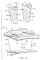
- Figure 3 is an exploded perspective aft-looking-forward view of turbine nozzle 50.
- Nozzle 50 is known as a doublet and includes a pair of circumferentially-spaced airfoil vanes 52 coupled together by an arcuate radially outer band or platform 54 and an arcuate radially inner band or platform 56. More specifically, in the exemplary embodiment, each band 54 and 56 is formed integrally with airfoil vanes 52.
- Inner band 54 includes a retention flange 60 that extends radially inwardly therefrom. More specifically, flange 60 extends substantially perpendicularly from band 54 with respect to a radially outer surface 62 of flange 60.
- Outer band 56 also includes a retention flange 64 that extends radially outwardly therefrom, and a leading edge flange 66 that also extends radially outwardly therefrom. More specifically, outer band retention flange 64 and leading edge flange 66 extend substantially perpendicularly from band 56 with respect to a radially inner surface 68 of band 56. Surfaces 62 and 68 define a radially outer and radially inner boundary for a flowpath through nozzle 50.
- Airfoil vanes 52 are identical and include a leading airfoil vane 76 and a trailing airfoil vane 78.
- Each airfoil vane 52 includes a first sidewall 80 and a second sidewall 82.
- First sidewall 80 is convex and defines a suction side of each airfoil vane 76 and 78
- second sidewall 82 is concave and defines a pressure side of each airfoil vane 76 and 78.
- Sidewalls 80 and 82 are joined at a leading edge 84 and at an axially-spaced trailing edge 86 of each airfoil vane 76 and 78. More specifically, each airfoil trailing edge 86 is spaced chordwise and downstream from each respective airfoil leading edge 84.
- First and second sidewalls 80 and 82 extend longitudinally, or radially outwardly, in span from radially inner band 54 to radially outer band 56. Additionally, first and second sidewalls 80 and 82, respectively, define a cooling chamber 90 within each airfoil vane 52. More specifically, chamber 90 is bounded by an inner surface 92 and 94 of each respective sidewall 80 and 82, and extends through each band 54 and 56.
- Each cooling chamber 90 is sized to receive an insert 100 therein. More specifically, lead airfoil chamber 90 is sized to receive a lead insert 102, and trailing airfoil chamber 90 is sized to receive a trailing insert 104 therein.
- Inserts 102 and 104 are identical and each includes a key feature 110 and an attachment flange 114.
- Flange 114 extends from a radially outer end 116 of each insert 100, and enables each insert 100 to be secured within each respective cooling chamber 90.
- flange 114 is brazed to radially outer band 56.
- flange 114 is welded to radially outer band 56.
- Key features 110 extend through flange 114 at each insert radially outer end 116, and are sized to be received in a mating slot (not shown) that extends through nozzle radially outer band 56. More specifically, key features 110 facilitate inserts 100 being installed in a proper orientation within chamber 90 and with respect to each airfoil vane 52.
- Each insert 100 has a cross sectional profile that is substantially similar to that of each airfoil vane 52. More specifically, each insert 100 includes a first sidewall 120 and a second sidewall 124. Each insert first sidewall 120 is convex and defines a suction side of each insert 100, and each insert second sidewall is concave and defines a pressure side of each insert 102 and 104. Accordingly, each insert first sidewall 120 is adjacent each respective airfoil vane first sidewall 80 when each insert 102 and 104 is installed within each respective cooling chamber 90. Sidewalls 120 and 124 are joined at a leading edge 128 and at a trailing edge 132.
- Each first sidewall 120 defines a suction side of each insert 100 and includes a first plurality of openings 140 that extend therethrough to a cavity 142 defined therein.
- Each second sidewall 124 includes a second plurality of openings 144 that extend therethrough to cavity 142.
- Each insert 100 is biased to facilitate cooling a suction side 80 of each airfoil vane 52 more than a pressure side 82 of each airfoil vane 52 more than a pressure side 82 of each airfoil vane 52.
- the plurality of first sidewall openings 140 are greater than that required to achieve substantially equal airfoil vane surface temperatures when compared to the plurality of second sidewall openings 144.
- each first sidewall 120 includes one hundred four first sidewall openings 140
- each second sidewall 124 includes one hundred and nine openings 144.
- the larger volume of air is facilitated because each insert first sidewall 120 includes openings 140 which are larger in diameter than corresponding openings 144 extending through insert second sidewall 124. It should be noted that the arrangement of openings 140 and 144 with respect to each respective sidewall 120 and 124 is variable. Furthermore, the number and size of openings 140 and 144 is also variable.
- Each nozzle 50 is in flow communication with a cooling system (not shown) that directs cooling air into each airfoil vane cooling chamber 90 for internal cooling of nozzle airfoil vanes 52.
- the cooling system directs cooling air into each airfoil vane insert 100, which in-turn, channels the cooling air for cooling airfoil vanes 52.
- cooling air is routed through the cooling system into nozzles 50, which may not be thermally loaded or mechanically stressed equally between adjacent airfoil vanes 76 and 78. More specifically, due to gas loading, thermal variations, and mechanical loading, more mechanical and thermal stresses are induced and transmitted through trailing airfoil vane 78 than through lead airfoil vane 76. Cooling air supplied to nozzle 50 is biased more to a suction side 80 of each airfoil vane 52 than to a pressure side 82 of each airfoil vane 52. More specifically, as cooling air is channeled into nozzle 50, inserts 100 direct cooling air towards each respective nozzle airfoil vane 76 and 78.
- each nozzle airfoil vane 52 exits outwardly from each nozzle airfoil vane 52 through a plurality of airfoil trailing edge openings (not shown), and thermal stresses induced within each individual airfoil vane 52 are facilitated to be reduced.
- a maximum temperature of each airfoil vane concave surface 82 is increased, the thermal stresses induced in nozzle 50 are facilitated to be controlled to counteract the mechanical stresses, thus facilitating increasing a useful life of nozzle 50.
- the above-described turbine nozzle includes a pair of identical inserts that enable a cooling scheme for the nozzle to be altered to optimize cooling of turbine nozzle doublets.
- the inserts bias the distribution of cooling air supplied to the nozzle more to the suction side of each of the airfoil vanes.
- the inserts facilitate controlling thermal stresses induced within the nozzle, and thus, facilitate increasing the useful life of the nozzle in a cost-effective and reliable manner.
Landscapes
- Engineering & Computer Science (AREA)
- Mechanical Engineering (AREA)
- General Engineering & Computer Science (AREA)
- Turbine Rotor Nozzle Sealing (AREA)
Abstract
Description
Claims (10)
- A method for assembling a turbine nozzle (50) for a gas turbine engine (10), said method comprising:providing a hollow turbine nozzle including a leading airfoil vane (76) and a trailing airfoil vane (78) coupled by at least one platform (54) that is formed integrally with the airfoil vanes, and wherein each airfoil vane includes a first sidewall (80) and a second sidewall (82) connected at a leading edge (84) and a trailing edge (86),inserting a first insert (102) into the leading airfoil vane that includes a first sidewall (120) including a first plurality of cooling openings (140) extending therethrough, and a second sidewall (124) including a second plurality of cooling openings (144) extending therethrough; andinserting a second insert (104) into the trailing airfoil vane, wherein the first insert and the second inserts are identical and are configured to facilitate cooling each respective airfoil vane first sidewall more than each respective airfoil vane second sidewall.
- A method in accordance with Claim 1 wherein the first sidewall (80) of each airfoil vane (52) is convex, and the second sidewall (82) of each airfoil vane is concave, inserting a first insert (102) into the leading airfoil vane (76) further comprises inserting the first insert into the first airfoil vane to facilitate biasing cooling airflow towards the convex side of the airfoil vane.
- A method of operating a gas turbine engine (50), said method comprising:directing fluid flow through the engine using at least one turbine airfoil nozzle (50) that includes a leading airfoil (76) and a trailing airfoil (78) coupled by at least one platform (54) that is formed integrally with the leading and trailing airfoils, and wherein each respective airfoil includes a first sidewall (80) and a second sidewall (82) that extend between respective leading and trailing edges (84, 86) to define a cavity (142) therein; anddirecting cooling air into the turbine airfoil nozzle through a pair of identical turbine nozzle inserts (100) such that one side of each airfoil is cooled more than the other side of each airfoil.
- A method in accordance with Claim 3 wherein directing cooling air into the turbine airfoil nozzle (50) through a pair of identical turbine nozzle inserts (100) further comprises directing airflow into each respective airfoil cavity (142) through the pair of identical inserts installed within the turbine nozzle to facilitate reducing thermal stresses within the turbine airfoil nozzle.
- A method in accordance with Claim 3 wherein directing cooling air into the turbine airfoil nozzle (50) through a pair of identical turbine nozzle inserts (100) further comprises directing airflow through a pair of identical inserts that each include a first plurality of cooling openings (140) in flow communication with the airfoil first sidewall (80), and a second plurality of cooling openings (144) in flow communication with the airfoil second sidewall (82), wherein the volume of airflow exiting the first plurality of cooling openings facilitate cooling the airfoil (52) more than the volume of airflow exiting the second plurality of cooling openings.
- A turbine nozzle (50) for a gas turbine engine (10), said nozzle comprising:a pair of identical airfoil vanes (52) coupled by at least one platform (54) that is formed integrally with said airfoil vanes, each said airfoil vane comprising a first sidewall (80) and a second sidewall (82) connected at a leading edge (84, 86) and a trailing edge to define a cavity (142) therebetween; anda pair of identical inserts (100) configured to be inserted within each said airfoil vane cavity, each said insert comprising a first sidewall (120) and a second sidewall (124), said insert first sidewall comprising a first plurality of openings (140) extending therethrough for directing cooling air towards at least one of each said airfoil vane first and second sidewalls, said insert second sidewall comprising a second plurality of openings (144) extending therethrough for directing cooling air towards at least one of each said airfoil vane first and second sidewalls, said first plurality of openings configured to facilitate more airfoil vane sidewall cooling than said second plurality of openings.
- A nozzle (50) in accordance with Claim 6 wherein said airfoil vane first sidewall (80) defines an airfoil vane suction side, said airfoil vane second sidewall (82) defines an airfoil vane pressure side, each said insert (100) further configured to be inserted within at least one airfoil cavity (90) such that said insert first sidewall (120) is adjacent said airfoil vane first sidewall.
- A nozzle (50) in accordance with Claim 7 wherein each said airfoil vane first sidewall (80) is convex, each said airfoil vane second sidewall (82) is concave, each said insert (100) further configured to facilitate cooling each said airfoil vane first sidewall more than each said airfoil vane second sidewall.
- A nozzle (50) in accordance with Claim 7 wherein each said insert (100) further configured to be inserted such that each said insert first sidewall (120) is in flow communication and adjacent each said airfoil vane first sidewall (80), each said insert first sidewall is convex, each said insert second sidewall (124) is concave.
- A nozzle (50) in accordance with Claim 7 wherein said pair of identical inserts (102, 104) further configured to facilitate reducing thermal stresses within said nozzle.
Applications Claiming Priority (2)
| Application Number | Priority Date | Filing Date | Title |
|---|---|---|---|
| US998835 | 2001-11-15 | ||
| US09/998,835 US6609880B2 (en) | 2001-11-15 | 2001-11-15 | Methods and apparatus for cooling gas turbine nozzles |
Publications (2)
| Publication Number | Publication Date |
|---|---|
| EP1312758A2 true EP1312758A2 (en) | 2003-05-21 |
| EP1312758A3 EP1312758A3 (en) | 2006-06-07 |
Family
ID=25545600
Family Applications (1)
| Application Number | Title | Priority Date | Filing Date |
|---|---|---|---|
| EP02257901A Withdrawn EP1312758A3 (en) | 2001-11-15 | 2002-11-15 | Methods and apparatus for cooling gas turbine nozzles |
Country Status (3)
| Country | Link |
|---|---|
| US (1) | US6609880B2 (en) |
| EP (1) | EP1312758A3 (en) |
| JP (1) | JP4341231B2 (en) |
Cited By (1)
| Publication number | Priority date | Publication date | Assignee | Title |
|---|---|---|---|---|
| FR2976616A1 (en) * | 2011-06-17 | 2012-12-21 | Snecma | Ventilation system for hollow blade of turbine nozzle for e.g. turbojet engine for airplane, has tubular sleeve, air intake casing and plate that are assembled with each other to form single-piece component before assembling in blade |
Families Citing this family (19)
| Publication number | Priority date | Publication date | Assignee | Title |
|---|---|---|---|---|
| US7036321B2 (en) * | 2003-10-08 | 2006-05-02 | Honeywell International, Inc. | Auxiliary power unit having a rotary fuel slinger |
| US7008178B2 (en) * | 2003-12-17 | 2006-03-07 | General Electric Company | Inboard cooled nozzle doublet |
| US20060042932A1 (en) * | 2004-08-25 | 2006-03-02 | Rosenzweig Mark A | Apparatus and method for electroplating a workpiece |
| US7278821B1 (en) | 2004-11-04 | 2007-10-09 | General Electric Company | Methods and apparatus for assembling gas turbine engines |
| US7377743B2 (en) * | 2005-12-19 | 2008-05-27 | General Electric Company | Countercooled turbine nozzle |
| US7836703B2 (en) * | 2007-06-20 | 2010-11-23 | General Electric Company | Reciprocal cooled turbine nozzle |
| US8104292B2 (en) * | 2007-12-17 | 2012-01-31 | General Electric Company | Duplex turbine shroud |
| US8205458B2 (en) | 2007-12-31 | 2012-06-26 | General Electric Company | Duplex turbine nozzle |
| US20090274562A1 (en) * | 2008-05-02 | 2009-11-05 | United Technologies Corporation | Coated turbine-stage nozzle segments |
| US10337404B2 (en) * | 2010-03-08 | 2019-07-02 | General Electric Company | Preferential cooling of gas turbine nozzles |
| US8356975B2 (en) * | 2010-03-23 | 2013-01-22 | United Technologies Corporation | Gas turbine engine with non-axisymmetric surface contoured vane platform |
| US8727716B2 (en) * | 2010-08-31 | 2014-05-20 | General Electric Company | Turbine nozzle with contoured band |
| US8651799B2 (en) | 2011-06-02 | 2014-02-18 | General Electric Company | Turbine nozzle slashface cooling holes |
| US10822980B2 (en) * | 2013-04-11 | 2020-11-03 | Raytheon Technologies Corporation | Gas turbine engine stress isolation scallop |
| US10494948B2 (en) * | 2017-05-09 | 2019-12-03 | General Electric Company | Impingement insert |
| US11230927B2 (en) * | 2019-06-03 | 2022-01-25 | Raytheon Technologies Corporation | Vane airfoil shapes for embedded members |
| CN111075510B (en) * | 2020-01-06 | 2021-08-20 | 大连理工大学 | Turbine blade honeycomb spiral cavity cooling structure |
| CN113605994B (en) * | 2021-07-26 | 2023-10-03 | 中国船舶重工集团公司第七0三研究所 | Novel marine gas turbine low leakage loss duplex cooling guide vane structure |
| US11952917B2 (en) * | 2022-08-05 | 2024-04-09 | Rtx Corporation | Vane multiplet with conjoined singlet vanes |
Family Cites Families (22)
| Publication number | Priority date | Publication date | Assignee | Title |
|---|---|---|---|---|
| US4531289A (en) | 1983-01-28 | 1985-07-30 | F. M. Brick Industries, Inc. | High-power rescue tool |
| US4842249A (en) | 1983-09-16 | 1989-06-27 | Weigand George R | Spreader type rescue tool |
| US4522054A (en) | 1983-09-26 | 1985-06-11 | Power Pry Corporation | Emergency rescue apparatus |
| IN163070B (en) * | 1984-11-15 | 1988-08-06 | Westinghouse Electric Corp | |
| US4732029A (en) | 1985-09-17 | 1988-03-22 | Bertino Joseph E | Accident rescue tool |
| US4869465A (en) | 1986-06-24 | 1989-09-26 | Mordechai Yirmiyahu | Power-operated spreader tool |
| JP2862536B2 (en) * | 1987-09-25 | 1999-03-03 | 株式会社東芝 | Gas turbine blades |
| US5289711A (en) | 1991-05-15 | 1994-03-01 | Spiegel Leo J | Apparatus for spreading steel structures |
| US5243761A (en) | 1992-03-18 | 1993-09-14 | Hale Fire Pump Company | Portable rescue tool |
| US5207556A (en) * | 1992-04-27 | 1993-05-04 | General Electric Company | Airfoil having multi-passage baffle |
| US5425260A (en) | 1994-01-27 | 1995-06-20 | Gehron; Michael A. | Accident rescue tool |
| US5591002A (en) * | 1994-08-23 | 1997-01-07 | General Electric Co. | Closed or open air cooling circuits for nozzle segments with wheelspace purge |
| ES2144147T3 (en) * | 1994-11-10 | 2000-06-01 | Siemens Westinghouse Power | GAS TURBINE ALABE WITH REFRIGERATED INTERNAL JAM. |
| US5732932A (en) | 1996-03-27 | 1998-03-31 | American Rescue Technology Incorporated | Hydraulic ram attachment for a rescue tool |
| US5875554A (en) | 1996-12-24 | 1999-03-02 | Rescue Technology, Inc. | Rescue tool |
| US5953822A (en) | 1996-12-24 | 1999-09-21 | Rescue Technology, Inc. | Rescue tool |
| US5810333A (en) | 1997-02-06 | 1998-09-22 | Curtiss Wright Flight Systems Inc. | Ram device |
| US6311537B1 (en) | 1998-10-30 | 2001-11-06 | Orlando C. Vigil | Blade tip for a rescue tool |
| US6183192B1 (en) * | 1999-03-22 | 2001-02-06 | General Electric Company | Durable turbine nozzle |
| US6272900B1 (en) | 1999-04-21 | 2001-08-14 | Matthew Kobel | Extension ram tip |
| JP3794868B2 (en) * | 1999-06-15 | 2006-07-12 | 三菱重工業株式会社 | Gas turbine stationary blade |
| US6428273B1 (en) * | 2001-01-05 | 2002-08-06 | General Electric Company | Truncated rib turbine nozzle |
-
2001
- 2001-11-15 US US09/998,835 patent/US6609880B2/en not_active Expired - Lifetime
-
2002
- 2002-11-14 JP JP2002330339A patent/JP4341231B2/en not_active Expired - Fee Related
- 2002-11-15 EP EP02257901A patent/EP1312758A3/en not_active Withdrawn
Cited By (1)
| Publication number | Priority date | Publication date | Assignee | Title |
|---|---|---|---|---|
| FR2976616A1 (en) * | 2011-06-17 | 2012-12-21 | Snecma | Ventilation system for hollow blade of turbine nozzle for e.g. turbojet engine for airplane, has tubular sleeve, air intake casing and plate that are assembled with each other to form single-piece component before assembling in blade |
Also Published As
| Publication number | Publication date |
|---|---|
| EP1312758A3 (en) | 2006-06-07 |
| JP2003172105A (en) | 2003-06-20 |
| US6609880B2 (en) | 2003-08-26 |
| US20030091427A1 (en) | 2003-05-15 |
| JP4341231B2 (en) | 2009-10-07 |
Similar Documents
| Publication | Publication Date | Title |
|---|---|---|
| EP1312757B1 (en) | Methods and apparatus for cooling gas turbine nozzles | |
| US6609880B2 (en) | Methods and apparatus for cooling gas turbine nozzles | |
| US7413407B2 (en) | Turbine blade cooling system with bifurcated mid-chord cooling chamber | |
| EP2388437B2 (en) | Cooling circuit flow path for a turbine section airfoil | |
| US7435053B2 (en) | Turbine blade cooling system having multiple serpentine trailing edge cooling channels | |
| US7549844B2 (en) | Turbine airfoil cooling system with bifurcated and recessed trailing edge exhaust channels | |
| US7303376B2 (en) | Turbine airfoil with outer wall cooling system and inner mid-chord hot gas receiving cavity | |
| US7416390B2 (en) | Turbine blade leading edge cooling system | |
| EP1489265B1 (en) | Methods and apparatus for supplying cooling fluid to turbine nozzles | |
| EP1253292B1 (en) | Methods and systems for cooling gas turbine engine airfoils | |
| US7004720B2 (en) | Cooled turbine vane platform | |
| US7097417B2 (en) | Cooling system for an airfoil vane | |
| US8944763B2 (en) | Turbine blade cooling system with bifurcated mid-chord cooling chamber | |
| EP2162598B1 (en) | Turbine airfoil cooling system with rotor impingement cooling | |
| US20060153680A1 (en) | Turbine blade tip cooling system | |
| US20100221121A1 (en) | Turbine airfoil cooling system with near wall pin fin cooling chambers | |
| US7296972B2 (en) | Turbine airfoil with counter-flow serpentine channels | |
| US6874992B2 (en) | Gas turbine engine aerofoil | |
| US20080008598A1 (en) | Turbine airfoil cooling system with near wall vortex cooling chambers | |
| US7296966B2 (en) | Methods and apparatus for assembling gas turbine engines |
Legal Events
| Date | Code | Title | Description |
|---|---|---|---|
| PUAI | Public reference made under article 153(3) epc to a published international application that has entered the european phase |
Free format text: ORIGINAL CODE: 0009012 |
|
| AK | Designated contracting states |
Designated state(s): AT BE BG CH CY CZ DE DK EE ES FI FR GB GR IE IT LI LU MC NL PT SE SK TR |
|
| AX | Request for extension of the european patent |
Extension state: AL LT LV MK RO SI |
|
| PUAL | Search report despatched |
Free format text: ORIGINAL CODE: 0009013 |
|
| AK | Designated contracting states |
Kind code of ref document: A3 Designated state(s): AT BE BG CH CY CZ DE DK EE ES FI FR GB GR IE IT LI LU MC NL PT SE SK TR |
|
| AX | Request for extension of the european patent |
Extension state: AL LT LV MK RO SI |
|
| 17P | Request for examination filed |
Effective date: 20061207 |
|
| AKX | Designation fees paid |
Designated state(s): DE FR GB IT NL |
|
| 17Q | First examination report despatched |
Effective date: 20080225 |
|
| STAA | Information on the status of an ep patent application or granted ep patent |
Free format text: STATUS: THE APPLICATION IS DEEMED TO BE WITHDRAWN |
|
| 18D | Application deemed to be withdrawn |
Effective date: 20080909 |