EP1312505A2 - Warning lamp - Google Patents
Warning lamp Download PDFInfo
- Publication number
- EP1312505A2 EP1312505A2 EP02257684A EP02257684A EP1312505A2 EP 1312505 A2 EP1312505 A2 EP 1312505A2 EP 02257684 A EP02257684 A EP 02257684A EP 02257684 A EP02257684 A EP 02257684A EP 1312505 A2 EP1312505 A2 EP 1312505A2
- Authority
- EP
- European Patent Office
- Prior art keywords
- pillar
- shaped portion
- limbs
- light source
- warning lamp
- Prior art date
- Legal status (The legal status is an assumption and is not a legal conclusion. Google has not performed a legal analysis and makes no representation as to the accuracy of the status listed.)
- Granted
Links
- 229910000906 Bronze Inorganic materials 0.000 description 1
- OAICVXFJPJFONN-UHFFFAOYSA-N Phosphorus Chemical compound [P] OAICVXFJPJFONN-UHFFFAOYSA-N 0.000 description 1
- 239000010974 bronze Substances 0.000 description 1
- KUNSUQLRTQLHQQ-UHFFFAOYSA-N copper tin Chemical compound [Cu].[Sn] KUNSUQLRTQLHQQ-UHFFFAOYSA-N 0.000 description 1
- 229910052736 halogen Inorganic materials 0.000 description 1
- 150000002367 halogens Chemical class 0.000 description 1
- 238000009413 insulation Methods 0.000 description 1
- 238000004519 manufacturing process Methods 0.000 description 1
- 239000000463 material Substances 0.000 description 1
- 239000002184 metal Substances 0.000 description 1
- 239000004033 plastic Substances 0.000 description 1
- 229920003023 plastic Polymers 0.000 description 1
Images

Classifications
-
- B—PERFORMING OPERATIONS; TRANSPORTING
- B60—VEHICLES IN GENERAL
- B60Q—ARRANGEMENT OF SIGNALLING OR LIGHTING DEVICES, THE MOUNTING OR SUPPORTING THEREOF OR CIRCUITS THEREFOR, FOR VEHICLES IN GENERAL
- B60Q1/00—Arrangement of optical signalling or lighting devices, the mounting or supporting thereof or circuits therefor
- B60Q1/26—Arrangement of optical signalling or lighting devices, the mounting or supporting thereof or circuits therefor the devices being primarily intended to indicate the vehicle, or parts thereof, or to give signals, to other traffic
- B60Q1/2611—Indicating devices mounted on the roof of the vehicle
-
- H—ELECTRICITY
- H01—ELECTRIC ELEMENTS
- H01R—ELECTRICALLY-CONDUCTIVE CONNECTIONS; STRUCTURAL ASSOCIATIONS OF A PLURALITY OF MUTUALLY-INSULATED ELECTRICAL CONNECTING ELEMENTS; COUPLING DEVICES; CURRENT COLLECTORS
- H01R33/00—Coupling devices specially adapted for supporting apparatus and having one part acting as a holder providing support and electrical connection via a counterpart which is structurally associated with the apparatus, e.g. lamp holders; Separate parts thereof
- H01R33/72—Three-pole devices
Definitions
- This invention relates to a warning lamp of the type comprising a reflector mounted on. a rotary platform which is journalled on a hollow pillar, and a light source mounted on the pillar and having a centre contact engaging with a connector within said pillar, the reflector being arranged to direct light from said light source in directions substantially perpendicular to the axis of rotation of said platform.
- a warning light of this type is disclosed in EP-A-0879736.
- the light source includes a conventional lamp holder having a flange adapted to abut against the top of the pillar where it is held in place by a clip.
- the pillar and flange serve as one electrical contact for the light source.
- the lamp holder has a second central contact in the form of a spade terminal adapted to receive a push on socket connector, electrical connection to which is made by a piece of flexible insulated wire, the connector requires a high temperature insulation sleeve to prevent a risk of short circuit should the beacon be energised when the lamp holder has been detached from the pillar. If the light source is a halogen bulb which runs at a relatively high temperature there is a risk of the connector becoming welded to the contact blade making removable difficult during lamp replacement.
- said connector comprises a spring having a U-shaped portion comprising two parallel limbs, and a support arm extending from one of the limbs of the U-shaped portion and having an end secured to the pillar so as to support the U-shaped portion in a position in which its limbs grip said centre contact.
- a warning lamp in accordance with the invention has a hollow base 10 and a translucent dome-like cover 12, both formed from plastics material.
- the base 10 is opaque, while the cover 12 is coloured in accordance with the required colour of light from the lamp.
- An electrically insulating base plate 14 is mounted on a shoulder 16 within the base 10.
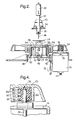
- a hollow stationery pillar or shaft 18 projects upwardly from the centre of the plate 14 and has a reflector platform 20 journalled thereon by means of a ball race 22.
- a metal lamp-mounting platform 24 is formed integrally with a pair of legs 26 that project downwardly through a hole 28 in the reflector platform 20 and are secured to the base plate 14 below the bottom of the shaft 18.
- a bulb holder 32 has a circular flange 34 which abuts against the top of the platform 24 and is held in place thereon by a clip having resilient lugs 36 that engage in respective windows 38 in each of the legs 26.
- the clip also has finger grips 40 which, when squeezed together, disengage the lugs 36 from the windows 38 and allow the bulb holder 34 to be removed.
- the bulb holder 34 supports a bulb 42 which is located at the focus of a parabolic or hyperbolic reflector 44 that is mounted on the rotary platform 20. The reflector 44 thus produces a generally horizontal beam of light which rotates with the platform 20.
- the flange 36 which serves as one terminal of the bulb holder 34, is in electrical connection with the platform 24.
- Each leg 26 has a blade terminal 46 on its bottom end. A first of the terminals 46 is connected to a first pole of an electrical power supply (not shown).
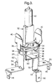
- the second terminal of the lamp holder 34 comprises a blade terminal 48 which projects downwardly from the bottom of the bulb holder. This is engaged by a U-shaped central portion 50 of a phosphor bronze strip 52. As can best be seen in Figure 3, the strip 52 also has L-shaped side limbs 54 and 56 which extend down the inside of the shaft 18 and have respective blade terminals 58 and 60 on their bottom ends 62 and 64, which are secured to the base plate 14 adjacent to the bottom of the shaft 18. The terminal 58 is connected to a second pole of the power supply.
- An electric motor 70 is mounted on the underside of the base plate 14 and has one of its electrical contacts in the form of a connector 72 engaging with the blade terminal 60. Its other electrical connector takes the form of a blade terminal 74 on its bottom end which is connected by a link (not shown) to the second of the terminals 46.
- the shaft 76 of the motor 70 projects upwardly through the base plate 14 and has a rubber pulley 78 mounted on its upper end.
- the pulley 78 comprises four cylindrical ribs 80, 82, 84 and 86 with annular grooves 88, 90 and 92 therebetween.
- the ribs 80-86 engage with a cylindrical flange 94 on the underside of the rotary platform 20.
- the flange 94 is spaced apart from the axis of the shaft 76 by less than the radius of the ribs 80-86 so that such ribs are compressed radially and bulge axially into the spaces 88-92, as illustrated. This maintains a satisfactory drive under a range of variations of the distance between the shaft 76 and the flange 94. Such differences can be due to manufacturing tolerances and also to changes of temperature.
- This pulley profile also provides relatively quiet running.
Landscapes
- Engineering & Computer Science (AREA)
- Mechanical Engineering (AREA)
- Non-Portable Lighting Devices Or Systems Thereof (AREA)
- Circuit Arrangement For Electric Light Sources In General (AREA)
- Road Signs Or Road Markings (AREA)
- Lighting Device Outwards From Vehicle And Optical Signal (AREA)
- Fastening Of Light Sources Or Lamp Holders (AREA)
- Electromechanical Clocks (AREA)
- Instrument Panels (AREA)
Abstract
Description
Claims (3)
- A warning lamp comprising a reflector (44) mounted on a rotary platform (20) which is journalled on a hollow pillar (18), and a light source (42) mounted on the pillar (18) and having a centre contact (48) engaging with a connector (52) within said pillar (18), the reflector (44) being arranged to direct light from said light source (42) in directions substantially perpendicular to the axis of rotation of said platform (20), characterised in that said connector comprises a spring (52) having a U-shaped portion (50) comprising two parallel limbs, and a support arm (54) extending from one of the limbs of the U-shaped portion (50) and having an end (62) secured to the pillar (18) so as to support the U-shaped portion (50) in a position in which its limbs grip said centre contact (48) of the light source (42).
- A warning lamp according to claim 1, wherein the support arm (54) is L-shaped with one limb extending from the U-shaped portion to an inner wall of said pillar (18) and another limb extending downwardly adjacent to said inner wall.
- A warning lamp according to claim 1 or 2, wherein the spring has two support arms (54, 56), each extending from a respective limb of the U-shaped portion (52).
Applications Claiming Priority (2)
| Application Number | Priority Date | Filing Date | Title |
|---|---|---|---|
| GB0127367 | 2001-11-15 | ||
| GB0127367A GB2382131B (en) | 2001-11-15 | 2001-11-15 | Warning lamp |
Publications (3)
| Publication Number | Publication Date |
|---|---|
| EP1312505A2 true EP1312505A2 (en) | 2003-05-21 |
| EP1312505A3 EP1312505A3 (en) | 2004-02-18 |
| EP1312505B1 EP1312505B1 (en) | 2007-01-24 |
Family
ID=9925790
Family Applications (1)
| Application Number | Title | Priority Date | Filing Date |
|---|---|---|---|
| EP02257684A Expired - Lifetime EP1312505B1 (en) | 2001-11-15 | 2002-11-06 | Warning lamp |
Country Status (5)
| Country | Link |
|---|---|
| EP (1) | EP1312505B1 (en) |
| AT (1) | ATE290967T1 (en) |
| DE (1) | DE60203237T2 (en) |
| ES (1) | ES2237652T3 (en) |
| GB (1) | GB2382131B (en) |
Cited By (1)
| Publication number | Priority date | Publication date | Assignee | Title |
|---|---|---|---|---|
| CN103453433A (en) * | 2012-05-28 | 2013-12-18 | 海洋王照明科技股份有限公司 | Alarming lamp |
Citations (1)
| Publication number | Priority date | Publication date | Assignee | Title |
|---|---|---|---|---|
| EP0879736A2 (en) | 1997-05-24 | 1998-11-25 | Britax PMG Limited | Warning lamp |
Family Cites Families (6)
| Publication number | Priority date | Publication date | Assignee | Title |
|---|---|---|---|---|
| EP0084923A1 (en) * | 1982-01-13 | 1983-08-03 | Britax PMG Limited | Signal lamps |
| GB8909825D0 (en) * | 1989-04-28 | 1989-06-14 | Lucas Ind Plc | Beacon lamps |
| DE3920763A1 (en) * | 1989-06-24 | 1991-01-03 | Hella Kg Hueck & Co | WARNING LIGHT FOR VEHICLES |
| DE4120754A1 (en) * | 1991-06-24 | 1993-01-14 | Hella Kg Hueck & Co | Warning light for use with motor vehicle - has rotating reflector in housing with centre bulb and socket removed in tilting action |
| US5517388A (en) * | 1995-01-26 | 1996-05-14 | Dominion Automotive Group, Inc. | Rotating light beacon including low-profile stepper motor |
| DE19831902C2 (en) * | 1998-07-16 | 2000-11-30 | Bosch Gmbh Robert | Rotating beacon |
-
2001
- 2001-11-15 GB GB0127367A patent/GB2382131B/en not_active Expired - Fee Related
-
2002
- 2002-11-06 DE DE60203237T patent/DE60203237T2/en not_active Expired - Lifetime
- 2002-11-06 ES ES02257683T patent/ES2237652T3/en not_active Expired - Lifetime
- 2002-11-06 AT AT02257683T patent/ATE290967T1/en not_active IP Right Cessation
- 2002-11-06 EP EP02257684A patent/EP1312505B1/en not_active Expired - Lifetime
Patent Citations (1)
| Publication number | Priority date | Publication date | Assignee | Title |
|---|---|---|---|---|
| EP0879736A2 (en) | 1997-05-24 | 1998-11-25 | Britax PMG Limited | Warning lamp |
Cited By (1)
| Publication number | Priority date | Publication date | Assignee | Title |
|---|---|---|---|---|
| CN103453433A (en) * | 2012-05-28 | 2013-12-18 | 海洋王照明科技股份有限公司 | Alarming lamp |
Also Published As
| Publication number | Publication date |
|---|---|
| ATE290967T1 (en) | 2005-04-15 |
| ES2237652T3 (en) | 2005-08-01 |
| GB0127367D0 (en) | 2002-01-09 |
| DE60203237D1 (en) | 2005-04-21 |
| GB2382131A (en) | 2003-05-21 |
| GB2382131B (en) | 2005-04-13 |
| EP1312505A3 (en) | 2004-02-18 |
| DE60203237T2 (en) | 2006-04-27 |
| EP1312505B1 (en) | 2007-01-24 |
Similar Documents
| Publication | Publication Date | Title |
|---|---|---|
| JP4662524B2 (en) | Headlamp lamp | |
| KR970003722B1 (en) | Flashlight with adjustable lamp housing | |
| US4769574A (en) | Incandescent lamp with a metal coupling to a plastic lamp base for automotive headlamp and like lighting applications | |
| CN107166339A (en) | A kind of light fixture fixed seat and light fitting connecting seat and a kind of lamp fixing device | |
| US10897113B1 (en) | Lamp cap and lamp holder thereof | |
| US5685638A (en) | Waterproof structure for a decorative light | |
| US1699927A (en) | Flash light | |
| US1933965A (en) | Trouble light | |
| EP1312505A2 (en) | Warning lamp | |
| EP0179524B1 (en) | Electrical lamp provided with a cap | |
| GB2382644A (en) | Warning lamp | |
| CN216793512U (en) | Push-button switch | |
| US6386732B1 (en) | Flashlight with a lamp base module mounted fixedly in a barrel thereof | |
| US3944808A (en) | Lamp mounting assembly | |
| CN1322532C (en) | Incandescent lamps and socket assemblies | |
| US2436259A (en) | Electric lamp base | |
| JP2000173321A (en) | Light bulb and lighting device provided with this light bulb | |
| US20060052010A1 (en) | Socket equipped with a centring ring for a wedge-base | |
| US5586904A (en) | Safety structure improvement of a bulb socket | |
| US1834318A (en) | Lighting fixture construction | |
| JPH0740445B2 (en) | lighting equipment | |
| GB2105531A (en) | Improvements relating to fittings for light bulbs | |
| US4055739A (en) | Lighted toggle lever switch | |
| US2821649A (en) | Electric lamp base | |
| GB2029093A (en) | Attachment of caps to press- sealed lamps |
Legal Events
| Date | Code | Title | Description |
|---|---|---|---|
| PUAI | Public reference made under article 153(3) epc to a published international application that has entered the european phase |
Free format text: ORIGINAL CODE: 0009012 |
|
| AK | Designated contracting states |
Designated state(s): AT BE BG CH CY CZ DE DK EE ES FI FR GB GR IE IT LI LU MC NL PT SE SK TR |
|
| AX | Request for extension of the european patent |
Extension state: AL LT LV MK RO SI |
|
| PUAL | Search report despatched |
Free format text: ORIGINAL CODE: 0009013 |
|
| AK | Designated contracting states |
Kind code of ref document: A3 Designated state(s): AT BE BG CH CY CZ DE DK EE ES FI FR GB GR IE IT LI LU MC NL PT SE SK TR |
|
| AX | Request for extension of the european patent |
Extension state: AL LT LV MK RO SI |
|
| 17P | Request for examination filed |
Effective date: 20040624 |
|
| R17P | Request for examination filed (corrected) |
Effective date: 20040621 |
|
| 17Q | First examination report despatched |
Effective date: 20040916 |
|
| AKX | Designation fees paid |
Designated state(s): AT BE BG CH CY CZ DE DK EE ES FI FR GB GR IE IT LI LU MC NL PT SE SK TR |
|
| GRAP | Despatch of communication of intention to grant a patent |
Free format text: ORIGINAL CODE: EPIDOSNIGR1 |
|
| GRAS | Grant fee paid |
Free format text: ORIGINAL CODE: EPIDOSNIGR3 |
|
| GRAA | (expected) grant |
Free format text: ORIGINAL CODE: 0009210 |
|
| AK | Designated contracting states |
Kind code of ref document: B1 Designated state(s): AT BE BG CH CY CZ DE DK EE ES FI FR GB GR IE IT LI LU MC NL PT SE SK TR |
|
| PG25 | Lapsed in a contracting state [announced via postgrant information from national office to epo] |
Ref country code: AT Free format text: LAPSE BECAUSE OF FAILURE TO SUBMIT A TRANSLATION OF THE DESCRIPTION OR TO PAY THE FEE WITHIN THE PRESCRIBED TIME-LIMIT Effective date: 20070124 Ref country code: LI Free format text: LAPSE BECAUSE OF FAILURE TO SUBMIT A TRANSLATION OF THE DESCRIPTION OR TO PAY THE FEE WITHIN THE PRESCRIBED TIME-LIMIT Effective date: 20070124 Ref country code: CH Free format text: LAPSE BECAUSE OF FAILURE TO SUBMIT A TRANSLATION OF THE DESCRIPTION OR TO PAY THE FEE WITHIN THE PRESCRIBED TIME-LIMIT Effective date: 20070124 Ref country code: DK Free format text: LAPSE BECAUSE OF FAILURE TO SUBMIT A TRANSLATION OF THE DESCRIPTION OR TO PAY THE FEE WITHIN THE PRESCRIBED TIME-LIMIT Effective date: 20070124 Ref country code: NL Free format text: LAPSE BECAUSE OF FAILURE TO SUBMIT A TRANSLATION OF THE DESCRIPTION OR TO PAY THE FEE WITHIN THE PRESCRIBED TIME-LIMIT Effective date: 20070124 Ref country code: FI Free format text: LAPSE BECAUSE OF FAILURE TO SUBMIT A TRANSLATION OF THE DESCRIPTION OR TO PAY THE FEE WITHIN THE PRESCRIBED TIME-LIMIT Effective date: 20070124 |
|
| REG | Reference to a national code |
Ref country code: GB Ref legal event code: FG4D |
|
| REG | Reference to a national code |
Ref country code: CH Ref legal event code: EP |
|
| REG | Reference to a national code |
Ref country code: IE Ref legal event code: FG4D |
|
| REF | Corresponds to: |
Ref document number: 60217798 Country of ref document: DE Date of ref document: 20070315 Kind code of ref document: P |
|
| PG25 | Lapsed in a contracting state [announced via postgrant information from national office to epo] |
Ref country code: SE Free format text: LAPSE BECAUSE OF FAILURE TO SUBMIT A TRANSLATION OF THE DESCRIPTION OR TO PAY THE FEE WITHIN THE PRESCRIBED TIME-LIMIT Effective date: 20070424 |
|
| PG25 | Lapsed in a contracting state [announced via postgrant information from national office to epo] |
Ref country code: BG Free format text: LAPSE BECAUSE OF THE APPLICANT RENOUNCES Effective date: 20070425 |
|
| PG25 | Lapsed in a contracting state [announced via postgrant information from national office to epo] |
Ref country code: ES Free format text: LAPSE BECAUSE OF FAILURE TO SUBMIT A TRANSLATION OF THE DESCRIPTION OR TO PAY THE FEE WITHIN THE PRESCRIBED TIME-LIMIT Effective date: 20070505 |
|
| PG25 | Lapsed in a contracting state [announced via postgrant information from national office to epo] |
Ref country code: PT Free format text: LAPSE BECAUSE OF FAILURE TO SUBMIT A TRANSLATION OF THE DESCRIPTION OR TO PAY THE FEE WITHIN THE PRESCRIBED TIME-LIMIT Effective date: 20070625 |
|
| REG | Reference to a national code |
Ref country code: CH Ref legal event code: PL |
|
| NLV1 | Nl: lapsed or annulled due to failure to fulfill the requirements of art. 29p and 29m of the patents act | ||
| ET | Fr: translation filed | ||
| PG25 | Lapsed in a contracting state [announced via postgrant information from national office to epo] |
Ref country code: SK Free format text: LAPSE BECAUSE OF FAILURE TO SUBMIT A TRANSLATION OF THE DESCRIPTION OR TO PAY THE FEE WITHIN THE PRESCRIBED TIME-LIMIT Effective date: 20070124 |
|
| PLBE | No opposition filed within time limit |
Free format text: ORIGINAL CODE: 0009261 |
|
| STAA | Information on the status of an ep patent application or granted ep patent |
Free format text: STATUS: NO OPPOSITION FILED WITHIN TIME LIMIT |
|
| BECA | Be: change of holder's address |
Owner name: BRITAX PMG LTD Effective date: 20070124 Owner name: BESSINGBY INDUSTRIAL ESTATE, BRIDLINGTON, EAST YOR Effective date: 20070124 |
|
| 26N | No opposition filed |
Effective date: 20071025 |
|
| PG25 | Lapsed in a contracting state [announced via postgrant information from national office to epo] |
Ref country code: CZ Free format text: LAPSE BECAUSE OF FAILURE TO SUBMIT A TRANSLATION OF THE DESCRIPTION OR TO PAY THE FEE WITHIN THE PRESCRIBED TIME-LIMIT Effective date: 20070124 |
|
| PG25 | Lapsed in a contracting state [announced via postgrant information from national office to epo] |
Ref country code: GR Free format text: LAPSE BECAUSE OF FAILURE TO SUBMIT A TRANSLATION OF THE DESCRIPTION OR TO PAY THE FEE WITHIN THE PRESCRIBED TIME-LIMIT Effective date: 20070425 |
|
| PG25 | Lapsed in a contracting state [announced via postgrant information from national office to epo] |
Ref country code: MC Free format text: LAPSE BECAUSE OF NON-PAYMENT OF DUE FEES Effective date: 20071130 |
|
| PG25 | Lapsed in a contracting state [announced via postgrant information from national office to epo] |
Ref country code: IE Free format text: LAPSE BECAUSE OF NON-PAYMENT OF DUE FEES Effective date: 20071106 |
|
| PG25 | Lapsed in a contracting state [announced via postgrant information from national office to epo] |
Ref country code: EE Free format text: LAPSE BECAUSE OF FAILURE TO SUBMIT A TRANSLATION OF THE DESCRIPTION OR TO PAY THE FEE WITHIN THE PRESCRIBED TIME-LIMIT Effective date: 20070124 |
|
| PG25 | Lapsed in a contracting state [announced via postgrant information from national office to epo] |
Ref country code: CY Free format text: LAPSE BECAUSE OF FAILURE TO SUBMIT A TRANSLATION OF THE DESCRIPTION OR TO PAY THE FEE WITHIN THE PRESCRIBED TIME-LIMIT Effective date: 20070124 |
|
| PG25 | Lapsed in a contracting state [announced via postgrant information from national office to epo] |
Ref country code: LU Free format text: LAPSE BECAUSE OF NON-PAYMENT OF DUE FEES Effective date: 20071106 |
|
| PG25 | Lapsed in a contracting state [announced via postgrant information from national office to epo] |
Ref country code: TR Free format text: LAPSE BECAUSE OF FAILURE TO SUBMIT A TRANSLATION OF THE DESCRIPTION OR TO PAY THE FEE WITHIN THE PRESCRIBED TIME-LIMIT Effective date: 20070124 |
|
| REG | Reference to a national code |
Ref country code: GB Ref legal event code: 732E Free format text: REGISTERED BETWEEN 20100715 AND 20100721 |
|
| REG | Reference to a national code |
Ref country code: DE Ref legal event code: R081 Ref document number: 60217798 Country of ref document: DE Owner name: BRITAX PMG LTD., LEEDS, GB Free format text: FORMER OWNER: BRITAX PMG LTD., GALLOWS HILL, WARWICK, GB Effective date: 20110518 |
|
| REG | Reference to a national code |
Ref country code: DE Ref legal event code: R082 Ref document number: 60217798 Country of ref document: DE Representative=s name: TBK, DE |
|
| REG | Reference to a national code |
Ref country code: DE Ref legal event code: R081 Ref document number: 60217798 Country of ref document: DE Owner name: BRITAX PMG LTD., GB Free format text: FORMER OWNER: BRITAX PMG LTD., LEEDS, GB Effective date: 20111005 Ref country code: DE Ref legal event code: R082 Ref document number: 60217798 Country of ref document: DE Representative=s name: TBK, DE Effective date: 20111005 Ref country code: DE Ref legal event code: R081 Ref document number: 60217798 Country of ref document: DE Owner name: BRITAX PMG LTD., LEEDS, GB Free format text: FORMER OWNER: BRITAX PMG LTD., LEEDS, WEST YORKSHIRE, GB Effective date: 20111005 |
|
| REG | Reference to a national code |
Ref country code: FR Ref legal event code: GC Effective date: 20120326 |
|
| PGFP | Annual fee paid to national office [announced via postgrant information from national office to epo] |
Ref country code: DE Payment date: 20131121 Year of fee payment: 12 Ref country code: GB Payment date: 20131129 Year of fee payment: 12 Ref country code: FR Payment date: 20131120 Year of fee payment: 12 |
|
| PGFP | Annual fee paid to national office [announced via postgrant information from national office to epo] |
Ref country code: IT Payment date: 20131128 Year of fee payment: 12 Ref country code: BE Payment date: 20131121 Year of fee payment: 12 |
|
| REG | Reference to a national code |
Ref country code: DE Ref legal event code: R119 Ref document number: 60217798 Country of ref document: DE |
|
| PG25 | Lapsed in a contracting state [announced via postgrant information from national office to epo] |
Ref country code: BE Free format text: LAPSE BECAUSE OF NON-PAYMENT OF DUE FEES Effective date: 20141130 |
|
| GBPC | Gb: european patent ceased through non-payment of renewal fee |
Effective date: 20141106 |
|
| REG | Reference to a national code |
Ref country code: FR Ref legal event code: ST Effective date: 20150731 |
|
| PG25 | Lapsed in a contracting state [announced via postgrant information from national office to epo] |
Ref country code: DE Free format text: LAPSE BECAUSE OF NON-PAYMENT OF DUE FEES Effective date: 20150602 Ref country code: GB Free format text: LAPSE BECAUSE OF NON-PAYMENT OF DUE FEES Effective date: 20141106 |
|
| PG25 | Lapsed in a contracting state [announced via postgrant information from national office to epo] |
Ref country code: FR Free format text: LAPSE BECAUSE OF NON-PAYMENT OF DUE FEES Effective date: 20141201 |
|
| PG25 | Lapsed in a contracting state [announced via postgrant information from national office to epo] |
Ref country code: IT Free format text: LAPSE BECAUSE OF NON-PAYMENT OF DUE FEES Effective date: 20141106 |