EP1312145B1 - Faceplate for an electrical switchboard - Google Patents
Faceplate for an electrical switchboard Download PDFInfo
- Publication number
- EP1312145B1 EP1312145B1 EP01969469.4A EP01969469A EP1312145B1 EP 1312145 B1 EP1312145 B1 EP 1312145B1 EP 01969469 A EP01969469 A EP 01969469A EP 1312145 B1 EP1312145 B1 EP 1312145B1
- Authority
- EP
- European Patent Office
- Prior art keywords
- faceplate
- opening
- hooks
- respect
- plate
- Prior art date
- Legal status (The legal status is an assumption and is not a legal conclusion. Google has not performed a legal analysis and makes no representation as to the accuracy of the status listed.)
- Expired - Lifetime
Links
- 230000008878 coupling Effects 0.000 claims description 15
- 238000010168 coupling process Methods 0.000 claims description 15
- 238000005859 coupling reaction Methods 0.000 claims description 15
- 238000004519 manufacturing process Methods 0.000 description 8
- 238000009434 installation Methods 0.000 description 4
- 230000008901 benefit Effects 0.000 description 3
- 238000010276 construction Methods 0.000 description 2
- 238000007689 inspection Methods 0.000 description 2
- 239000000463 material Substances 0.000 description 2
- 230000002159 abnormal effect Effects 0.000 description 1
- 230000015556 catabolic process Effects 0.000 description 1
- 238000005253 cladding Methods 0.000 description 1
- 230000002860 competitive effect Effects 0.000 description 1
- 238000006731 degradation reaction Methods 0.000 description 1
- 238000009826 distribution Methods 0.000 description 1
- 230000000694 effects Effects 0.000 description 1
- 238000009413 insulation Methods 0.000 description 1
- 239000007769 metal material Substances 0.000 description 1
- 238000000034 method Methods 0.000 description 1
- 238000012986 modification Methods 0.000 description 1
- 230000004048 modification Effects 0.000 description 1
- 238000012544 monitoring process Methods 0.000 description 1
- 230000001681 protective effect Effects 0.000 description 1
- 238000000926 separation method Methods 0.000 description 1
Images

Classifications
-
- H—ELECTRICITY
- H02—GENERATION; CONVERSION OR DISTRIBUTION OF ELECTRIC POWER
- H02B—BOARDS, SUBSTATIONS OR SWITCHING ARRANGEMENTS FOR THE SUPPLY OR DISTRIBUTION OF ELECTRIC POWER
- H02B1/00—Frameworks, boards, panels, desks, casings; Details of substations or switching arrangements
- H02B1/015—Boards, panels, desks; Parts thereof or accessories therefor
- H02B1/06—Boards, panels, desks; Parts thereof or accessories therefor having associated enclosures, e.g. for preventing access to live parts
Definitions
- the present invention relates to a faceplate for an electrical switchboard having improved functions and characteristics.
- These automatic circuit breakers are meant to provide the performance required to ensure the correct operation of the electric power supply circuit that they protect and of the loads connected thereto.
- they protect the loads against abnormal events caused for example by failures arising from short circuits or overloads by automatically opening said power supply circuit; they allow the correct connection/disconnection of loads to/from the electric power supply circuit; they ensure that the nominal current for the various connected users is actually equal to the required current; they allow, by way of a manual intervention on an actuation lever of said circuit breaker and the associated separation of the moving contacts from the fixed contacts, the complete insulation of a load with respect to a power supply source and the consequent disconnection of the circuit that they protect.
- the switchboards are provided with appropriate inspection doors which are functionally connected to the frame and are provided with suitable windows which allow to view and access the elements for controlling the circuit breakers and any other devices that are present.
- faceplates or escutcheons are fixed along the edges of the windows of the doors and are provided with openings which are suitable to accommodate the front part of a circuit breaker or of another device.
- the fixing of said faceplates requires additional work for providing, around the window, appropriate fixing holes which are suitable to accommodate screws or tangs for interlocking.
- said fixing is currently based on rigid couplings, it is a particularly critical aspect of the installation. Even slight inaccuracies can in fact entail degradation of one or all of the required functions; in such situations it is therefore necessary to resort to expensive manual interventions or even replace the entire door affected by the installation inaccuracy and reject it, with the consequent financial damage.
- Patent documents EP0620623 and US3278066 describe known examples of faceplates for electrical switchboards.
- the aim of the present invention is to provide a faceplate for an electrical switchboard which allows to obviate the drawbacks of the prior art and particularly allows to facilitate significantly the operations for coupling to the door of the switchboard and to the corresponding electrical device while ensuring the precision and functional effectiveness of said coupling.
- an object of the present invention is to provide a faceplate for an electrical switchboard which allows to reduce and simplify the process steps required for its execution and subsequent use, ensuring a high quality standard and eliminating the need for additional interventions for correcting its construction.
- Another object of the present invention is to provide a faceplate for an electrical switchboard which allows to eliminate or at least reduce significantly production rejects arising from inaccurate construction.
- Another object of the present invention is to provide a faceplate for an electrical switchboard which is highly reliable, relatively easy to manufacture and at competitive costs.
- the faceplate according to the invention allows to adjust its position with respect to the plate to which it is coupled directly during assembly; in this manner it is possible to compensate for any slacks with respect to the plate and the device without having to resort to complicated production steps, as regards both the faceplate and the plate, or to expensive and complicated corrective interventions after manufacture.
- the coupling between the faceplate and the plate is provided in an extremely simple and rapid manner, allowing to reduce installation times and costs.
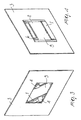
- the faceplate for an electrical switchboard comprises a substantially flat body 1 which, seen in plan view, is substantially quadrangular.
- the body 1 is rectangular; alternatively, according to the applications or to specific requirements, the shape of the body 1 can be modified appropriately so that it is for example square.
- an opening 2 which can accommodate at least part of an electrical and/or electronic device of the switchboard, in the manner described in detail hereinafter; as shown in Figure 1 , the opening 2 can have a rectangular shape or can be configured differently according to the geometric shape of the device or devices to which it is meant to be coupled.
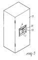
- Said devices can be constituted, for example, by an automatic circuit breaker 10, as shown in Figure 5 , or by buttons, PLC's (Programmable Logic Controllers), instruments for controlling and/or monitoring machines, et cetera.
- connection means which are suitable to facilitate its coupling to a plate 3 so that it can move with respect to said plate and their mutual position can be adjusted; as shown in Figures 3 and 4 , the plate 3, which is in practice a protective panel or an inspection door of the switchboard, has a window 5 which facilitates coupling to the faceplate in the manner described hereinafter.
- connection means provided on the body 1 comprise at least one hook 4 which is suitable to mate geometrically with one of the walls of the plate 3 that delimit the window 5; in particular, as shown in detail in Figure 2 , the hook 4 has a first base portion, which has a substantially curved lateral cross-section and protrudes from a wall 11 of the body 1 transversely to a reference plane on which the opening 2 lies, and a second portion, which is structurally continuous with respect to the first portion, has a variable thickness and is directed away from the opening 2 in the direction in which the wall 11 is arranged and at a certain distance from said wall.
- the second portion ends with a contoured head 8 which is suitable to increase the mechanical strength of the hook and facilitate guiding and coupling with the corresponding wall of the window 5.
- the hook 4 thus conceived has a flexible structure which allows to couple it easily to walls of plates or panels of different thickness.
- two flexible hooks 4 arranged on two walls 11 and 12 which are mutually opposite with respect to the opening 2; furthermore, the two hooks 4 are orientated in mutually opposite directions with respect to the opening 2 and are arranged along the corresponding walls 11 and 12 in a substantially centered position.
- This arrangement of the hooks 4 allows to move the faceplate with respect to the plate 3 along a first axis, which is orientated like the line that connects the two hooks 4, and along a second axis, which is perpendicular to the first one, in both directions.
- a protruding edge 7 is formed perimetrically along the edges of the opening 2, which protrudes transversely with respect to said opening 2 on the same side on which the hooks 4 are arranged, and is suitable to interact geometrically with the walls that delimit the window 5 and to facilitate centering between said window 5 and the opening 2.
- a pocket 6 is formed in one of the walls of the body 1, for example the wall 11, and on the opposite side with respect to the one where the hooks 4 are provided; said pocket is suitable to accommodate means, for example an indicator plate, for direct and immediate identification of the device 10 that is accommodated in the opening 2.
- the faceplate is coupled to the plate 3 by arranging it so that the hooks 4 are arranged diagonally with respect to the window 5, as shown in Figure 3 ; then the faceplate is turned, moving the hooks 4 so that they couple to the corresponding walls of the plate 3 and so that the opening 2 becomes aligned with the window 5.
- the assembly constituted by the plate and the faceplate is then moved into the final position, shown in Figure 5 , in which the circuit breaker 10 partially enters the opening 2.
- Said operation can be performed, for example, by turning the plate 3 about its pivoting axis on the frame of the switchboard, or on appropriate connection means which functionally connect the plate to said frame.
- a door 13 of the switchboard is closed so that a knob 14 of the circuit breaker protrudes from the plate 3 through the opening 2, allowing an operator to view it and, where necessary, intervene directly thereon.
- a movable mutual coupling is provided between the plate and the faceplate and allows, during assembly, to adjust the position of the faceplate with respect to the plate on a plane which is substantially parallel to the reference plane that contains said plate. Accordingly, this allows to obviate simply and effectively any constructive inaccuracies and any clearance between the plate and the faceplate and between the edges of the opening and the walls of the device, giving the assembly a pleasant aesthetic effect while ensuring the view of the device and direct access to its control elements.
- This provides the additional advantage of fully eliminating, or at least reducing significantly with respect to the prior art, production rejects and any corrective actions after production, and of simplifying said production steps.
- the great ease with which the faceplate couples to the plate allows to reduce installation times and costs, also thanks to the fact that the operations for providing holes in the panel and for subsequently fixing screws or tangs for engaging the faceplate are fully eliminated.
- the faceplate can be made of conventional plastic or metallic materials.
- the faceplate thus conceived is susceptible of numerous modifications and variations, all of which are within the scope of the inventive concept; for example, depending on the applications, the dimensions of the faceplate and of one electrical and/or electronic device of the switchboard. All the details may furthermore be replaced with technically equivalent elements.
- the materials used so long as they are compatible with the specific use, as well as the shapes and the dimensions, may be any according to requirements and the state of the art, the scope of the invention being defined in claim 1.
Landscapes
- Engineering & Computer Science (AREA)
- Power Engineering (AREA)
- Patch Boards (AREA)
- Distribution Board (AREA)
- Display Devices Of Pinball Game Machines (AREA)
Description
- The present invention relates to a faceplate for an electrical switchboard having improved functions and characteristics.
- It is known that low-voltage industrial electrical systems which handle high-level currents, and therefore high power levels, usually use specific devices which are commonly known in the art as automatic power circuit breakers.
- These automatic circuit breakers are meant to provide the performance required to ensure the correct operation of the electric power supply circuit that they protect and of the loads connected thereto. In particular, they protect the loads against abnormal events caused for example by failures arising from short circuits or overloads by automatically opening said power supply circuit; they allow the correct connection/disconnection of loads to/from the electric power supply circuit; they ensure that the nominal current for the various connected users is actually equal to the required current; they allow, by way of a manual intervention on an actuation lever of said circuit breaker and the associated separation of the moving contacts from the fixed contacts, the complete insulation of a load with respect to a power supply source and the consequent disconnection of the circuit that they protect.
- In practical use in electrical systems, automatic circuit breakers are generally used by arranging them in appropriately provided electrical switchboards, typically electrical distribution switchboards. These switchboards, according to solutions which are widely known in the art, use a supporting frame which bounds a volume in which the circuit breakers and any other electrical and/or electronic devices of the switchboard are placed; furthermore, said frame constitutes a skeleton which is suitable to structurally support the various components of the switchboard that are functionally connected thereto, such as guides or supporting plates on which the circuit breakers and the various devices are arranged, cladding plates, doors for opening/closing said switchboards, et cetera.
- In particular, the switchboards are provided with appropriate inspection doors which are functionally connected to the frame and are provided with suitable windows which allow to view and access the elements for controlling the circuit breakers and any other devices that are present.
- In the current state of the art, the solutions used to provide the doors and the modes for coupling to the devices have some drawbacks. In order to ensure correct coupling between the devices and the door, adequate functionality of the parts, safety and practicality in use, as well as a pleasant aesthetic appearance of the assembly, the doors require blanking operations with highly precise carpentry work; essentially, they require complicated and expensive production processes.
- In order to obviate these drawbacks at least partially, faceplates or escutcheons are fixed along the edges of the windows of the doors and are provided with openings which are suitable to accommodate the front part of a circuit breaker or of another device. The fixing of said faceplates, however, requires additional work for providing, around the window, appropriate fixing holes which are suitable to accommodate screws or tangs for interlocking. Furthermore, since said fixing is currently based on rigid couplings, it is a particularly critical aspect of the installation. Even slight inaccuracies can in fact entail degradation of one or all of the required functions; in such situations it is therefore necessary to resort to expensive manual interventions or even replace the entire door affected by the installation inaccuracy and reject it, with the consequent financial damage.
-
- The aim of the present invention is to provide a faceplate for an electrical switchboard which allows to obviate the drawbacks of the prior art and particularly allows to facilitate significantly the operations for coupling to the door of the switchboard and to the corresponding electrical device while ensuring the precision and functional effectiveness of said coupling.
- Within this aim, an object of the present invention is to provide a faceplate for an electrical switchboard which allows to reduce and simplify the process steps required for its execution and subsequent use, ensuring a high quality standard and eliminating the need for additional interventions for correcting its construction.
- Another object of the present invention is to provide a faceplate for an electrical switchboard which allows to eliminate or at least reduce significantly production rejects arising from inaccurate construction.
- Another object of the present invention is to provide a faceplate for an electrical switchboard which is highly reliable, relatively easy to manufacture and at competitive costs.
- This aim and these and other objects which will become better apparent hereinafter are achieved by a faceplate for an electrical switchboard, according to the following claim 1.
- Advantageously, the faceplate according to the invention allows to adjust its position with respect to the plate to which it is coupled directly during assembly; in this manner it is possible to compensate for any slacks with respect to the plate and the device without having to resort to complicated production steps, as regards both the faceplate and the plate, or to expensive and complicated corrective interventions after manufacture. Furthermore, the coupling between the faceplate and the plate is provided in an extremely simple and rapid manner, allowing to reduce installation times and costs.
- Further characteristics and advantages of the present invention will become better apparent from the description of some preferred but not exclusive embodiments of a faceplate for an electrical switchboard according to the invention, illustrated only by way of non-limitative example in the accompanying drawings, wherein:
-
Figures 1a and 1b are perspective views of, respectively, the rear and front parts of a faceplate for an electrical switchboard according to the invention; -
Figure 2 is a perspective view of a detail of the coupling means formed in the faceplate ofFigure 1 ; -
Figure 3 is a perspective view of a faceplate according to the invention during coupling to a plate of an electrical switchboard; -
Figure 4 is a perspective view of the faceplate according to the invention, coupled to a plate of an electrical switchboard; -
Figure 5 is a perspective view of an electrical switchboard with a faceplate according to the invention, coupled to an automatic circuit breaker. - With reference to the above cited figures, the faceplate for an electrical switchboard according to the invention comprises a substantially flat body 1 which, seen in plan view, is substantially quadrangular. In particular, in the embodiment shown in
Figure 1 , the body 1 is rectangular; alternatively, according to the applications or to specific requirements, the shape of the body 1 can be modified appropriately so that it is for example square. - In the body 1, in a substantially centered position, there is provided an
opening 2 which can accommodate at least part of an electrical and/or electronic device of the switchboard, in the manner described in detail hereinafter; as shown inFigure 1 , theopening 2 can have a rectangular shape or can be configured differently according to the geometric shape of the device or devices to which it is meant to be coupled. Said devices can be constituted, for example, by anautomatic circuit breaker 10, as shown inFigure 5 , or by buttons, PLC's (Programmable Logic Controllers), instruments for controlling and/or monitoring machines, et cetera. - Advantageously, on the body 1 of the faceplate there are provided connection means which are suitable to facilitate its coupling to a
plate 3 so that it can move with respect to said plate and their mutual position can be adjusted; as shown inFigures 3 and 4 , theplate 3, which is in practice a protective panel or an inspection door of the switchboard, has awindow 5 which facilitates coupling to the faceplate in the manner described hereinafter. - The connection means provided on the body 1 comprise at least one hook 4 which is suitable to mate geometrically with one of the walls of the
plate 3 that delimit thewindow 5; in particular, as shown in detail inFigure 2 , the hook 4 has a first base portion, which has a substantially curved lateral cross-section and protrudes from awall 11 of the body 1 transversely to a reference plane on which the opening 2 lies, and a second portion, which is structurally continuous with respect to the first portion, has a variable thickness and is directed away from theopening 2 in the direction in which thewall 11 is arranged and at a certain distance from said wall. Finally, the second portion ends with a contouredhead 8 which is suitable to increase the mechanical strength of the hook and facilitate guiding and coupling with the corresponding wall of thewindow 5. Advantageously, the hook 4 thus conceived has a flexible structure which allows to couple it easily to walls of plates or panels of different thickness. - In a preferred embodiment of the faceplate according to the invention, and as shown in detail in
Figures 1 and3 , on the body 1 there are provided two flexible hooks 4 arranged on twowalls opening 2; furthermore, the two hooks 4 are orientated in mutually opposite directions with respect to theopening 2 and are arranged along thecorresponding walls plate 3 along a first axis, which is orientated like the line that connects the two hooks 4, and along a second axis, which is perpendicular to the first one, in both directions. - Furthermore, a
protruding edge 7 is formed perimetrically along the edges of theopening 2, which protrudes transversely with respect to said opening 2 on the same side on which the hooks 4 are arranged, and is suitable to interact geometrically with the walls that delimit thewindow 5 and to facilitate centering between saidwindow 5 and theopening 2. - Finally, a pocket 6 is formed in one of the walls of the body 1, for example the
wall 11, and on the opposite side with respect to the one where the hooks 4 are provided; said pocket is suitable to accommodate means, for example an indicator plate, for direct and immediate identification of thedevice 10 that is accommodated in theopening 2. - In practice, during assembly the faceplate is coupled to the
plate 3 by arranging it so that the hooks 4 are arranged diagonally with respect to thewindow 5, as shown inFigure 3 ; then the faceplate is turned, moving the hooks 4 so that they couple to the corresponding walls of theplate 3 and so that theopening 2 becomes aligned with thewindow 5. The assembly constituted by the plate and the faceplate is then moved into the final position, shown inFigure 5 , in which thecircuit breaker 10 partially enters theopening 2. Said operation can be performed, for example, by turning theplate 3 about its pivoting axis on the frame of the switchboard, or on appropriate connection means which functionally connect the plate to said frame. Finally, adoor 13 of the switchboard is closed so that aknob 14 of the circuit breaker protrudes from theplate 3 through theopening 2, allowing an operator to view it and, where necessary, intervene directly thereon. - In practice it has been found that the frame for electrical switchboard according to the invention fully achieves the intended aim and objects, allowing a significant series of advantages with respect to the known art.
- In particular, thanks to the presence of the pair of hooks, a movable mutual coupling is provided between the plate and the faceplate and allows, during assembly, to adjust the position of the faceplate with respect to the plate on a plane which is substantially parallel to the reference plane that contains said plate. Accordingly, this allows to obviate simply and effectively any constructive inaccuracies and any clearance between the plate and the faceplate and between the edges of the opening and the walls of the device, giving the assembly a pleasant aesthetic effect while ensuring the view of the device and direct access to its control elements. This provides the additional advantage of fully eliminating, or at least reducing significantly with respect to the prior art, production rejects and any corrective actions after production, and of simplifying said production steps.
- In addition to this, the great ease with which the faceplate couples to the plate allows to reduce installation times and costs, also thanks to the fact that the operations for providing holes in the panel and for subsequently fixing screws or tangs for engaging the faceplate are fully eliminated.
- The fact should not be ignored that all the innovative functions and inventive aspects of the faceplate can be obtained by using commonly commercially available elements and materials with extremely modest costs and according to a solution which is constructively simple and functionally effective; for example, the faceplate can be made of conventional plastic or metallic materials.
- The faceplate thus conceived is susceptible of numerous modifications and variations, all of which are within the scope of the inventive concept; for example, depending on the applications, the dimensions of the faceplate and of one electrical and/or electronic device of the switchboard. All the details may furthermore be replaced with technically equivalent elements. In practice, the materials used, so long as they are compatible with the specific use, as well as the shapes and the dimensions, may be any according to requirements and the state of the art, the scope of the invention being defined in claim 1.
Claims (8)
- A faceplate for an electrical switchboard, comprising a body (1) which has a substantially quadrangular shape and is provided with an opening (2) to accommodate at least part of an electrical and/or electronic device of the switchboard, said faceplate being suitable to be operatively coupled to a window (5) provided on a plate (3), said body having connection means for coupling to the plate, at the edges of said window, in a movable and adjustable manner with respect to the plate itself, said connection means being suitable to allow coupling to the plate in a position which is adjustable on a plane substantially parallel to a reference plane on which said plate lies characterized in that said connection means comprise two hooks (4) protruding from a wall (11) of said body (1), transversely to a reference plane on which said opening (2) lies, said hooks (4) being arranged on said body (1) on mutually opposite sides with respect to said opening (2) and being orientated in opposite directions.
- The faceplate for electrical switchboard according to claim 1, characterized in that said hooks (4) comprise a first portion, which has a substantially curved lateral cross-section and protrudes from an edge of said opening (2), and a second portion, which is structurally continuous with respect to the first portion, lies parallel to the extension of the wall (11), is spaced from it and is directed away from said opening (2).
- The faceplate for electrical switchboard according to claim 2, characterized in that said second portion ends with a contoured head which is suitable to mechanically stiffen said hooks (4) and facilitate its coupling to a corresponding edge of the window (5).
- The faceplate for electrical switchboard according to one or more of preceding claims, characterized in that said hooks (4) are flexible.
- The faceplate for electrical switchboard according to one or more of preceding claims, characterized in that said hooks (4) are arranged on two opposite walls (11, 12) of said body (1) in a position which is centered with respect to said opening (2).
- The faceplate for electrical switchboard according to one or more of the preceding claims, characterized in that a pocket (6) is formed in a wall of said body, on the opposite side with respect to the one from which said hooks (4) protrude, said pocket (6) being suitable to accommodate means for identifying the device (10) that can be accommodated in said opening (2).
- The faceplate for electrical switchboard according to one or more of the preceding claims, characterized in that along the edges of said opening (2) a protruding edge (7) is formed which protrudes transversely to it, said protruding edge (7) being suitable to interact geometrically with the walls of said window (5) and to facilitate its centering with respect to said opening (2).
- An electrical switchboard, characterized in that it comprises a faceplate according to one or more of the preceding claims.
Applications Claiming Priority (3)
| Application Number | Priority Date | Filing Date | Title |
|---|---|---|---|
| ITMI001687 | 2000-07-24 | ||
| IT2000MI001687A IT1318234B1 (en) | 2000-07-24 | 2000-07-24 | FRAME FOR ELECTRICAL PANEL |
| PCT/EP2001/008463 WO2002009248A1 (en) | 2000-07-24 | 2001-07-20 | Faceplate for an electrical switchboard |
Publications (2)
| Publication Number | Publication Date |
|---|---|
| EP1312145A1 EP1312145A1 (en) | 2003-05-21 |
| EP1312145B1 true EP1312145B1 (en) | 2014-10-08 |
Family
ID=11445549
Family Applications (1)
| Application Number | Title | Priority Date | Filing Date |
|---|---|---|---|
| EP01969469.4A Expired - Lifetime EP1312145B1 (en) | 2000-07-24 | 2001-07-20 | Faceplate for an electrical switchboard |
Country Status (8)
| Country | Link |
|---|---|
| US (1) | US6858803B2 (en) |
| EP (1) | EP1312145B1 (en) |
| CN (1) | CN1265523C (en) |
| AU (1) | AU2001289721A1 (en) |
| EG (1) | EG24458A (en) |
| ES (1) | ES2526611T3 (en) |
| IT (1) | IT1318234B1 (en) |
| WO (1) | WO2002009248A1 (en) |
Families Citing this family (2)
| Publication number | Priority date | Publication date | Assignee | Title |
|---|---|---|---|---|
| FR2846158B1 (en) * | 2002-10-22 | 2004-12-24 | Schneider Electric Ind Sas | CHASSIS FOR ELECTRICAL EQUIPMENT |
| DE102010041724A1 (en) * | 2010-09-30 | 2012-04-05 | Siemens Aktiengesellschaft | frame |
Family Cites Families (4)
| Publication number | Priority date | Publication date | Assignee | Title |
|---|---|---|---|---|
| US3278066A (en) | 1965-05-12 | 1966-10-11 | Square D Co | Closure plate for electrical panelboard |
| DE3302530C2 (en) * | 1983-01-26 | 1985-09-26 | ABL Bayerische Elektrozubehör GmbH & Co KG, 8560 Lauf | Blind cover strips for distributors |
| US4737599A (en) * | 1986-10-02 | 1988-04-12 | Serge Fontaine | Electric outlet safety cover |
| FR2704106B1 (en) | 1993-04-16 | 1995-06-02 | Merlin Gerin | Cover for opening an electrical cabinet. |
-
2000
- 2000-07-24 IT IT2000MI001687A patent/IT1318234B1/en active
-
2001
- 2001-07-20 US US10/333,788 patent/US6858803B2/en not_active Expired - Fee Related
- 2001-07-20 AU AU2001289721A patent/AU2001289721A1/en not_active Abandoned
- 2001-07-20 WO PCT/EP2001/008463 patent/WO2002009248A1/en not_active Ceased
- 2001-07-20 EP EP01969469.4A patent/EP1312145B1/en not_active Expired - Lifetime
- 2001-07-20 CN CNB018132324A patent/CN1265523C/en not_active Expired - Lifetime
- 2001-07-20 ES ES01969469.4T patent/ES2526611T3/en not_active Expired - Lifetime
- 2001-07-21 EG EG20010800A patent/EG24458A/en active
Also Published As
| Publication number | Publication date |
|---|---|
| AU2001289721A1 (en) | 2002-02-05 |
| EG24458A (en) | 2009-07-16 |
| US6858803B2 (en) | 2005-02-22 |
| CN1265523C (en) | 2006-07-19 |
| US20030150636A1 (en) | 2003-08-14 |
| ITMI20001687A1 (en) | 2002-01-24 |
| WO2002009248A1 (en) | 2002-01-31 |
| IT1318234B1 (en) | 2003-07-28 |
| CN1443387A (en) | 2003-09-17 |
| ES2526611T3 (en) | 2015-01-13 |
| ITMI20001687A0 (en) | 2000-07-24 |
| EP1312145A1 (en) | 2003-05-21 |
Similar Documents
| Publication | Publication Date | Title |
|---|---|---|
| EP3703095B1 (en) | Fixing and unlocking mechanism for plug-in type circuit breaker | |
| EP1356484B1 (en) | Interlocking device for circuit breakers | |
| US4668035A (en) | Distribution system and column for electric switching apparatus | |
| US6858803B2 (en) | Faceplate for an electrical switchboard | |
| US20020130023A1 (en) | Methods and apparatus for automatically transferring electrical power | |
| US6547348B2 (en) | Interlocking trim plates | |
| EP1164672B1 (en) | Cabinet for electrical switchboard | |
| EP2352619B1 (en) | A method of manufacturing a switchgear panel | |
| KR20120001883U (en) | Rated current setting mechanism for overcurrent relay in circuit breaker | |
| JP2010061830A (en) | Electric operating device of circuit breaker | |
| EP2571121B1 (en) | Withdrawable unit with rotating electrical contacts | |
| JPH0134482Y2 (en) | ||
| EP1139532B1 (en) | Switchboard and frame member | |
| CN213752437U (en) | Double-circuit power supply mechanical interlocking device for miniature circuit breaker | |
| CN220272399U (en) | Plastic case switch installation positioning device | |
| JP4291036B2 (en) | Circuit breakers and distribution boards | |
| EP1143588B1 (en) | Upright for electric board | |
| CN220139894U (en) | Control cabinet convenient to adjust and install | |
| JP2002305811A (en) | Connection changer and distribution board using the same | |
| EP1570556B1 (en) | Withdrawable unit for switchgear | |
| CN215869219U (en) | Multi-pole circuit breaker | |
| CN220985127U (en) | Device for preventing mistaken touch of opening and closing contactor | |
| CN211126648U (en) | Dual supply block terminal isolation structure | |
| CN210296926U (en) | Control cabinet for pipe bending machine | |
| CN213150689U (en) | Low-voltage frame type circuit breaker |
Legal Events
| Date | Code | Title | Description |
|---|---|---|---|
| PUAI | Public reference made under article 153(3) epc to a published international application that has entered the european phase |
Free format text: ORIGINAL CODE: 0009012 |
|
| 17P | Request for examination filed |
Effective date: 20030220 |
|
| AK | Designated contracting states |
Designated state(s): AT BE CH CY DE DK ES FI FR GB GR IE IT LI LU MC NL PT SE TR |
|
| AX | Request for extension of the european patent |
Extension state: AL LT LV MK RO SI |
|
| RAP1 | Party data changed (applicant data changed or rights of an application transferred) |
Owner name: ABB SERVICE S.R.L |
|
| RAP1 | Party data changed (applicant data changed or rights of an application transferred) |
Owner name: ABB S.P.A. |
|
| 17Q | First examination report despatched |
Effective date: 20091026 |
|
| GRAP | Despatch of communication of intention to grant a patent |
Free format text: ORIGINAL CODE: EPIDOSNIGR1 |
|
| INTG | Intention to grant announced |
Effective date: 20140502 |
|
| GRAS | Grant fee paid |
Free format text: ORIGINAL CODE: EPIDOSNIGR3 |
|
| GRAA | (expected) grant |
Free format text: ORIGINAL CODE: 0009210 |
|
| AK | Designated contracting states |
Kind code of ref document: B1 Designated state(s): AT BE CH CY DE DK ES FI FR GB GR IE IT LI LU MC NL PT SE TR |
|
| REG | Reference to a national code |
Ref country code: GB Ref legal event code: FG4D |
|
| REG | Reference to a national code |
Ref country code: AT Ref legal event code: REF Ref document number: 691074 Country of ref document: AT Kind code of ref document: T Effective date: 20141015 Ref country code: CH Ref legal event code: EP |
|
| REG | Reference to a national code |
Ref country code: IE Ref legal event code: FG4D |
|
| REG | Reference to a national code |
Ref country code: DE Ref legal event code: R096 Ref document number: 60149044 Country of ref document: DE Effective date: 20141120 |
|
| REG | Reference to a national code |
Ref country code: ES Ref legal event code: FG2A Ref document number: 2526611 Country of ref document: ES Kind code of ref document: T3 Effective date: 20150113 |
|
| REG | Reference to a national code |
Ref country code: NL Ref legal event code: T3 |
|
| REG | Reference to a national code |
Ref country code: AT Ref legal event code: MK05 Ref document number: 691074 Country of ref document: AT Kind code of ref document: T Effective date: 20141008 |
|
| PG25 | Lapsed in a contracting state [announced via postgrant information from national office to epo] |
Ref country code: FI Free format text: LAPSE BECAUSE OF FAILURE TO SUBMIT A TRANSLATION OF THE DESCRIPTION OR TO PAY THE FEE WITHIN THE PRESCRIBED TIME-LIMIT Effective date: 20141008 Ref country code: PT Free format text: LAPSE BECAUSE OF FAILURE TO SUBMIT A TRANSLATION OF THE DESCRIPTION OR TO PAY THE FEE WITHIN THE PRESCRIBED TIME-LIMIT Effective date: 20150209 |
|
| PG25 | Lapsed in a contracting state [announced via postgrant information from national office to epo] |
Ref country code: CY Free format text: LAPSE BECAUSE OF FAILURE TO SUBMIT A TRANSLATION OF THE DESCRIPTION OR TO PAY THE FEE WITHIN THE PRESCRIBED TIME-LIMIT Effective date: 20141008 Ref country code: SE Free format text: LAPSE BECAUSE OF FAILURE TO SUBMIT A TRANSLATION OF THE DESCRIPTION OR TO PAY THE FEE WITHIN THE PRESCRIBED TIME-LIMIT Effective date: 20141008 Ref country code: AT Free format text: LAPSE BECAUSE OF FAILURE TO SUBMIT A TRANSLATION OF THE DESCRIPTION OR TO PAY THE FEE WITHIN THE PRESCRIBED TIME-LIMIT Effective date: 20141008 Ref country code: GR Free format text: LAPSE BECAUSE OF FAILURE TO SUBMIT A TRANSLATION OF THE DESCRIPTION OR TO PAY THE FEE WITHIN THE PRESCRIBED TIME-LIMIT Effective date: 20150109 |
|
| REG | Reference to a national code |
Ref country code: DE Ref legal event code: R097 Ref document number: 60149044 Country of ref document: DE |
|
| PG25 | Lapsed in a contracting state [announced via postgrant information from national office to epo] |
Ref country code: DK Free format text: LAPSE BECAUSE OF FAILURE TO SUBMIT A TRANSLATION OF THE DESCRIPTION OR TO PAY THE FEE WITHIN THE PRESCRIBED TIME-LIMIT Effective date: 20141008 |
|
| PLBE | No opposition filed within time limit |
Free format text: ORIGINAL CODE: 0009261 |
|
| STAA | Information on the status of an ep patent application or granted ep patent |
Free format text: STATUS: NO OPPOSITION FILED WITHIN TIME LIMIT |
|
| 26N | No opposition filed |
Effective date: 20150709 |
|
| PGFP | Annual fee paid to national office [announced via postgrant information from national office to epo] |
Ref country code: NL Payment date: 20150721 Year of fee payment: 15 |
|
| PG25 | Lapsed in a contracting state [announced via postgrant information from national office to epo] |
Ref country code: MC Free format text: LAPSE BECAUSE OF FAILURE TO SUBMIT A TRANSLATION OF THE DESCRIPTION OR TO PAY THE FEE WITHIN THE PRESCRIBED TIME-LIMIT Effective date: 20141008 |
|
| REG | Reference to a national code |
Ref country code: CH Ref legal event code: PL |
|
| PG25 | Lapsed in a contracting state [announced via postgrant information from national office to epo] |
Ref country code: LU Free format text: LAPSE BECAUSE OF FAILURE TO SUBMIT A TRANSLATION OF THE DESCRIPTION OR TO PAY THE FEE WITHIN THE PRESCRIBED TIME-LIMIT Effective date: 20150720 |
|
| REG | Reference to a national code |
Ref country code: IE Ref legal event code: MM4A |
|
| PG25 | Lapsed in a contracting state [announced via postgrant information from national office to epo] |
Ref country code: LI Free format text: LAPSE BECAUSE OF NON-PAYMENT OF DUE FEES Effective date: 20150731 Ref country code: CH Free format text: LAPSE BECAUSE OF NON-PAYMENT OF DUE FEES Effective date: 20150731 |
|
| REG | Reference to a national code |
Ref country code: FR Ref legal event code: PLFP Year of fee payment: 16 |
|
| PG25 | Lapsed in a contracting state [announced via postgrant information from national office to epo] |
Ref country code: IE Free format text: LAPSE BECAUSE OF NON-PAYMENT OF DUE FEES Effective date: 20150720 |
|
| REG | Reference to a national code |
Ref country code: NL Ref legal event code: MM Effective date: 20160801 |
|
| PG25 | Lapsed in a contracting state [announced via postgrant information from national office to epo] |
Ref country code: NL Free format text: LAPSE BECAUSE OF NON-PAYMENT OF DUE FEES Effective date: 20160801 |
|
| REG | Reference to a national code |
Ref country code: FR Ref legal event code: PLFP Year of fee payment: 17 |
|
| PG25 | Lapsed in a contracting state [announced via postgrant information from national office to epo] |
Ref country code: BE Free format text: LAPSE BECAUSE OF FAILURE TO SUBMIT A TRANSLATION OF THE DESCRIPTION OR TO PAY THE FEE WITHIN THE PRESCRIBED TIME-LIMIT Effective date: 20141008 |
|
| REG | Reference to a national code |
Ref country code: FR Ref legal event code: PLFP Year of fee payment: 18 |
|
| PGFP | Annual fee paid to national office [announced via postgrant information from national office to epo] |
Ref country code: TR Payment date: 20200720 Year of fee payment: 20 Ref country code: DE Payment date: 20200721 Year of fee payment: 20 Ref country code: ES Payment date: 20200922 Year of fee payment: 20 Ref country code: GB Payment date: 20200727 Year of fee payment: 20 Ref country code: FR Payment date: 20200721 Year of fee payment: 20 |
|
| PGFP | Annual fee paid to national office [announced via postgrant information from national office to epo] |
Ref country code: IT Payment date: 20200724 Year of fee payment: 20 |
|
| REG | Reference to a national code |
Ref country code: DE Ref legal event code: R071 Ref document number: 60149044 Country of ref document: DE |
|
| REG | Reference to a national code |
Ref country code: GB Ref legal event code: PE20 Expiry date: 20210719 |
|
| REG | Reference to a national code |
Ref country code: ES Ref legal event code: FD2A Effective date: 20211027 |
|
| PG25 | Lapsed in a contracting state [announced via postgrant information from national office to epo] |
Ref country code: GB Free format text: LAPSE BECAUSE OF EXPIRATION OF PROTECTION Effective date: 20210719 |
|
| PG25 | Lapsed in a contracting state [announced via postgrant information from national office to epo] |
Ref country code: ES Free format text: LAPSE BECAUSE OF EXPIRATION OF PROTECTION Effective date: 20210721 |