EP1311596B1 - Method and apparatus for manufacturing phenolic foams by impingement mixing - Google Patents
Method and apparatus for manufacturing phenolic foams by impingement mixing Download PDFInfo
- Publication number
- EP1311596B1 EP1311596B1 EP01984331A EP01984331A EP1311596B1 EP 1311596 B1 EP1311596 B1 EP 1311596B1 EP 01984331 A EP01984331 A EP 01984331A EP 01984331 A EP01984331 A EP 01984331A EP 1311596 B1 EP1311596 B1 EP 1311596B1
- Authority
- EP
- European Patent Office
- Prior art keywords
- stream
- low pressure
- phenolic
- bar
- pressure
- Prior art date
- Legal status (The legal status is an assumption and is not a legal conclusion. Google has not performed a legal analysis and makes no representation as to the accuracy of the status listed.)
- Expired - Lifetime
Links
- 239000006260 foam Substances 0.000 title claims abstract description 44
- ISWSIDIOOBJBQZ-UHFFFAOYSA-N phenol group Chemical group C1(=CC=CC=C1)O ISWSIDIOOBJBQZ-UHFFFAOYSA-N 0.000 title claims abstract description 40
- 238000000034 method Methods 0.000 title claims description 42
- 238000004519 manufacturing process Methods 0.000 title claims description 13
- 239000000376 reactant Substances 0.000 claims abstract description 45
- KXGFMDJXCMQABM-UHFFFAOYSA-N 2-methoxy-6-methylphenol Chemical compound [CH]OC1=CC=CC([CH])=C1O KXGFMDJXCMQABM-UHFFFAOYSA-N 0.000 claims abstract description 40
- 239000005011 phenolic resin Substances 0.000 claims abstract description 40
- 229920001568 phenolic resin Polymers 0.000 claims abstract description 40
- 239000002253 acid Substances 0.000 claims abstract description 23
- 239000000203 mixture Substances 0.000 claims abstract description 23
- 239000000758 substrate Substances 0.000 claims description 41
- 239000007788 liquid Substances 0.000 claims description 20
- 239000004604 Blowing Agent Substances 0.000 claims description 10
- 238000010438 heat treatment Methods 0.000 claims description 6
- 239000008258 liquid foam Substances 0.000 claims description 3
- 229910052751 metal Inorganic materials 0.000 claims description 3
- 239000002184 metal Substances 0.000 claims description 3
- 239000002131 composite material Substances 0.000 abstract description 2
- 229920005989 resin Polymers 0.000 description 14
- 239000011347 resin Substances 0.000 description 14
- 230000000704 physical effect Effects 0.000 description 3
- 238000005273 aeration Methods 0.000 description 2
- 229910052782 aluminium Inorganic materials 0.000 description 2
- XAGFODPZIPBFFR-UHFFFAOYSA-N aluminium Chemical compound [Al] XAGFODPZIPBFFR-UHFFFAOYSA-N 0.000 description 2
- 239000000839 emulsion Substances 0.000 description 2
- 238000005187 foaming Methods 0.000 description 2
- 239000011888 foil Substances 0.000 description 2
- 239000000126 substance Substances 0.000 description 2
- 241000408529 Libra Species 0.000 description 1
- QAOWNCQODCNURD-UHFFFAOYSA-N Sulfuric acid Chemical compound OS(O)(=O)=O QAOWNCQODCNURD-UHFFFAOYSA-N 0.000 description 1
- 238000011161 development Methods 0.000 description 1
- 230000018109 developmental process Effects 0.000 description 1
- 238000002347 injection Methods 0.000 description 1
- 239000007924 injection Substances 0.000 description 1
- 239000011810 insulating material Substances 0.000 description 1
- 238000005461 lubrication Methods 0.000 description 1
- OQUKIQWCVTZJAF-UHFFFAOYSA-N phenol;sulfuric acid Chemical compound OS(O)(=O)=O.OC1=CC=CC=C1 OQUKIQWCVTZJAF-UHFFFAOYSA-N 0.000 description 1
- 229910001220 stainless steel Inorganic materials 0.000 description 1
- 239000010935 stainless steel Substances 0.000 description 1
- 235000011149 sulphuric acid Nutrition 0.000 description 1
- 239000001117 sulphuric acid Substances 0.000 description 1
Images
Classifications
-
- B—PERFORMING OPERATIONS; TRANSPORTING
- B29—WORKING OF PLASTICS; WORKING OF SUBSTANCES IN A PLASTIC STATE IN GENERAL
- B29B—PREPARATION OR PRETREATMENT OF THE MATERIAL TO BE SHAPED; MAKING GRANULES OR PREFORMS; RECOVERY OF PLASTICS OR OTHER CONSTITUENTS OF WASTE MATERIAL CONTAINING PLASTICS
- B29B7/00—Mixing; Kneading
- B29B7/74—Mixing; Kneading using other mixers or combinations of mixers, e.g. of dissimilar mixers ; Plant
- B29B7/76—Mixers with stream-impingement mixing head
-
- B—PERFORMING OPERATIONS; TRANSPORTING
- B29—WORKING OF PLASTICS; WORKING OF SUBSTANCES IN A PLASTIC STATE IN GENERAL
- B29K—INDEXING SCHEME ASSOCIATED WITH SUBCLASSES B29B, B29C OR B29D, RELATING TO MOULDING MATERIALS OR TO MATERIALS FOR MOULDS, REINFORCEMENTS, FILLERS OR PREFORMED PARTS, e.g. INSERTS
- B29K2061/00—Use of condensation polymers of aldehydes or ketones or derivatives thereof, as moulding material
- B29K2061/04—Phenoplasts
-
- B—PERFORMING OPERATIONS; TRANSPORTING
- B29—WORKING OF PLASTICS; WORKING OF SUBSTANCES IN A PLASTIC STATE IN GENERAL
- B29K—INDEXING SCHEME ASSOCIATED WITH SUBCLASSES B29B, B29C OR B29D, RELATING TO MOULDING MATERIALS OR TO MATERIALS FOR MOULDS, REINFORCEMENTS, FILLERS OR PREFORMED PARTS, e.g. INSERTS
- B29K2105/00—Condition, form or state of moulded material or of the material to be shaped
- B29K2105/04—Condition, form or state of moulded material or of the material to be shaped cellular or porous
Definitions
- the invention relates to a method and an apparatus for manufacturing a phenolic insulating body.
- a phenolic insulating foam reactant mixture is formed by the reaction of a phenolic resin and a strong acid such as sulphuric acid.
- a strong acid such as sulphuric acid.
- Phenolic resins are traditionally mixed using low pressure mixers that are large and bulky. This type of mixer tends to block up relatively quickly due to reaction between the resin and acid. There is a need for a mixer that is relatively lightweight and free of problems with blockages.
- This invention is directed towards providing a method and apparatus for manufacturing a phenolic insulating material which will overcome these problems.
- a method for manufacturing an insulating body comprising the step of high pressure impingement mixing of a high pressure liquid phenolic resin stream at a pressure of at least 100 bar and a low pressure stream at a pressure of less than 20 bar to form a phenolic insulating foam reactant mixture.
- the low pressure stream preferably comprises an acid stream.
- a blowing agent stream may be introduced through a low pressure port.
- the phenolic resin stream is at a pressure of at least 125 bar, preferably greater than 140 bar, ideally greater than 170 bar, and ideally at a pressure of from 170 to 190 bar.
- the low pressure stream is at a pressure of less than 10 bar, and ideally from 3 to 10 bar. Ideally, the low pressure stream is drawn into the phenolic resin stream through an orifice.
- the method comprises the step of splitting the phenolic resin stream into at least two streams which are directed towards one another and the low pressure stream is drawn in between the high pressure streams.
- the method comprises the step of aerating the mixture, preferably by introducing an air stream for mixing with the high pressure liquid phenolic resin stream and the low pressure stream.
- the air stream is introduced during impingement mixing of the high pressure liquid phenolic resin stream and the low pressure stream.
- the air stream is at a pressure of from 3 to 8 bar.
- the air flow rate is 50 to 150 cc/min. at 6 bar pressure.
- the method comprises the steps of: -
- the invention provides a method for manufacturing an insulating panel comprising the steps of: -
- liquid phenolic foam reactants are laid onto the substrate through a lay down poker.
- the method includes the step of moving the lay down poker relative to the substrate.
- At least one of the substrates is a flexible substrate.
- At least one of the substrates may be a non-flexible substrate such as a metal skin.
- the invention provides a method for manufacturing an insulating panel comprising the steps of:-
- the low pressure stream preferably comprises an acid stream.
- the low pressure stream comprises a blowing agent stream.
- the method comprises introducing an air stream into the impingement mixing head during introduction of the phenolic resin stream and the low pressure stream.
- the invention provides phenolic insulating foam reactant forming apparatus comprising an impingement mixing head for forming a phenolic insulating foam reactant mixture comprising at least one high pressure inlet for a phenolic resin stream at a pressure of at least 100 bar and a low pressure inlet through which a low pressure stream at less than 20 bar such as acid and/or a blowing agent is drawn for impingement mixing with the phenolic stream.
- the mixing head comprises at least two high pressure inlets which are directed towards one another. There may be two low pressure inlets.
- the apparatus comprises an air inlet for introducing pressurised air into the impingement mixing head during mixing of a phenolic resin stream and a low pressure stream.
- the invention provides a method for manufacturing an insulating body such as an insulating panel in which a high pressure phenolic resin stream is impingement mixed with a low pressure stream to form a phenolic insulating foam reactant mixture.
- the mixing head 1 is typically a stainless steel block having a first high pressure inlet port 2 and a second high pressure inlet port 3 which are oppositely directed. Both ports 2, 3 are connected to a phenolic resin stream at a pressure of at least 100 bar, preferably at least 125 bar, preferably greater than 140 bar, ideally from 170 to 190 bar, typically 180 bar.
- a phenolic resin stream at a pressure of at least 100 bar, preferably at least 125 bar, preferably greater than 140 bar, ideally from 170 to 190 bar, typically 180 bar.
- the mixing head 1 has a low pressure inlet port 6 which is connected to a low pressure stream at a low pressure of less than 20 bar, preferably less than 10 bar, ideally from 3 to 10 bar and typically about 5 bar.
- the inlet port 6 is perpendicular to the phenolic resin parts 2, 3 and the low pressure stream is drawn into the chamber 5 and is impingement mixed with the high pressure phenolic resin streams.
- the phenolic insulating foam reactant mixture exits from the mixing chamber through an outlet 7.
- the outlet 7 is in this case connected by an elbow section 8 to an elongate lay-down poker 10 having a plurality of axially spaced-apart downwardly directed outlet holes through which streams 12 of liquid foam reactants exit.
- the poker 10 is moved transversely across a substrate as the substrate is continuously moved along underneath the poker 10 to achieve an even spread of the phenolic reactants across the length and width of the substrate.
- a mounting bracket 15 fixed to the mixing head 1 is mounted to a traversing carriage which moves the poker 11 back and forth across the substrate.
- the mixing head comprises a pressurised air inlet port 20 through which pressurised air is introduced at a pressure of 3 to 8 bar.
- pressurised air is introduced at a pressure of 3 to 8 bar.
- the air flow is 50 to 150 cc/min. at 6 bar.
- Such an air stream aerates the mixture and improves foam quality.
- the mixture may be aerated by, for example, use of an in-line aeration device, or vigorous mixing in the holding tank. However, we have found it most convenient and effective to introduce pressurised air into the mixing chamber.
- the low pressure stream ideally comprises an acid stream.
- the low pressure stream may also comprise a blowing agent stream which may be introduced through a separate inlet and may be premixed with the acid before contacting the high pressure stream.
- the introduction of the blowing agent in this way provides improved control of the foaming process and facilitates adjustment during production. It may also contribute to improved foam quality as evidenced by fine cell structure.
- the resin is delivered through injectors 15.
- Each injector 15 is carried by a holder 16 which is screw threadingly engaged in a bore 17 in the mixing head 1.
- Each holder 16 has an inlet 18 for resin and a lubrication port 19. Pressure is adjusted by moving a setting screw covered by a cap 30.
- the low pressure inlet is fitted with a grub screw 35 (Fig. 6) which has an orifice of typically 1.5 mm or 3 mm through which the low pressure stream is passed into the mixing chamber 5.
- the mixing head 1 has an additional low pressure stream inlet port 6a which may be used, for example, for introduction of a blowing agent.
- the blowing agent can be added to a resin holding tank, into the resin stream or directly into the mixing head through the inlet 6a.
- the acid is mixed with the phenolic resin stream in the mixing head by high pressure impingement mixing.
- the residence time of the acid in the mixing head is minimised and the corrosive properties of the acid are counteracted because no separate rotatable mixing element is required.
- the mixing head is relatively light and can be mounted directly to a lay down device such as a poker. Most importantly, the distance along which the reactant mixture flows prior to lay down is minimised. Therefore the reactant mixture when laid down is at a very early stage in the foaming reaction and can readily be controlled.
- the method and apparatus of the invention may be utilised in the manufacture of phenolic insulating bodies in any desired form on a batch, semi-continuous or, most importantly on a continuous basis.
- the invention can be applied to the manufacture of phenolic insulating panels with or without facings.
- the facings when present, may be either flexible or non-flexible. There may be a flexible facing on one face and a non-flexible facing on the opposite face.
- a first substrate is typically conveyed along a flat bed.
- Liquid phenolic foam reactants are then laid down onto the first substrate and a second substrate is led continuously over the liquid insulating foam reactants.
- the substrates and the phenolic foam reactants are heated allowing the reactants to expand and form an insulating core between the substrates.
- a phenolic foam mixture is manufactured from the following: parts by weight output kg/min mixed weight (kg) Phenolic Resin J60/2300 100 11.10 1175 141b/10% PF5050 8 0.89 94 Phencat 38 PSA 22 2.45 258.5
- the Resin is from Borden Chemicals. 141b is from A-Gas. PF5050 is perfluropentane from 3M. Phencat 38 is phenol sulphuric acid from Libra Chemicals.
- An aerated phenolic resin stream at a temperature of 22.8°C was split into two and the streams were introduced into two separate inlets of an impingement mixing head as described above.
- a resin pump was run at 80Hz and the resin line pressure to the inlets was 174 bar and 169 bar respectively.
- a stream of acid at ambient temperature was pumped by an acid pump run at 66Hz and delivered into the mixing head at a pressure of 3 bar.
- the foam mixture thus formed was delivered through a lay down poker.
- a roof and wall panel was manufactured by delivering an external profiled metal sheet to a lay-down bed.
- the foam mixture was laid down onto the sheet using the traversing poker.
- the backing tray was then applied and the composite panel thus formed was cured.
- the density of the foam was 67.91 kg/m 3 .
- the panels were of good quality. Cell structure was very fine and physical properties were good. There was no evidence of streaks or stiations in the foam structure.
- the average compressive strength was 0.28 N/mm 2 and the average compressive modulus was 6.04 N/mm 2 .
- Example 1 was repeated with flexible aluminum foil facings using varying air injection into the mixer head as follows: A B J60/2300L (Kg/hr) 411 411 Phencat 38 (L/hr) 69 69 141b/PF5050 (90:10) (Kg/hr) 55 55 Resin Temperature (DegC) 18 18 Emulsion Temperature (DegC) 26 26 Resin Injector Pressures (Bar) 170 170 Air (cc/min) 50 100 Lambda Value (3 days @ 70 Deg C) 0.0210 0.0185 Compressive Strength (Kpa) 77.8 102.6 Density (Kg/m 3 ) 37.9 37.5
- Example 1 was repeated with flexible aluminum foil facings with no aeration as follows: J60/2300L(Kg/hr) 411 Phencat 38 (L/hr) 69 141b/10%PF5050 55 Resin Temperature (DegC) 18 Emulsion Temperature (DegC) 26 Resin Injector Pressures (Bar) 170
- Example 2B was repeated using just one resin injector with all other parameters being the same.
- the resultant foam had the following properties: Lambda Value (3 days @ 70 Deg C) 0.0234 Compressive Strength (Kpa) 89.9 Density (Kg/m 3 ) 36.5
- the foam had adequate physical properties but not as good as those of Example 2.
Landscapes
- Engineering & Computer Science (AREA)
- Mechanical Engineering (AREA)
- Manufacture Of Porous Articles, And Recovery And Treatment Of Waste Products (AREA)
- Casting Or Compression Moulding Of Plastics Or The Like (AREA)
- Inorganic Insulating Materials (AREA)
- Extrusion Moulding Of Plastics Or The Like (AREA)
- Processing And Handling Of Plastics And Other Materials For Molding In General (AREA)
Abstract
Description
- The invention relates to a method and an apparatus for manufacturing a phenolic insulating body.
- Conventionally, a phenolic insulating foam reactant mixture is formed by the reaction of a phenolic resin and a strong acid such as sulphuric acid. One of the problems is that the acid is extremely corrosive which leads to serious processing problems in forming the reactant mixture.
- Phenolic resins are traditionally mixed using low pressure mixers that are large and bulky. This type of mixer tends to block up relatively quickly due to reaction between the resin and acid. There is a need for a mixer that is relatively lightweight and free of problems with blockages.
- Historically, a number of attempts have been made to develop a conventional high pressure mixer for phenolic foam systems. These systems comprise of a high pressure resin stream and a high pressure acid stream. These developments have failed due to the corrosive nature of the acid with respect to the very tight engineering tolerances needed for the conventional systems to work. Furthermore, the incompatibility in viscosity between the viscous phenolic resin and low viscosity acid results in poor mixing. The health and safety issues surrounding the use of acid at very high pressure also make this design undesirable.
- This invention is directed towards providing a method and apparatus for manufacturing a phenolic insulating material which will overcome these problems.
- According to the invention there is provided a method for manufacturing an insulating body comprising the step of high pressure impingement mixing of a high pressure liquid phenolic resin stream at a pressure of at least 100 bar and a low pressure stream at a pressure of less than 20 bar to form a phenolic insulating foam reactant mixture. The low pressure stream preferably comprises an acid stream. A blowing agent stream may be introduced through a low pressure port.
- In a preferred embodiment the phenolic resin stream is at a pressure of at least 125 bar, preferably greater than 140 bar, ideally greater than 170 bar, and ideally at a pressure of from 170 to 190 bar.
- In a preferred embodiment the low pressure stream is at a pressure of less than 10 bar, and ideally from 3 to 10 bar. Ideally, the low pressure stream is drawn into the phenolic resin stream through an orifice.
- In a preferred embodiment the method comprises the step of splitting the phenolic resin stream into at least two streams which are directed towards one another and the low pressure stream is drawn in between the high pressure streams.
- In one embodiment the method comprises the step of aerating the mixture, preferably by introducing an air stream for mixing with the high pressure liquid phenolic resin stream and the low pressure stream.
- Preferably the air stream is introduced during impingement mixing of the high pressure liquid phenolic resin stream and the low pressure stream. Preferably the air stream is at a pressure of from 3 to 8 bar. Typically the air flow rate is 50 to 150 cc/min. at 6 bar pressure.
- In one aspect the method comprises the steps of: -
- laying down the liquid phenolic foam reactants onto a first substrate;
- applying a second substrate over the liquid foam reactants; and
- heating the substrates and the reactants to allow the phenolic foam reactants to expand and form an insulating core between the substrates.
- In one aspect the invention provides a method for manufacturing an insulating panel comprising the steps of: -
- conveying a first substrate continuously along a flat bed;
- forming a liquid phenolic foam reactant stream by a method of the invention;
- laying down the liquid phenolic foam reactants onto the first substrate;
- leading a second substrate continuously over the liquid insulating foam reactants;
- heating the substrates and the phenolic foam reactants to expand the reactants and form an insulating core between the substrates.
- In a preferred embodiment the liquid phenolic foam reactants are laid onto the substrate through a lay down poker. In this case preferably the method includes the step of moving the lay down poker relative to the substrate.
- In one embodiment at least one of the substrates is a flexible substrate.
- At least one of the substrates may be a non-flexible substrate such as a metal skin.
- In a further aspect the invention provides a method for manufacturing an insulating panel comprising the steps of:-
- introducing a phenolic resin stream into an impingement mixing head, and simultaneously introducing a low pressure stream into the phenolic resin stream at a low pressure of less than 20 bar relative to the high pressure of at least 100 bar of the phenolic resin stream;
- laying down the liquid phenolic insulating foam reactant mixture thus formed onto a substrate; and
- heating the reactant mixture in an oven to allow the phenolic foam reactants to expand to form an insulating core.
- The low pressure stream preferably comprises an acid stream. In another embodiment of the invention the low pressure stream comprises a blowing agent stream.
- In a preferred embodiment the method comprises introducing an air stream into the impingement mixing head during introduction of the phenolic resin stream and the low pressure stream.
- In another aspect the invention provides phenolic insulating foam reactant forming apparatus comprising an impingement mixing head for forming a phenolic insulating foam reactant mixture comprising at least one high pressure inlet for a phenolic resin stream at a pressure of at least 100 bar and a low pressure inlet through which a low pressure stream at less than 20 bar such as acid and/or a blowing agent is drawn for impingement mixing with the phenolic stream. Preferably the mixing head comprises at least two high pressure inlets which are directed towards one another. There may be two low pressure inlets.
- In a preferred embodiment the apparatus comprises an air inlet for introducing pressurised air into the impingement mixing head during mixing of a phenolic resin stream and a low pressure stream.
- The invention will be more clearly understood from the following description thereof given by way of example only in which:-
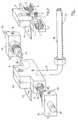
- Fig. 1 is a perspective, partially exploded view of a mixing head used in the invention;
- Fig. 2 is a cut-away view of the mixing head of Fig. 1,
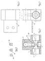
- Fig. 3 is a side view of the mixing head,
- Fig 4 is a plan view of the mixing head;
- Fig 5 is a cross sectional view of the mixing head; and
- Fig. 6 are views of a grub screw used in the mixing head.
- The invention provides a method for manufacturing an insulating body such as an insulating panel in which a high pressure phenolic resin stream is impingement mixed with a low pressure stream to form a phenolic insulating foam reactant mixture.
- Referring to the drawings there is illustrated a
mixing head 1 used in the invention. The mixinghead 1 is typically a stainless steel block having a first highpressure inlet port 2 and a second high pressure inlet port 3 which are oppositely directed. Bothports 2, 3 are connected to a phenolic resin stream at a pressure of at least 100 bar, preferably at least 125 bar, preferably greater than 140 bar, ideally from 170 to 190 bar, typically 180 bar. Thus, two streams of a phenolic resin at a high pressure are directed towards one another and impinge against one another in animpingement mixing chamber 5 in the mixing head. - The mixing
head 1 has a lowpressure inlet port 6 which is connected to a low pressure stream at a low pressure of less than 20 bar, preferably less than 10 bar, ideally from 3 to 10 bar and typically about 5 bar. Theinlet port 6 is perpendicular to thephenolic resin parts 2, 3 and the low pressure stream is drawn into thechamber 5 and is impingement mixed with the high pressure phenolic resin streams. The phenolic insulating foam reactant mixture exits from the mixing chamber through anoutlet 7. - The
outlet 7 is in this case connected by anelbow section 8 to an elongate lay-down poker 10 having a plurality of axially spaced-apart downwardly directed outlet holes through which streams 12 of liquid foam reactants exit. Typically thepoker 10 is moved transversely across a substrate as the substrate is continuously moved along underneath thepoker 10 to achieve an even spread of the phenolic reactants across the length and width of the substrate. A mountingbracket 15 fixed to the mixinghead 1 is mounted to a traversing carriage which moves the poker 11 back and forth across the substrate. - In this case the mixing head comprises a pressurised
air inlet port 20 through which pressurised air is introduced at a pressure of 3 to 8 bar. Typically the air flow is 50 to 150 cc/min. at 6 bar. Such an air stream aerates the mixture and improves foam quality. - It is also envisaged that the mixture may be aerated by, for example, use of an in-line aeration device, or vigorous mixing in the holding tank. However, we have found it most convenient and effective to introduce pressurised air into the mixing chamber.
- The low pressure stream ideally comprises an acid stream. The low pressure stream may also comprise a blowing agent stream which may be introduced through a separate inlet and may be premixed with the acid before contacting the high pressure stream. The introduction of the blowing agent in this way provides improved control of the foaming process and facilitates adjustment during production. It may also contribute to improved foam quality as evidenced by fine cell structure.
- The resin is delivered through
injectors 15. Eachinjector 15 is carried by aholder 16 which is screw threadingly engaged in abore 17 in the mixinghead 1. Eachholder 16 has aninlet 18 for resin and alubrication port 19. Pressure is adjusted by moving a setting screw covered by acap 30. The low pressure inlet is fitted with a grub screw 35 (Fig. 6) which has an orifice of typically 1.5 mm or 3 mm through which the low pressure stream is passed into the mixingchamber 5. The mixinghead 1 has an additional low pressure stream inlet port 6a which may be used, for example, for introduction of a blowing agent. The blowing agent can be added to a resin holding tank, into the resin stream or directly into the mixing head through the inlet 6a. - The acid is mixed with the phenolic resin stream in the mixing head by high pressure impingement mixing. Thus, the residence time of the acid in the mixing head is minimised and the corrosive properties of the acid are counteracted because no separate rotatable mixing element is required. Because the acid and phenolic resin are mixed in-line the mixing head is relatively light and can be mounted directly to a lay down device such as a poker. Most importantly, the distance along which the reactant mixture flows prior to lay down is minimised. Therefore the reactant mixture when laid down is at a very early stage in the foaming reaction and can readily be controlled.
- The method and apparatus of the invention may be utilised in the manufacture of phenolic insulating bodies in any desired form on a batch, semi-continuous or, most importantly on a continuous basis. Thus, the invention can be applied to the manufacture of phenolic insulating panels with or without facings. The facings, when present, may be either flexible or non-flexible. There may be a flexible facing on one face and a non-flexible facing on the opposite face.
- To form a phenolic insulating panel on a continuous basis a first substrate is typically conveyed along a flat bed. Liquid phenolic foam reactants are then laid down onto the first substrate and a second substrate is led continuously over the liquid insulating foam reactants. The substrates and the phenolic foam reactants are heated allowing the reactants to expand and form an insulating core between the substrates.
- Various process enhancements may be adopted to improve the quality of the panel thus formed. Such enhancements are described in UK-A- 2 343 654.
- A phenolic foam mixture is manufactured from the following:
parts by weight output kg/min mixed weight (kg) Phenolic Resin J60/2300 100 11.10 1175 141b/10 % PF5050 8 0.89 94 Phencat 38 PSA 22 2.45 258.5 - The Resin is from Borden Chemicals. 141b is from A-Gas. PF5050 is perfluropentane from 3M. Phencat 38 is phenol sulphuric acid from Libra Chemicals.
- An aerated phenolic resin stream at a temperature of 22.8°C was split into two and the streams were introduced into two separate inlets of an impingement mixing head as described above. A resin pump was run at 80Hz and the resin line pressure to the inlets was 174 bar and 169 bar respectively.
- A stream of acid at ambient temperature was pumped by an acid pump run at 66Hz and delivered into the mixing head at a pressure of 3 bar.
- The foam mixture thus formed was delivered through a lay down poker.
- A roof and wall panel was manufactured by delivering an external profiled metal sheet to a lay-down bed. The foam mixture was laid down onto the sheet using the traversing poker.
- The backing tray was then applied and the composite panel thus formed was cured. The density of the foam was 67.91 kg/m3. The panels were of good quality. Cell structure was very fine and physical properties were good. There was no evidence of streaks or stiations in the foam structure. The average compressive strength was 0.28 N/mm2 and the average compressive modulus was 6.04 N/mm2.
- Example 1 was repeated with flexible aluminum foil facings using varying air injection into the mixer head as follows:
A B J60/2300L (Kg/hr) 411 411 Phencat 38 (L/hr) 69 69 141b/PF5050 (90:10) (Kg/hr) 55 55 Resin Temperature (DegC) 18 18 Emulsion Temperature (DegC) 26 26 Resin Injector Pressures (Bar) 170 170 Air (cc/min) 50 100 Lambda Value (3 days @ 70 Deg C) 0.0210 0.0185 Compressive Strength (Kpa) 77.8 102.6 Density (Kg/m3) 37.9 37.5 - Both foams A and B had good physical characteristics.
- Example 1 was repeated with flexible aluminum foil facings with no aeration as follows:
J60/2300L(Kg/hr) 411 Phencat 38 (L/hr) 69 141b/10%PF5050 55 Resin Temperature (DegC) 18 Emulsion Temperature (DegC) 26 Resin Injector Pressures (Bar) 170 - The foam thus formed had adequate physical properties but not as good as those of Example 2.
Lambda Value (3 days @ 70 Deg C) 0.0310 Compressive Strength (Kpa) 66.7 Density (Kg/m3) 36.8 - Example 2B was repeated using just one resin injector with all other parameters being the same. The resultant foam had the following properties:
Lambda Value (3 days @ 70 Deg C) 0.0234 Compressive Strength (Kpa) 89.9 Density (Kg/m3) 36.5 - The foam had adequate physical properties but not as good as those of Example 2.
- The invention is not limited to the embodiments hereinbefore described which may be varied in detail.
Claims (28)
- A method for manufacturing an insulating body comprising the step of high pressure impingement mixing of a high pressure liquid phenolic resin stream at a pressure of at least 100 bar and a low pressure stream at a pressure of less than 20 bar to form a phenolic insulating foam reactant mixture.
- A method as claimed in claim 1 wherein the low pressure stream comprises an acid stream.
- A method as claimed in claim 1 or 2 wherein the low pressure stream comprises a blowing agent stream.
- A method as claimed in any preceding claim wherein the low pressure stream comprises acid and blowing agent.
- A method as claimed in any of claims 1 to 4 wherein the phenolic resin stream is at a pressure of at least 125 bar.
- A method as claimed in any of claims 1 to 5 wherein the phenolic resin stream is at a pressure of greater than 140 bar.
- A method as claimed in any of claims 1 to 6 wherein the phenolic resin stream is at a pressure of greater than 170 bar.
- A method as claimed in any of claims 1 to 7 wherein the phenolic resin stream is at a pressure of from 170 to 190 bar.
- A method as claimed in any of claims 1 to 8 wherein the low pressure stream is at a pressure of less than 10 bar.
- A method as claimed in any of claims 1 to 9 wherein the low pressure stream is at a pressure of from 3 to 10 bar.
- A method as claimed in any preceding claim wherein the low pressure stream is drawn into the phenolic resin stream through an orifice.
- A method as claimed in any preceding claim including the step of splitting the phenolic resin stream into at least two streams which are directed towards one another and the low pressure stream is drawn in between the high pressure streams.
- A method as claimed in any preceding claim comprising the step of introducing an air stream for aerating the mixture.
- A method as claimed in claim 13 wherein the mixture is aerated by mixing with the high pressure liquid phenolic resin stream and the low pressure stream.
- A method as claimed in claim 14 wherein the air stream is introduced during impingement mixing of the high pressure liquid phenolic resin stream and the low pressure stream.
- A method as claimed in claim 14 or 15 wherein the air stream is at a pressure of from 3 to 8 bar.
- A method as claimed in any preceding claim comprising the steps of: -laying down the liquid phenolic foam reactants onto a first substrate;applying a second substrate over the liquid foam reactants; andheating the substrates and the reactants to allow the phenolic foam reactants to expand and form an insulating core between the substrates.
- A method for manufacturing an insulating panel comprising the steps of:-conveying a first substrate continuously along a flat bed;forming a liquid phenolic foam reactant stream by a method as claimed in any of claims 1 to 17;laying down the liquid phenolic foam reactants onto the first substrate;leading a second substrate continuously over the liquid insulating foam reactants;heating the substrates and the phenolic foam reactants to expand the reactants and form an insulating core between the substrates.
- A method as claimed in claim 17 or 18 wherein the liquid phenolic foam reactants are laid onto the substrate through a lay down poker, preferably the method includes the step of moving the lay down poker relative to the substrate.
- A method as claimed in any of claims 17 to 19 wherein at least one of the substrates is a flexible substrate, preferably at least one of the substrates is a non-flexible substrate such as a metal skin.
- A method for manufacturing an insulating panel comprising the steps of:-introducing a phenolic resin stream into an impingement mixing head, and simultaneously introducing a low pressure stream into the phenolic resin stream at a low pressure of less than 20 bar relative to the high pressure of at least 100 bar of the phenolic resin stream;laying down the liquid phenolic insulating foam reactant mixture thus formed onto a substrate; andheating the reactant mixture in an oven to allow the phenolic foam reactants to expand to form an insulating core.
- A method as claimed in claim 21 wherein the low pressure stream comprises an acid stream.
- A method as claimed in claim 21 or 22 wherein the low pressure stream comprises a blowing agent stream.
- A method as claimed in any of claims 21 to 23 comprising introducing an air stream into the impingement mixing head during introduction of the phenolic resin stream and the low pressure stream.
- Phenolic insulating foam reactant forming apparatus comprising an impingement mixing head for forming a phenolic insulating foam reactant mixture comprising at least one high pressure inlet for a phenolic resin stream at a pressure of at least 100 bar and a low pressure inlet through which a low pressure stream at less than 20 bar is drawn for impingement mixing with the phenolic stream.
- Apparatus as claimed in claim 25 wherein the mixing head comprises at least two high pressure inlets which are directed towards one another.
- Apparatus as claimed in claim 26 comprising two low pressure inlets.
- Apparatus as claimed in claim 26 or 27 comprising an air inlet for introducing pressurised air into the impingement mixing head during mixing of a phenolic resin stream and a low pressure stream.
Priority Applications (1)
| Application Number | Priority Date | Filing Date | Title |
|---|---|---|---|
| EP01984331A EP1311596B1 (en) | 2000-07-21 | 2001-07-23 | Method and apparatus for manufacturing phenolic foams by impingement mixing |
Applications Claiming Priority (6)
| Application Number | Priority Date | Filing Date | Title |
|---|---|---|---|
| EP00650086 | 2000-07-21 | ||
| EP00650086 | 2000-07-21 | ||
| IE010085 | 2001-02-01 | ||
| IE20010085 | 2001-02-01 | ||
| EP01984331A EP1311596B1 (en) | 2000-07-21 | 2001-07-23 | Method and apparatus for manufacturing phenolic foams by impingement mixing |
| PCT/IE2001/000096 WO2002008319A1 (en) | 2000-07-21 | 2001-07-23 | Method and apparatus for manufacturing phenolic foams by impingement mixing |
Publications (2)
| Publication Number | Publication Date |
|---|---|
| EP1311596A1 EP1311596A1 (en) | 2003-05-21 |
| EP1311596B1 true EP1311596B1 (en) | 2006-06-21 |
Family
ID=26073719
Family Applications (1)
| Application Number | Title | Priority Date | Filing Date |
|---|---|---|---|
| EP01984331A Expired - Lifetime EP1311596B1 (en) | 2000-07-21 | 2001-07-23 | Method and apparatus for manufacturing phenolic foams by impingement mixing |
Country Status (6)
| Country | Link |
|---|---|
| EP (1) | EP1311596B1 (en) |
| AT (1) | ATE330988T1 (en) |
| AU (1) | AU2002224548A1 (en) |
| DE (1) | DE60120993T2 (en) |
| GB (1) | GB2364938B (en) |
| WO (1) | WO2002008319A1 (en) |
Families Citing this family (1)
| Publication number | Priority date | Publication date | Assignee | Title |
|---|---|---|---|---|
| IE20070752A1 (en) | 2006-10-17 | 2008-06-11 | Kingspan Res & Dev Ltd | An insulating medium |
Family Cites Families (2)
| Publication number | Priority date | Publication date | Assignee | Title |
|---|---|---|---|---|
| FR2623121B1 (en) * | 1987-11-16 | 1993-10-01 | Cappello Lucio | PROCESS FOR MAKING BY INJECTION PARTS OF COMPOSITE MATERIALS CONTAINING REINFORCEMENT FIBERS IN A LIGHT SYNTHETIC RESIN MATRIX BY INCORPORATING GAS |
| DE19706030C2 (en) * | 1997-02-17 | 2000-07-06 | Bayer Ag | Method and device for producing filler-containing polyurethanes |
-
2001
- 2001-07-23 EP EP01984331A patent/EP1311596B1/en not_active Expired - Lifetime
- 2001-07-23 AT AT01984331T patent/ATE330988T1/en not_active IP Right Cessation
- 2001-07-23 WO PCT/IE2001/000096 patent/WO2002008319A1/en not_active Ceased
- 2001-07-23 AU AU2002224548A patent/AU2002224548A1/en not_active Abandoned
- 2001-07-23 DE DE60120993T patent/DE60120993T2/en not_active Expired - Lifetime
- 2001-07-23 GB GB0117930A patent/GB2364938B/en not_active Expired - Fee Related
Also Published As
| Publication number | Publication date |
|---|---|
| GB0117930D0 (en) | 2001-09-12 |
| WO2002008319A1 (en) | 2002-01-31 |
| DE60120993D1 (en) | 2006-08-03 |
| AU2002224548A1 (en) | 2002-02-05 |
| IE20010688A1 (en) | 2002-04-03 |
| ATE330988T1 (en) | 2006-07-15 |
| GB2364938B (en) | 2004-05-26 |
| GB2364938A (en) | 2002-02-13 |
| DE60120993T2 (en) | 2007-01-11 |
| EP1311596A1 (en) | 2003-05-21 |
Similar Documents
| Publication | Publication Date | Title |
|---|---|---|
| EP0787034B1 (en) | Method and apparatus for producing closed cell foam | |
| USRE37012E1 (en) | Froth system for continuous manufacture of polyurethane foam slab-stocks | |
| EP0683027A2 (en) | Method and apparatus for dispensing foam materials | |
| EP2585203B1 (en) | Static reactive jet mixer, and method of mixing during an amine-phosgene mixing process | |
| US5620710A (en) | Froth system for continuous manufacture of polyurethane foam slab-stocks | |
| DE69903459T2 (en) | POLYURETHANE FOAM AND THERMAL INSULATING COMPONENT | |
| TW200940309A (en) | Process for producing heat curing resin foamed plate | |
| JP2012516791A (en) | High pressure equipment | |
| JPH05154932A (en) | Method and device for manufacturing foamed synthetic resin plate | |
| JPH01138244A (en) | Production of closed cell phenol resin foam | |
| EP1311596A1 (en) | Method and apparatus for manufacturing phenolic foams by impingement mixing | |
| EP0530510A1 (en) | Cement paste mixer and method for producing mortar and concrete | |
| IES83817Y1 (en) | A method and apparatus for manufacturing an insulating body | |
| IE83469B1 (en) | A method and apparatus for manufacturing an insulating body | |
| DE102007014768B4 (en) | Method and device for the production of insulating elements | |
| EP0018061A1 (en) | Methods for the manufacture of sheets or moulded bodies | |
| US20050242457A1 (en) | Composite decking | |
| CN1113732C (en) | Process for making reaction mixtures from isocyanate and polyol formulations | |
| DE102005048874A1 (en) | Production of fibre-reinforced plastic mouldings or coatings involves mixing e.g. chopped glass fibres with polyurethane starting mixture in a special mixing system and spraying directly onto a substrate | |
| JPS5816838A (en) | Manufacture of phenol resin foam | |
| CN218488919U (en) | Liquid carbon dioxide sponge foaming equipment | |
| US7293594B2 (en) | Process for the production of sandwich elements from reactive plastics material | |
| JPS61141511A (en) | Manufacture of inorganic and organic composite foam | |
| US20070080171A1 (en) | Method and apparatus for applying a foam layer | |
| KR100322320B1 (en) | Process for Continuous Production of Flowable, Foamable and Curable Phenolic Resol Resin Mixtures |
Legal Events
| Date | Code | Title | Description |
|---|---|---|---|
| PUAI | Public reference made under article 153(3) epc to a published international application that has entered the european phase |
Free format text: ORIGINAL CODE: 0009012 |
|
| 17P | Request for examination filed |
Effective date: 20021213 |
|
| AK | Designated contracting states |
Designated state(s): AT BE CH CY DE DK ES FI FR GB GR IE IT LI LU MC NL PT SE TR |
|
| AX | Request for extension of the european patent |
Extension state: AL LT LV MK RO SI |
|
| 17Q | First examination report despatched |
Effective date: 20041222 |
|
| GRAP | Despatch of communication of intention to grant a patent |
Free format text: ORIGINAL CODE: EPIDOSNIGR1 |
|
| GRAS | Grant fee paid |
Free format text: ORIGINAL CODE: EPIDOSNIGR3 |
|
| RBV | Designated contracting states (corrected) |
Designated state(s): AT BE CH CY DE DK ES FI FR GR IT LI LU MC NL PT SE TR |
|
| GRAA | (expected) grant |
Free format text: ORIGINAL CODE: 0009210 |
|
| AK | Designated contracting states |
Kind code of ref document: B1 Designated state(s): AT BE CH CY DE DK ES FI FR GR IT LI LU MC NL PT SE TR |
|
| PG25 | Lapsed in a contracting state [announced via postgrant information from national office to epo] |
Ref country code: FI Free format text: LAPSE BECAUSE OF FAILURE TO SUBMIT A TRANSLATION OF THE DESCRIPTION OR TO PAY THE FEE WITHIN THE PRESCRIBED TIME-LIMIT Effective date: 20060621 Ref country code: AT Free format text: LAPSE BECAUSE OF FAILURE TO SUBMIT A TRANSLATION OF THE DESCRIPTION OR TO PAY THE FEE WITHIN THE PRESCRIBED TIME-LIMIT Effective date: 20060621 |
|
| REG | Reference to a national code |
Ref country code: CH Ref legal event code: EP |
|
| PG25 | Lapsed in a contracting state [announced via postgrant information from national office to epo] |
Ref country code: MC Free format text: LAPSE BECAUSE OF NON-PAYMENT OF DUE FEES Effective date: 20060731 |
|
| REF | Corresponds to: |
Ref document number: 60120993 Country of ref document: DE Date of ref document: 20060803 Kind code of ref document: P |
|
| REG | Reference to a national code |
Ref country code: CH Ref legal event code: NV Representative=s name: ISLER & PEDRAZZINI AG |
|
| PG25 | Lapsed in a contracting state [announced via postgrant information from national office to epo] |
Ref country code: SE Free format text: LAPSE BECAUSE OF FAILURE TO SUBMIT A TRANSLATION OF THE DESCRIPTION OR TO PAY THE FEE WITHIN THE PRESCRIBED TIME-LIMIT Effective date: 20060921 Ref country code: DK Free format text: LAPSE BECAUSE OF FAILURE TO SUBMIT A TRANSLATION OF THE DESCRIPTION OR TO PAY THE FEE WITHIN THE PRESCRIBED TIME-LIMIT Effective date: 20060921 |
|
| PG25 | Lapsed in a contracting state [announced via postgrant information from national office to epo] |
Ref country code: ES Free format text: LAPSE BECAUSE OF FAILURE TO SUBMIT A TRANSLATION OF THE DESCRIPTION OR TO PAY THE FEE WITHIN THE PRESCRIBED TIME-LIMIT Effective date: 20061002 |
|
| PG25 | Lapsed in a contracting state [announced via postgrant information from national office to epo] |
Ref country code: PT Free format text: LAPSE BECAUSE OF FAILURE TO SUBMIT A TRANSLATION OF THE DESCRIPTION OR TO PAY THE FEE WITHIN THE PRESCRIBED TIME-LIMIT Effective date: 20061121 |
|
| ET | Fr: translation filed | ||
| PLBE | No opposition filed within time limit |
Free format text: ORIGINAL CODE: 0009261 |
|
| STAA | Information on the status of an ep patent application or granted ep patent |
Free format text: STATUS: NO OPPOSITION FILED WITHIN TIME LIMIT |
|
| 26N | No opposition filed |
Effective date: 20070322 |
|
| REG | Reference to a national code |
Ref country code: CH Ref legal event code: PCAR Free format text: ISLER & PEDRAZZINI AG;POSTFACH 1772;8027 ZUERICH (CH) |
|
| PG25 | Lapsed in a contracting state [announced via postgrant information from national office to epo] |
Ref country code: GR Free format text: LAPSE BECAUSE OF FAILURE TO SUBMIT A TRANSLATION OF THE DESCRIPTION OR TO PAY THE FEE WITHIN THE PRESCRIBED TIME-LIMIT Effective date: 20060922 |
|
| PG25 | Lapsed in a contracting state [announced via postgrant information from national office to epo] |
Ref country code: TR Free format text: LAPSE BECAUSE OF FAILURE TO SUBMIT A TRANSLATION OF THE DESCRIPTION OR TO PAY THE FEE WITHIN THE PRESCRIBED TIME-LIMIT Effective date: 20060621 |
|
| PG25 | Lapsed in a contracting state [announced via postgrant information from national office to epo] |
Ref country code: CY Free format text: LAPSE BECAUSE OF FAILURE TO SUBMIT A TRANSLATION OF THE DESCRIPTION OR TO PAY THE FEE WITHIN THE PRESCRIBED TIME-LIMIT Effective date: 20060621 |
|
| PGFP | Annual fee paid to national office [announced via postgrant information from national office to epo] |
Ref country code: LU Payment date: 20130725 Year of fee payment: 13 |
|
| PGFP | Annual fee paid to national office [announced via postgrant information from national office to epo] |
Ref country code: CH Payment date: 20130725 Year of fee payment: 13 |
|
| PGFP | Annual fee paid to national office [announced via postgrant information from national office to epo] |
Ref country code: IT Payment date: 20130727 Year of fee payment: 13 |
|
| PG25 | Lapsed in a contracting state [announced via postgrant information from national office to epo] |
Ref country code: LU Free format text: LAPSE BECAUSE OF NON-PAYMENT OF DUE FEES Effective date: 20140723 |
|
| REG | Reference to a national code |
Ref country code: CH Ref legal event code: PL |
|
| PG25 | Lapsed in a contracting state [announced via postgrant information from national office to epo] |
Ref country code: CH Free format text: LAPSE BECAUSE OF NON-PAYMENT OF DUE FEES Effective date: 20140731 Ref country code: IT Free format text: LAPSE BECAUSE OF NON-PAYMENT OF DUE FEES Effective date: 20140723 Ref country code: LI Free format text: LAPSE BECAUSE OF NON-PAYMENT OF DUE FEES Effective date: 20140731 |
|
| REG | Reference to a national code |
Ref country code: FR Ref legal event code: PLFP Year of fee payment: 15 |
|
| PGFP | Annual fee paid to national office [announced via postgrant information from national office to epo] |
Ref country code: NL Payment date: 20150722 Year of fee payment: 15 |
|
| PGFP | Annual fee paid to national office [announced via postgrant information from national office to epo] |
Ref country code: FR Payment date: 20150630 Year of fee payment: 15 Ref country code: BE Payment date: 20150731 Year of fee payment: 15 |
|
| PGFP | Annual fee paid to national office [announced via postgrant information from national office to epo] |
Ref country code: DE Payment date: 20150930 Year of fee payment: 15 |
|
| PG25 | Lapsed in a contracting state [announced via postgrant information from national office to epo] |
Ref country code: BE Free format text: LAPSE BECAUSE OF NON-PAYMENT OF DUE FEES Effective date: 20160731 |
|
| REG | Reference to a national code |
Ref country code: DE Ref legal event code: R119 Ref document number: 60120993 Country of ref document: DE |
|
| REG | Reference to a national code |
Ref country code: NL Ref legal event code: MM Effective date: 20160801 |
|
| PG25 | Lapsed in a contracting state [announced via postgrant information from national office to epo] |
Ref country code: DE Free format text: LAPSE BECAUSE OF NON-PAYMENT OF DUE FEES Effective date: 20170201 Ref country code: FR Free format text: LAPSE BECAUSE OF NON-PAYMENT OF DUE FEES Effective date: 20160801 Ref country code: NL Free format text: LAPSE BECAUSE OF NON-PAYMENT OF DUE FEES Effective date: 20160801 |
|
| REG | Reference to a national code |
Ref country code: FR Ref legal event code: ST Effective date: 20170331 |