EP1311336B1 - Production of nitrogen for on-site injection in well clean out - Google Patents
Production of nitrogen for on-site injection in well clean outInfo
- Publication number
- EP1311336B1 EP1311336B1 EP01958218A EP01958218A EP1311336B1 EP 1311336 B1 EP1311336 B1 EP 1311336B1 EP 01958218 A EP01958218 A EP 01958218A EP 01958218 A EP01958218 A EP 01958218A EP 1311336 B1 EP1311336 B1 EP 1311336B1
- Authority
- EP
- European Patent Office
- Prior art keywords
- well
- nitrogen
- rich gas
- gas
- nitrogen rich
- Prior art date
- Legal status (The legal status is an assumption and is not a legal conclusion. Google has not performed a legal analysis and makes no representation as to the accuracy of the status listed.)
- Expired - Lifetime
Links
- IJGRMHOSHXDMSA-UHFFFAOYSA-N Atomic nitrogen Chemical compound N#N IJGRMHOSHXDMSA-UHFFFAOYSA-N 0.000 title claims description 142
- 229910052757 nitrogen Inorganic materials 0.000 title claims description 66
- 238000004519 manufacturing process Methods 0.000 title claims description 37
- 238000002347 injection Methods 0.000 title 1
- 239000007924 injection Substances 0.000 title 1
- 238000000034 method Methods 0.000 claims abstract description 30
- 238000004140 cleaning Methods 0.000 claims abstract description 15
- 239000013618 particulate matter Substances 0.000 claims abstract description 5
- 239000007789 gas Substances 0.000 claims description 67
- QVGXLLKOCUKJST-UHFFFAOYSA-N atomic oxygen Chemical compound [O] QVGXLLKOCUKJST-UHFFFAOYSA-N 0.000 claims description 17
- 239000001301 oxygen Substances 0.000 claims description 17
- 229910052760 oxygen Inorganic materials 0.000 claims description 17
- 239000012528 membrane Substances 0.000 claims description 16
- 238000001179 sorption measurement Methods 0.000 claims description 15
- 229910001873 dinitrogen Inorganic materials 0.000 claims description 10
- 239000000463 material Substances 0.000 claims description 9
- 239000002912 waste gas Substances 0.000 claims description 8
- 239000006260 foam Substances 0.000 claims description 7
- 230000002401 inhibitory effect Effects 0.000 claims description 4
- 239000004094 surface-active agent Substances 0.000 claims description 3
- 239000000654 additive Substances 0.000 claims 2
- 230000000996 additive effect Effects 0.000 claims 2
- 230000002745 absorbent Effects 0.000 claims 1
- 239000002250 absorbent Substances 0.000 claims 1
- 239000011261 inert gas Substances 0.000 abstract description 13
- 238000000926 separation method Methods 0.000 abstract description 13
- 239000003570 air Substances 0.000 description 40
- VYPSYNLAJGMNEJ-UHFFFAOYSA-N Silicium dioxide Chemical compound O=[Si]=O VYPSYNLAJGMNEJ-UHFFFAOYSA-N 0.000 description 7
- 239000000047 product Substances 0.000 description 6
- 239000004576 sand Substances 0.000 description 6
- 238000003860 storage Methods 0.000 description 6
- 238000005553 drilling Methods 0.000 description 5
- 239000012530 fluid Substances 0.000 description 5
- 238000009434 installation Methods 0.000 description 5
- 239000007788 liquid Substances 0.000 description 4
- 230000037361 pathway Effects 0.000 description 4
- 239000000126 substance Substances 0.000 description 4
- XLYOFNOQVPJJNP-UHFFFAOYSA-N water Substances O XLYOFNOQVPJJNP-UHFFFAOYSA-N 0.000 description 4
- 239000000835 fiber Substances 0.000 description 3
- 238000010926 purge Methods 0.000 description 3
- 230000008929 regeneration Effects 0.000 description 3
- 238000011069 regeneration method Methods 0.000 description 3
- 239000003463 adsorbent Substances 0.000 description 2
- 230000015572 biosynthetic process Effects 0.000 description 2
- 238000011010 flushing procedure Methods 0.000 description 2
- 239000004088 foaming agent Substances 0.000 description 2
- 238000005755 formation reaction Methods 0.000 description 2
- MYMOFIZGZYHOMD-UHFFFAOYSA-N Dioxygen Chemical compound O=O MYMOFIZGZYHOMD-UHFFFAOYSA-N 0.000 description 1
- 238000009825 accumulation Methods 0.000 description 1
- 239000012080 ambient air Substances 0.000 description 1
- 239000006227 byproduct Substances 0.000 description 1
- 238000002485 combustion reaction Methods 0.000 description 1
- 230000006835 compression Effects 0.000 description 1
- 238000007906 compression Methods 0.000 description 1
- 238000010276 construction Methods 0.000 description 1
- 238000001816 cooling Methods 0.000 description 1
- 238000005520 cutting process Methods 0.000 description 1
- 230000003292 diminished effect Effects 0.000 description 1
- 229910001882 dioxygen Inorganic materials 0.000 description 1
- 238000009826 distribution Methods 0.000 description 1
- 239000000446 fuel Substances 0.000 description 1
- 230000004941 influx Effects 0.000 description 1
- 230000005012 migration Effects 0.000 description 1
- 238000013508 migration Methods 0.000 description 1
- 239000002808 molecular sieve Substances 0.000 description 1
- 238000012856 packing Methods 0.000 description 1
- 239000000741 silica gel Substances 0.000 description 1
- 229910002027 silica gel Inorganic materials 0.000 description 1
- URGAHOPLAPQHLN-UHFFFAOYSA-N sodium aluminosilicate Chemical compound [Na+].[Al+3].[O-][Si]([O-])=O.[O-][Si]([O-])=O URGAHOPLAPQHLN-UHFFFAOYSA-N 0.000 description 1
- 230000004936 stimulating effect Effects 0.000 description 1
- 230000000638 stimulation Effects 0.000 description 1
Images



Classifications
-
- E—FIXED CONSTRUCTIONS
- E21—EARTH OR ROCK DRILLING; MINING
- E21B—EARTH OR ROCK DRILLING; OBTAINING OIL, GAS, WATER, SOLUBLE OR MELTABLE MATERIALS OR A SLURRY OF MINERALS FROM WELLS
- E21B37/00—Methods or apparatus for cleaning boreholes or wells
- E21B37/06—Methods or apparatus for cleaning boreholes or wells using chemical means for preventing or limiting, e.g. eliminating, the deposition of paraffins or like substances
-
- B—PERFORMING OPERATIONS; TRANSPORTING
- B01—PHYSICAL OR CHEMICAL PROCESSES OR APPARATUS IN GENERAL
- B01D—SEPARATION
- B01D53/00—Separation of gases or vapours; Recovering vapours of volatile solvents from gases; Chemical or biological purification of waste gases, e.g. engine exhaust gases, smoke, fumes, flue gases, aerosols
- B01D53/02—Separation of gases or vapours; Recovering vapours of volatile solvents from gases; Chemical or biological purification of waste gases, e.g. engine exhaust gases, smoke, fumes, flue gases, aerosols by adsorption, e.g. preparative gas chromatography
- B01D53/04—Separation of gases or vapours; Recovering vapours of volatile solvents from gases; Chemical or biological purification of waste gases, e.g. engine exhaust gases, smoke, fumes, flue gases, aerosols by adsorption, e.g. preparative gas chromatography with stationary adsorbents
- B01D53/047—Pressure swing adsorption
-
- B—PERFORMING OPERATIONS; TRANSPORTING
- B01—PHYSICAL OR CHEMICAL PROCESSES OR APPARATUS IN GENERAL
- B01D—SEPARATION
- B01D53/00—Separation of gases or vapours; Recovering vapours of volatile solvents from gases; Chemical or biological purification of waste gases, e.g. engine exhaust gases, smoke, fumes, flue gases, aerosols
- B01D53/22—Separation of gases or vapours; Recovering vapours of volatile solvents from gases; Chemical or biological purification of waste gases, e.g. engine exhaust gases, smoke, fumes, flue gases, aerosols by diffusion
-
- B—PERFORMING OPERATIONS; TRANSPORTING
- B01—PHYSICAL OR CHEMICAL PROCESSES OR APPARATUS IN GENERAL
- B01D—SEPARATION
- B01D2253/00—Adsorbents used in seperation treatment of gases and vapours
- B01D2253/10—Inorganic adsorbents
- B01D2253/106—Silica or silicates
-
- B—PERFORMING OPERATIONS; TRANSPORTING
- B01—PHYSICAL OR CHEMICAL PROCESSES OR APPARATUS IN GENERAL
- B01D—SEPARATION
- B01D2253/00—Adsorbents used in seperation treatment of gases and vapours
- B01D2253/10—Inorganic adsorbents
- B01D2253/106—Silica or silicates
- B01D2253/108—Zeolites
-
- B—PERFORMING OPERATIONS; TRANSPORTING
- B01—PHYSICAL OR CHEMICAL PROCESSES OR APPARATUS IN GENERAL
- B01D—SEPARATION
- B01D2256/00—Main component in the product gas stream after treatment
- B01D2256/10—Nitrogen
-
- B—PERFORMING OPERATIONS; TRANSPORTING
- B01—PHYSICAL OR CHEMICAL PROCESSES OR APPARATUS IN GENERAL
- B01D—SEPARATION
- B01D2257/00—Components to be removed
- B01D2257/10—Single element gases other than halogens
- B01D2257/104—Oxygen
-
- B—PERFORMING OPERATIONS; TRANSPORTING
- B01—PHYSICAL OR CHEMICAL PROCESSES OR APPARATUS IN GENERAL
- B01D—SEPARATION
- B01D2259/00—Type of treatment
- B01D2259/40—Further details for adsorption processes and devices
- B01D2259/40011—Methods relating to the process cycle in pressure or temperature swing adsorption
- B01D2259/40043—Purging
- B01D2259/4005—Nature of purge gas
- B01D2259/40052—Recycled product or process gas
-
- B—PERFORMING OPERATIONS; TRANSPORTING
- B01—PHYSICAL OR CHEMICAL PROCESSES OR APPARATUS IN GENERAL
- B01D—SEPARATION
- B01D2259/00—Type of treatment
- B01D2259/40—Further details for adsorption processes and devices
- B01D2259/402—Further details for adsorption processes and devices using two beds
-
- B—PERFORMING OPERATIONS; TRANSPORTING
- B01—PHYSICAL OR CHEMICAL PROCESSES OR APPARATUS IN GENERAL
- B01D—SEPARATION
- B01D53/00—Separation of gases or vapours; Recovering vapours of volatile solvents from gases; Chemical or biological purification of waste gases, e.g. engine exhaust gases, smoke, fumes, flue gases, aerosols
- B01D53/02—Separation of gases or vapours; Recovering vapours of volatile solvents from gases; Chemical or biological purification of waste gases, e.g. engine exhaust gases, smoke, fumes, flue gases, aerosols by adsorption, e.g. preparative gas chromatography
- B01D53/04—Separation of gases or vapours; Recovering vapours of volatile solvents from gases; Chemical or biological purification of waste gases, e.g. engine exhaust gases, smoke, fumes, flue gases, aerosols by adsorption, e.g. preparative gas chromatography with stationary adsorbents
- B01D53/047—Pressure swing adsorption
- B01D53/053—Pressure swing adsorption with storage or buffer vessel
Definitions
- the present invention is directed to methods of cleaning out wells using an inert gas. More specifically, the invention is directed to methods of cleaning out wells which employ an inert gas in a region of the well where collected matter has inhibited the ability of the well to produce.
- the inert gas typically nitrogen gas, is supplied on-site by the separation of air using a membrane or a pressure swing adsorption system.
- a fluid In the cleaning out of oil or gas or geothermal wells, a fluid is typically delivered to a particular area of the well. For example, in a cleaning out operation, fluid must be introduced in the area of the well to be cleaned to remove the sand, scale or other substances that have effected the ability of the well to produce.
- One such fluid includes a foam consisting of nitrogen gas and liquid. Nitrogen can also be combined with a surfactant, foaming agent or water for different applications, like well treating.
- One method of cleaning out a well includes the use of air cooled to cryogenic temperatures.
- the frozen air not only reduces the threat of downhole combustion but also freezes the ground to prevent the influx of water during clean out.
- cooling to cryogenic temperatures is costly and requires additional heavy equipment which may not be readily available, particularly when the well is in a remote location like offshore.
- liquid nitrogen as the source of gas. Liquid nitrogen, however, is disadvantageous because it is considerably more expensive to use than air and difficult to obtain in remote locations.
- an inert gas typically nitrogen gas
- an inert gas typically nitrogen gas
- US-A-3662828 describes a method of cleaning out a well by inserting a flushing tube through production tubing in the well, and injecting foam into the flushing tube.
- US-A-5388650 describes a method of drilling a well, including providing inert gas to the drilling region.
- the gas is used to carry drill cuttings to the surface of the well.
- the inert gas is produced by separation of nitrogen from air.
- GB-A-2186682 describes a method of producing nitrogen from air by pressure swing adsorption.
- a method for cleaning out a well in which production is inhibited comprising removing at least a substantial portion of the oxygen contained within a feed stream of air at the site of said well to produce a pressurised nitrogen rich gas and an oxygen enriched waste gas, and delivering the nitrogen rich gas through coiled tubing to the area of the well to be cleaned out, whereby material inhibiting the production of the well is relocated.
- the invention is directed to a method for cleaning out oil and/or gas or a geothermal wells in which a compressed inert gas is delivered to the area of the well where production is inhibited.
- the inert gas is obtained from an on-site, non-cryogenic source.
- the source of the inert gas is air which is preferentially separated into an inert gas rich fraction and an oxygen waste gas fraction such as by membrane separation or by pressure swing adsorption, for example.
- the present invention is directed to the on-site, non-cryogenic production of an inert gas, typically a nitrogen rich gas and its delivery in the cleaning out of oil and/or gas or geothermal wells.
- an inert gas typically a nitrogen rich gas
- nitrogen rich gas shall refer to a gas containing predominantly nitrogen gas and no more than 10% oxygen gas by volume.
- the nitrogen rich gas is produced from air by a number of different methods including membrane separation, pressure swing adsorption, vacuum swing adsorption and fuel cells. The methods of production are described in U.S. Patent No. 5,388,650 to Michael.
- a feed air compressor 2 includes an intake port 4 for receiving ambient air and a compressor 6 for pressurising the air to a suitable pressure, typically in the range from about 100 to 350 psig (690 to 2400 kN).
- the compressed air is sent through a conduit 8 to an air separation membrane system shown generally by numeral 10.
- the membrane is composed of bundles of hollow fibre, semi-permeable membranes which are assembled parallel to a central core tube. The bundle is placed into an outer case to form an air separation module. The air is divided into two streams; a nitrogen rich stream and a stream rich in oxygen and water vapour.
- the compressed air When the compressed air is introduced to the feed side of the membrane fibres, the air travels down the bore of the hollow permeable fibres. Oxygen, water vapour and other "fast gases" pass through to the outside of the fibres. The oxygen-rich gas stream then flows through the fibre bundle to the periphery of the outer case of the separator system where it is discharged as a by-product. While all but a small fraction of the oxygen passes through the membrane material to the exterior of the hollow fibres, most of the nitrogen present in the feed air is contained within the hollow fibre membrane. As a result, the nitrogen rich gas is effectively separated from the feed air and exits the membrane system 10 via a conduit 12 for entry into an optional booster compressor 14.
- the booster compressor 14 is employed to elevate the pressure of the nitrogen rich gas.
- the pressure of the gas obtained from the air separation membrane system 10 is from about 100 to 200 psig (690 to 1400 kN).
- the booster compressor 14 is capable of raising the pressure of the nitrogen rich gas up to or exceeding 4500 psig (31 ⁇ 10 6 N) and even as high as about 10,000 psig (69 ⁇ 10 6 N), but typically in the range of from about 1,000 to 2,000 psig (6.9 ⁇ 10 6 to 14 ⁇ 10 6 N).
- the highly compressed nitrogen rich gas leaves the booster compressor 14 via a conduit 16 and is sent to a surface equipment installation 18 of the drilling operation as explained in detail hereinafter.
- the nitrogen rich gas may also be produced by a pressure swing adsorption system in accordance with the present invention.
- a pressure swing adsorption unit 20 having two beds “A" and "B". It should be understood, however, that the present invention is applicable to pressure swing adsorption units having an alternate construction such as a greater number of beds.
- air from a source (not shown) is fed to a compressor 6 to raise the pressure of the air, to accumulate compressed air during the non-production phase and to output compressed air during peak loading of the beds.
- the compressed air is fed to a storage vessel 22.
- the compressed air is then fed via the conduit 24, 26 to an outlet 28 leading to bed A and an outlet 30, leading to bed B.
- Each outlet 28, 30 is controlled by respective valves 32, 34.
- valve 32 When valve 32 is opened, allowing the compressed air to reach bed A, valve 34 remains closed so that bed B may undergo regeneration during the depressurisation phase of the pressure swing adsorption unit 20.
- the compressed air enters the bed A through the open valve 32 via a conduit 36.
- the bed A contains at least one adsorption material capable of preferentially adsorbing oxygen and other waste gases.
- the preferred adsorbents are selected from molecular sieves and silica gel.
- bed B While bed A is producing nitrogen gas, bed B is at atmospheric pressure. Upon completion of the nitrogen production cycle in bed A, the system undergoes equalisation to raise the pressure in bed B to an intermediate pressure. This is accomplished by closing the nitrogen product valves 40, 46 and the compressed air intake valves 32, 34. Thus, the input of compressed air and the output of nitrogen product are temporarily suspended. Equalisation is accomplished by passing a portion of the pressurised gas from the top of the bed A via a conduit 38, valve 50, a conduit 52, restrictive orifice 54, through a conduit 56 and into the top of the bed B. In addition, pressurised gas is passed from the bottom of the bed A via the conduit 36, a valve 58, a conduit 60, a restrictive orifice 62 and a conduit 64 into the bottom of bed B.
- bed A undergoes regeneration by depressurising to atmospheric pressure to remove the oxygen enriched waste gases. This is accomplished by closing the equalisation valves 50, 58 and opening a regeneration valve 66 for the bed A. The waste gas is then vented to the atmosphere through a conduit 68 and a restrictive orifice 70. As a consequence, the bed A is regenerated. Further cleansing of the bed A may be made by passing a purge gas, such as substantially pure nitrogen gas, from a source 72, through conduits 74 and 76, respectively, a valve 78 and into bed A via the line 38.
- a purge gas such as substantially pure nitrogen gas
- the purge gas passes through the conduits 74 and 76, respectively, a valve 80 and the conduit 56. After purging, the adsorbents are ready for adsorbing waste gases in a new nitrogen production cycle.
- the pressure in bed B Since the pressure in bed B has been raised to an intermediate pressure, it is ready to receive compressed air.
- the compressed air is provided through the valve 34 and the conduit 64. It may be necessary, in order to get sufficient compressed air to quickly load bed B up to operating pressure, for the compressed air feed generated by the compressor 6 to be supplemented by compressed air already stored in the storage vessel 22.
- the valve 46 Once bed B has been loaded, the valve 46 is opened, allowing product gas to enter the product line 44 via the conduit 56 from which it enters the storage vessel 42.
- a distribution conduit 82 extends from the storage vessel 42 to provide a flow of nitrogen rich product gas to the booster compressor 14 shown in Figure 1. After nitrogen production in bed B is completed, the valve 46 is closed as is the valve 34 to stop the compressed air feed.
- the equalisation circuit is activated by opening valves 50, 58 and the pressurised gas is fed from the top and bottom of bed B to bed A to raise the pressure therein to an intermediate pressure level.
- Bed B is then depressurised by eliminating the oxygen rich waste gases which are sent via the conduits 64, 84 through a valve 86 to the atmosphere via the conduit 68 and restrictive orifice 70.
- compressed air from the compressor 6 and the storage vessel 22 is fed to bed A through the valve 32 via the conduit 36 to raise bed A to the desired operating pressure thereby commencing the nitrogen production cycle from bed A which passes into the booster compressor 14.
- the nitrogen rich gas after compression up to as high as 10,000 psig (69 ⁇ 10 6 N) in the booster compressor 14, is sent to surface equipment installation shown in Figure 4, where it is used in the cleaning out of the well shown in Figure 5.
- the high pressure nitrogen rich gas is delivered to the wellbore from a source 120 through coiled tubing 100.
- the coiled tubing is charged with the gas at a reel 105 and extends through a stripper assembly 110.
- the flow rate of the nitrogen rich gas is typically measured by an orifice meter and is sent through an adjustable choke and a pressure shut off valve (not shown) before entering the wellbore.
- Foam can be added to the gas if it is required for downhole circulation. The foam is used to assist in well stimulation or removal of the sand, scale or other matter inhibiting the production of the well.
- the surface installation may optionally include an injector manifold for injecting chemicals, such as surfactants and special foaming agents, into the nitrogen rich gas feed stream to help dissolve and carry away particulate matter or to provide a low density, low velocity circulation medium of stiff and stable foam chemicals to cause minimum disturbance to unstable or unconsolidated formations.
- chemicals such as surfactants and special foaming agents
- Figure 5 is a section view of a cased wellbore 200 with production tubing 202 extending to a location adjacent casing perforations 205.
- An annular area 216 is isolated by upper and lower packing members 207, 208.
- the production fluid enters production tubing 202 through a perforated screen member 215.
- annular area 216 is packed with gravel to encourage migration of production fluid from the surrounding formation into the wellbore.
- sand shown as 220
- FIG. 6 illustrates one embodiment of the cleaning out method of the present invention in progress.
- Coiled tubing 100 (see also Figure 4) has been inserted into the production tubing 202 to provide a pathway for the flow of pressurised nitrogen rich gas (shown as bubbles 230) from the surface of the well to the area of the well to be cleaned out.
- pressurised nitrogen rich gas shown as bubbles 230
- An annular area 231 formed between the coiled tubing 100 and the production tubing 202 provides a pathway for the return nitrogen rich gas and with it, particulate matter, like sand, to the surface of the well where it is collected and disposed of
- the coiled tubing 100 is typically pumped up and down in the area of particulate matter, in order to agitate the material and to facilitate its removal during the clean out.
- the nitrogen rich gas produced by the air separation membrane system 10 or the pressure swing adsorption unit 20 or other non-cryogenic system typically has a nitrogen content of at least about 85% by volume, preferably at least about 95% by volume, and an oxygen content of no more than 10% by volume, preferably less than about 5% by volume.
- the nitrogen rich gas is sent to a booster compressor 14 where the pressure is raised to as high as 10,000 psig (69 ⁇ 10 6 N) or more, typically in the range of about 1,000 to 2,000 psig (6.9 ⁇ 10 6 to 14 ⁇ 10 6 N).
- the pressurised nitrogen rich gas is sent to the surface equipment shown in Figure 4 where it is monitored and metered into the wellbore through the pathway within the coiled tubing 100.
- the nitrogen rich gas is under pressure, it swirls around the area to be cleaned out with sufficient force and velocity to carry the particulates upward into the pathway created within annular area 231.
- the particulate-containing stream then exits the production tubing at the surface of the well where it is carried to a blooey line and eventually discarded into a collection facility, typically at a location remote from the actual well site.
- a typical well cleanout is performed in a series of sequential steps.
- nitrogen is produced on site using any of the foregoing methods.
- coiled tubing is placed in the well and lowered a predetermined distance to the area of the well where production is inhibited.
- the gas, as well as foam is introduced simultaneously into the coiled tubing.
- the coiled tubing is pumped up and down in the well to agitate the substance inhibiting production and encourage its removal.
- Fifth, the return of material at the surface is measured and monitored.
- the cleanout operation is discontinued.
- the flow rate of nitrogen rich gas to the drilling region of an oil and/or gas well or a geothermal well can vary over a wide range depending on the size of the downhole, the depth of the well, the rate of production and, the size of the production tubing.
- a typical cleaning out operation will require the production of from 1,500 to 3,000 standard cubic feet per minute (scfm) (700 to 1400 litres per second) of nitrogen gas from an air separation system which can be anyone of a number of conventional systems including an air membrane separation system or a pressure swing adsorption system.
- the purity of the nitrogen gas may vary, but is nominally set at no more than about 5% by volume of oxygen.
- the resulting nitrogen rich gas is then pressurised up to a pressure of from about 1,500 to 2,000 psig (10 ⁇ 10 6 to 14 ⁇ 10 6 N) before being passed to the area of the well to be cleaned out.
- a cleaning out operation will take about two days, although very clogged wells may require more time.
- the nitrogen rich gas delivery system is designed for continuous operation and all of the nitrogen rich gas is generated on-site without the need for external nitrogen replenishment required for cryogenically produced liquid nitrogen delivery systems.
- non-cryogenic nitrogen may provide a source of gas for servicing or stimulating a well or for pressure testing downhole devices like packers.
Landscapes
- Chemical & Material Sciences (AREA)
- Engineering & Computer Science (AREA)
- General Chemical & Material Sciences (AREA)
- Chemical Kinetics & Catalysis (AREA)
- Geology (AREA)
- Analytical Chemistry (AREA)
- Oil, Petroleum & Natural Gas (AREA)
- Mining & Mineral Resources (AREA)
- Life Sciences & Earth Sciences (AREA)
- Environmental & Geological Engineering (AREA)
- Fluid Mechanics (AREA)
- Physics & Mathematics (AREA)
- General Life Sciences & Earth Sciences (AREA)
- Geochemistry & Mineralogy (AREA)
- Separation Of Gases By Adsorption (AREA)
- Separation By Low-Temperature Treatments (AREA)
- Separation Using Semi-Permeable Membranes (AREA)
Abstract
Description
- The present invention is directed to methods of cleaning out wells using an inert gas. More specifically, the invention is directed to methods of cleaning out wells which employ an inert gas in a region of the well where collected matter has inhibited the ability of the well to produce. The inert gas, typically nitrogen gas, is supplied on-site by the separation of air using a membrane or a pressure swing adsorption system.
- In the cleaning out of oil or gas or geothermal wells, a fluid is typically delivered to a particular area of the well. For example, in a cleaning out operation, fluid must be introduced in the area of the well to be cleaned to remove the sand, scale or other substances that have effected the ability of the well to produce. One such fluid includes a foam consisting of nitrogen gas and liquid. Nitrogen can also be combined with a surfactant, foaming agent or water for different applications, like well treating.
- One method of cleaning out a well includes the use of air cooled to cryogenic temperatures. The frozen air not only reduces the threat of downhole combustion but also freezes the ground to prevent the influx of water during clean out. As is well known, cooling to cryogenic temperatures is costly and requires additional heavy equipment which may not be readily available, particularly when the well is in a remote location like offshore. It is also common to use liquid nitrogen as the source of gas. Liquid nitrogen, however, is disadvantageous because it is considerably more expensive to use than air and difficult to obtain in remote locations.
- It would therefore be desirable to devise a method by which an inert gas, typically nitrogen gas, may be conveniently and efficiently supplied to an area of a well to be cleaned out which eliminates the problems associated with cryogenic nitrogen and other sources of nitrogen gas.
- US-A-3662828 describes a method of cleaning out a well by inserting a flushing tube through production tubing in the well, and injecting foam into the flushing tube.
- US-A-5388650 describes a method of drilling a well, including providing inert gas to the drilling region. The gas is used to carry drill cuttings to the surface of the well. The inert gas is produced by separation of nitrogen from air.
- GB-A-2186682 describes a method of producing nitrogen from air by pressure swing adsorption.
- In accordance with the present invention there is provided a method for cleaning out a well in which production is inhibited, comprising removing at least a substantial portion of the oxygen contained within a feed stream of air at the site of said well to produce a pressurised nitrogen rich gas and an oxygen enriched waste gas, and delivering the nitrogen rich gas through coiled tubing to the area of the well to be cleaned out, whereby material inhibiting the production of the well is relocated.
- Further preferred features are set out in
claims 2 et seq. - Thus at least in its preferred embodiments the invention is directed to a method for cleaning out oil and/or gas or a geothermal wells in which a compressed inert gas is delivered to the area of the well where production is inhibited. The inert gas is obtained from an on-site, non-cryogenic source. In particular, the source of the inert gas is air which is preferentially separated into an inert gas rich fraction and an oxygen waste gas fraction such as by membrane separation or by pressure swing adsorption, for example.
- Some preferred embodiments of the invention will now be described by way of example only and with reference to the accompanying drawings, in which:
- Figure 1 is a schematic view of an embodiment of the invention showing an above surface apparatus for generating a nitrogen rich gas from an air-separation membrane to be delivered to an area of a well where production is inhibited;
- Figure 2 is a schematic view similar to Figure 1 in which a nitrogen rich gas is generated by a pressure swing adsorption unit;
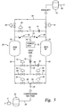
- Figure 3 is a schematic view of a two bed pressure swing adsorption system for generating a nitrogen rich gas;
- Figure 4 is a schematic view of a surface equipment installation including coiled tubing for delivering the inert gas to the area of the well to be cleaned out;
- Figure 5 is a schematic view of a wellbore showing an area of the well inhibited by the accumulation of sand in production tubing; and
- Figure 6 is a schematic view of the well of Figure 5 shown during well clean out using coiled tubing.
- The present invention is directed to the on-site, non-cryogenic production of an inert gas, typically a nitrogen rich gas and its delivery in the cleaning out of oil and/or gas or geothermal wells. As used herein the term "nitrogen rich gas" shall refer to a gas containing predominantly nitrogen gas and no more than 10% oxygen gas by volume. The nitrogen rich gas is produced from air by a number of different methods including membrane separation, pressure swing adsorption, vacuum swing adsorption and fuel cells. The methods of production are described in U.S. Patent No. 5,388,650 to Michael.
- Referring to Figure 1 there is shown an above ground installation for producing a nitrogen rich gas using membrane separation and for delivery of the nitrogen rich gas to the drilling region. A
feed air compressor 2 includes anintake port 4 for receiving ambient air and acompressor 6 for pressurising the air to a suitable pressure, typically in the range from about 100 to 350 psig (690 to 2400 kN). The compressed air is sent through aconduit 8 to an air separation membrane system shown generally bynumeral 10. The membrane is composed of bundles of hollow fibre, semi-permeable membranes which are assembled parallel to a central core tube. The bundle is placed into an outer case to form an air separation module. The air is divided into two streams; a nitrogen rich stream and a stream rich in oxygen and water vapour. - When the compressed air is introduced to the feed side of the membrane fibres, the air travels down the bore of the hollow permeable fibres. Oxygen, water vapour and other "fast gases" pass through to the outside of the fibres. The oxygen-rich gas stream then flows through the fibre bundle to the periphery of the outer case of the separator system where it is discharged as a by-product. While all but a small fraction of the oxygen passes through the membrane material to the exterior of the hollow fibres, most of the nitrogen present in the feed air is contained within the hollow fibre membrane. As a result, the nitrogen rich gas is effectively separated from the feed air and exits the
membrane system 10 via aconduit 12 for entry into anoptional booster compressor 14. - The
booster compressor 14 is employed to elevate the pressure of the nitrogen rich gas. The pressure of the gas obtained from the airseparation membrane system 10 is from about 100 to 200 psig (690 to 1400 kN). Thebooster compressor 14 is capable of raising the pressure of the nitrogen rich gas up to or exceeding 4500 psig (31×106 N) and even as high as about 10,000 psig (69×106 N), but typically in the range of from about 1,000 to 2,000 psig (6.9×10⁶ to 14×106 N). The highly compressed nitrogen rich gas leaves thebooster compressor 14 via aconduit 16 and is sent to asurface equipment installation 18 of the drilling operation as explained in detail hereinafter. - The nitrogen rich gas may also be produced by a pressure swing adsorption system in accordance with the present invention. Referring to Figures 2 and 3, there is disclosed a pressure
swing adsorption unit 20 having two beds "A" and "B". It should be understood, however, that the present invention is applicable to pressure swing adsorption units having an alternate construction such as a greater number of beds. Referring to Figure 3, air from a source (not shown) is fed to acompressor 6 to raise the pressure of the air, to accumulate compressed air during the non-production phase and to output compressed air during peak loading of the beds. The compressed air is fed to astorage vessel 22. The compressed air is then fed via theconduit outlet 28 leading to bed A and anoutlet 30, leading to bed B. Eachoutlet respective valves valve 32 is opened, allowing the compressed air to reach bed A,valve 34 remains closed so that bed B may undergo regeneration during the depressurisation phase of the pressureswing adsorption unit 20. - The compressed air enters the bed A through the
open valve 32 via aconduit 36. The bed A contains at least one adsorption material capable of preferentially adsorbing oxygen and other waste gases. The preferred adsorbents are selected from molecular sieves and silica gel. As a result, substantially pure nitrogen passes out of the bed A through aconduit 38, avalve 40 and into anitrogen storage vessel 42 via aproduct line 44 for passage via aconduit 82 to anoptional booster compressor 14, like the one shown in Figure 1. - While bed A is producing nitrogen gas, bed B is at atmospheric pressure. Upon completion of the nitrogen production cycle in bed A, the system undergoes equalisation to raise the pressure in bed B to an intermediate pressure. This is accomplished by closing the
nitrogen product valves air intake valves conduit 38,valve 50, aconduit 52,restrictive orifice 54, through aconduit 56 and into the top of the bed B. In addition, pressurised gas is passed from the bottom of the bed A via theconduit 36, avalve 58, aconduit 60, arestrictive orifice 62 and aconduit 64 into the bottom of bed B. - Once equalisation is completed so that bed A and B are at similar pressures, bed A undergoes regeneration by depressurising to atmospheric pressure to remove the oxygen enriched waste gases. This is accomplished by closing the
equalisation valves regeneration valve 66 for the bed A. The waste gas is then vented to the atmosphere through aconduit 68 and arestrictive orifice 70. As a consequence, the bed A is regenerated. Further cleansing of the bed A may be made by passing a purge gas, such as substantially pure nitrogen gas, from asource 72, throughconduits valve 78 and into bed A via theline 38. When the bed B is further cleansed, the purge gas passes through theconduits valve 80 and theconduit 56. After purging, the adsorbents are ready for adsorbing waste gases in a new nitrogen production cycle. - Since the pressure in bed B has been raised to an intermediate pressure, it is ready to receive compressed air. The compressed air is provided through the
valve 34 and theconduit 64. It may be necessary, in order to get sufficient compressed air to quickly load bed B up to operating pressure, for the compressed air feed generated by thecompressor 6 to be supplemented by compressed air already stored in thestorage vessel 22. Once bed B has been loaded, thevalve 46 is opened, allowing product gas to enter theproduct line 44 via theconduit 56 from which it enters thestorage vessel 42. Adistribution conduit 82 extends from thestorage vessel 42 to provide a flow of nitrogen rich product gas to thebooster compressor 14 shown in Figure 1. After nitrogen production in bed B is completed, thevalve 46 is closed as is thevalve 34 to stop the compressed air feed. The equalisation circuit is activated by openingvalves conduits valve 86 to the atmosphere via theconduit 68 andrestrictive orifice 70. - Thereafter, compressed air from the
compressor 6 and thestorage vessel 22 is fed to bed A through thevalve 32 via theconduit 36 to raise bed A to the desired operating pressure thereby commencing the nitrogen production cycle from bed A which passes into thebooster compressor 14. The nitrogen rich gas, after compression up to as high as 10,000 psig (69×106 N) in thebooster compressor 14, is sent to surface equipment installation shown in Figure 4, where it is used in the cleaning out of the well shown in Figure 5. - Referring to Figure 4, the high pressure nitrogen rich gas is delivered to the wellbore from a
source 120 through coiledtubing 100. The coiled tubing is charged with the gas at areel 105 and extends through astripper assembly 110. The flow rate of the nitrogen rich gas is typically measured by an orifice meter and is sent through an adjustable choke and a pressure shut off valve (not shown) before entering the wellbore. Foam can be added to the gas if it is required for downhole circulation. The foam is used to assist in well stimulation or removal of the sand, scale or other matter inhibiting the production of the well. The surface installation may optionally include an injector manifold for injecting chemicals, such as surfactants and special foaming agents, into the nitrogen rich gas feed stream to help dissolve and carry away particulate matter or to provide a low density, low velocity circulation medium of stiff and stable foam chemicals to cause minimum disturbance to unstable or unconsolidated formations. - Figure 5 is a section view of a
cased wellbore 200 withproduction tubing 202 extending to a location adjacent casingperforations 205. Anannular area 216 is isolated by upper andlower packing members production tubing 202 through aperforated screen member 215. In the preferred embodiment,annular area 216 is packed with gravel to encourage migration of production fluid from the surrounding formation into the wellbore. As illustrated, sand (shown as 220) has migrated through theperforated screen member 215 into the interior ofproduction tubing 202 and inhibited production of the well. - Figure 6 illustrates one embodiment of the cleaning out method of the present invention in progress. Coiled tubing 100 (see also Figure 4) has been inserted into the
production tubing 202 to provide a pathway for the flow of pressurised nitrogen rich gas (shown as bubbles 230) from the surface of the well to the area of the well to be cleaned out. As the lower end of the coiledtubing 100 breaches the area of sand in theproduction tubing 202, gas is injected into the well via the coiled tubing. Anannular area 231 formed between thecoiled tubing 100 and theproduction tubing 202 provides a pathway for the return nitrogen rich gas and with it, particulate matter, like sand, to the surface of the well where it is collected and disposed of The coiledtubing 100 is typically pumped up and down in the area of particulate matter, in order to agitate the material and to facilitate its removal during the clean out. - In operation, the nitrogen rich gas produced by the air
separation membrane system 10 or the pressureswing adsorption unit 20 or other non-cryogenic system typically has a nitrogen content of at least about 85% by volume, preferably at least about 95% by volume, and an oxygen content of no more than 10% by volume, preferably less than about 5% by volume. The nitrogen rich gas is sent to abooster compressor 14 where the pressure is raised to as high as 10,000 psig (69×106 N) or more, typically in the range of about 1,000 to 2,000 psig (6.9×10⁶ to 14×106 N). The pressurised nitrogen rich gas is sent to the surface equipment shown in Figure 4 where it is monitored and metered into the wellbore through the pathway within the coiledtubing 100. - Because the nitrogen rich gas is under pressure, it swirls around the area to be cleaned out with sufficient force and velocity to carry the particulates upward into the pathway created within
annular area 231. The particulate-containing stream then exits the production tubing at the surface of the well where it is carried to a blooey line and eventually discarded into a collection facility, typically at a location remote from the actual well site. - A typical well cleanout is performed in a series of sequential steps. First, nitrogen is produced on site using any of the foregoing methods. Second, coiled tubing is placed in the well and lowered a predetermined distance to the area of the well where production is inhibited. Third, the gas, as well as foam is introduced simultaneously into the coiled tubing. Fourth, the coiled tubing is pumped up and down in the well to agitate the substance inhibiting production and encourage its removal. Fifth, the return of material at the surface is measured and monitored. Finally, when the material carried by the return gas has diminished to an acceptable level, the cleanout operation is discontinued. The flow rate of nitrogen rich gas to the drilling region of an oil and/or gas well or a geothermal well can vary over a wide range depending on the size of the downhole, the depth of the well, the rate of production and, the size of the production tubing.
- A typical cleaning out operation will require the production of from 1,500 to 3,000 standard cubic feet per minute (scfm) (700 to 1400 litres per second) of nitrogen gas from an air separation system which can be anyone of a number of conventional systems including an air membrane separation system or a pressure swing adsorption system. The purity of the nitrogen gas may vary, but is nominally set at no more than about 5% by volume of oxygen. The resulting nitrogen rich gas is then pressurised up to a pressure of from about 1,500 to 2,000 psig (10×106 to 14×106 N) before being passed to the area of the well to be cleaned out.
- A cleaning out operation will take about two days, although very clogged wells may require more time. The nitrogen rich gas delivery system is designed for continuous operation and all of the nitrogen rich gas is generated on-site without the need for external nitrogen replenishment required for cryogenically produced liquid nitrogen delivery systems.
- In addition to well clean out, the on site production of non-cryogenic nitrogen may provide a source of gas for servicing or stimulating a well or for pressure testing downhole devices like packers.
- It will be understood that variations from the above described embodiments will still fall within the scope of the invention, which is defined by the following claims.
Claims (15)
- A method for cleaning out an oil and/or gas or geothermal well in which production is inhibited, comprising:(a) removing at least a substantial portion of the oxygen contained within a feed stream of air (4) at the site of said well (200) to produce a pressurised nitrogen rich gas (230) and an oxygen enriched waste gas; and(b) delivering the nitrogen rich gas to the area of the well to be cleaned out, whereby material (220) inhibiting the production of the well is relocated;characterised in that the gas (230) is delivered to the area in coiled tubing (100).
- A method as claimed in claim 1, wherein the material (220) is removed from the well (200).
- A method as claimed in claim 1 or 2, wherein step (a) comprises passing a feed stream of air through a membrane (10) which preferentially separates nitrogen gas from the other gaseous components of air.
- A method as claimed in claim 1 or 2, wherein the step of removing at least a substantial portion of oxygen comprises passing a feed stream of air through a pressure swing adsorption unit (20) containing an absorbent which preferentially adsorbs oxygen and other gases contained within the feed stream of air to form the nitrogen rich gas.
- A method as claimed in any preceding claim, wherein the nitrogen rich gas contains at least 85 percent volume of nitrogen.
- A method as claimed in any preceding claim, wherein the nitrogen rich gas contains at least 95 percent volume of nitrogen.
- A method as claimed in any preceding claim, further comprising raising the pressure of the nitrogen rich gas to at least 1,000 psig (6.9×10⁶ N) before delivering the nitrogen rich gas to the area of the well to be cleaned out.
- A method as claimed in claim7, wherein the pressure of the nitrogen rich gas is raised to about 1,000 to 2,000 psig (6.9×10⁶ to 14×106 N).
- A method as claimed in any preceding claim, further comprising varying the oxygen content of the nitrogen rich gas prior to the delivery of the nitrogen rich gas to the area of the well to be cleaned out.
- A method as claimed in any preceding claim, whereby the coiled tubing (100) is delivered to an area inside production tubing (202).
- A method as claimed in claim 10, whereby the material is circulated towards the surface of the well through an annulus (231) between the coiled tubing (100) and the production tubing (202).
- A method as claimed in claim 10 or 11, wherein the method includes the step of moving the lower end of the coiled tubing (100) up and downwards in the production tubing (202) in order to agitate particulate matter (220) in the production tubing.
- A method as claimed in any preceding claim, wherein the nitrogen rich gas is delivered along with an additive to the area to be cleaned out.
- A method as claimed in claim 13, wherein the additive is a surfactant.
- A method as claimed in claim 13, wherein the nitrogen rich gas is delivered with foam.
Applications Claiming Priority (3)
| Application Number | Priority Date | Filing Date | Title |
|---|---|---|---|
| US642447 | 2000-08-18 | ||
| US09/642,447 US6494262B1 (en) | 2000-08-18 | 2000-08-18 | Non-cryogenic production of nitrogen for on-site injection in well clean out |
| PCT/GB2001/003672 WO2002016009A2 (en) | 2000-08-18 | 2001-08-16 | Non-cryogenic production of nitrogen for on-site injection in well clean out |
Publications (2)
| Publication Number | Publication Date |
|---|---|
| EP1311336A2 EP1311336A2 (en) | 2003-05-21 |
| EP1311336B1 true EP1311336B1 (en) | 2006-10-04 |
Family
ID=24576593
Family Applications (1)
| Application Number | Title | Priority Date | Filing Date |
|---|---|---|---|
| EP01958218A Expired - Lifetime EP1311336B1 (en) | 2000-08-18 | 2001-08-16 | Production of nitrogen for on-site injection in well clean out |
Country Status (6)
| Country | Link |
|---|---|
| US (2) | US6494262B1 (en) |
| EP (1) | EP1311336B1 (en) |
| AU (1) | AU2001279945A1 (en) |
| CA (1) | CA2416560C (en) |
| DE (1) | DE60123633D1 (en) |
| WO (1) | WO2002016009A2 (en) |
Families Citing this family (13)
| Publication number | Priority date | Publication date | Assignee | Title |
|---|---|---|---|---|
| US6494262B1 (en) | 2000-08-18 | 2002-12-17 | Weatherford/Lamb, Inc. | Non-cryogenic production of nitrogen for on-site injection in well clean out |
| BRPI0210416B1 (en) * | 2001-06-15 | 2017-04-25 | Statoil Asa | method of recovering oil from a natural oil reservoir, method of modifying an enhanced oil recovery process, method of modifying an enhanced oil recovery facility, facility for enhanced oil recovery, modified facility for enhanced recovery of oil |
| CA2450994C (en) * | 2003-11-27 | 2010-08-10 | Weatherford Canada Ltd. | Method and apparatus to control the rate of flow of a fluid through a conduit |
| US7468173B2 (en) * | 2004-02-25 | 2008-12-23 | Sunstone Corporation | Method for producing nitrogen to use in under balanced drilling, secondary recovery production operations and pipeline maintenance |
| US20090140444A1 (en) * | 2007-11-29 | 2009-06-04 | Total Separation Solutions, Llc | Compressed gas system useful for producing light weight drilling fluids |
| US8025108B2 (en) * | 2008-09-04 | 2011-09-27 | New Era Petroleum, Llc. | Subterranean methods of processing hydrocarbon fluid-containing deposits and hydrocarbon recovery arrangements for recovering hydrocarbon-containing fluid from hydrocarbon-containing deposits |
| CA2700947C (en) * | 2009-04-17 | 2014-03-18 | Darrell S. Kosakewich | Method and apparatus for freeze-thaw well stimulation using orificed refrigeration tubing |
| US8733443B2 (en) * | 2010-12-21 | 2014-05-27 | Saudi Arabian Oil Company | Inducing flowback of damaging mud-induced materials and debris to improve acid stimulation of long horizontal injection wells in tight carbonate formations |
| US9243485B2 (en) | 2013-02-05 | 2016-01-26 | Triple D Technologies, Inc. | System and method to initiate permeability in bore holes without perforating tools |
| US9309741B2 (en) | 2013-02-08 | 2016-04-12 | Triple D Technologies, Inc. | System and method for temporarily sealing a bore hole |
| CN105399063B (en) * | 2015-12-08 | 2017-08-25 | 山东恒业石油新技术应用有限公司 | Combined high-voltage nitrogen purification equipment |
| US20180361311A1 (en) * | 2015-12-09 | 2018-12-20 | Generon Igs, Inc. | Membrane-based system for generating high-purity nitrogen |
| US11939850B2 (en) | 2022-01-07 | 2024-03-26 | Saudi Arabian Oil Company | Apparatus for TCA bleed off and well start-up |
Family Cites Families (12)
| Publication number | Priority date | Publication date | Assignee | Title |
|---|---|---|---|---|
| US3583483A (en) * | 1969-07-09 | 1971-06-08 | Chevron Res | Method for using foam in wells |
| US3662828A (en) * | 1970-09-11 | 1972-05-16 | Chevron Res | Through tubing well cleanout method using foam |
| US4457375A (en) * | 1980-08-27 | 1984-07-03 | Cummins Mark A | Foam generating device for wells |
| GB2186682B (en) | 1986-01-13 | 1990-05-16 | Boc Group Plc | Gas supply apparatus |
| US5125455A (en) | 1991-01-08 | 1992-06-30 | Halliburton Services | Primary cementing |
| US5388650B1 (en) * | 1993-06-14 | 1997-09-16 | Mg Nitrogen Services Inc | Non-cryogenic production of nitrogen for on-site injection in downhole drilling |
| US5749422A (en) | 1993-06-14 | 1998-05-12 | Mg Nitrogen Services, Inc. | Non-cryogenic nitrogen for on-site downhole drilling and post drilling operations |
| US5663121A (en) * | 1993-12-23 | 1997-09-02 | Moody; Eugene I. | Method and apparatus for providing a stream of inert gases in underbalanced drilling of a well bore |
| US6234258B1 (en) * | 1999-03-08 | 2001-05-22 | Halliburton Energy Services, Inc. | Methods of separation of materials in an under-balanced drilling operation |
| US6269880B1 (en) * | 2000-01-27 | 2001-08-07 | Ronald J. Landry | System for removing solids from a well bore |
| US6527050B1 (en) * | 2000-07-31 | 2003-03-04 | David Sask | Method and apparatus for formation damage removal |
| US6494262B1 (en) | 2000-08-18 | 2002-12-17 | Weatherford/Lamb, Inc. | Non-cryogenic production of nitrogen for on-site injection in well clean out |
-
2000
- 2000-08-18 US US09/642,447 patent/US6494262B1/en not_active Expired - Lifetime
-
2001
- 2001-08-16 AU AU2001279945A patent/AU2001279945A1/en not_active Abandoned
- 2001-08-16 DE DE60123633T patent/DE60123633D1/en not_active Expired - Lifetime
- 2001-08-16 EP EP01958218A patent/EP1311336B1/en not_active Expired - Lifetime
- 2001-08-16 CA CA002416560A patent/CA2416560C/en not_active Expired - Lifetime
- 2001-08-16 WO PCT/GB2001/003672 patent/WO2002016009A2/en not_active Ceased
-
2002
- 2002-12-10 US US10/315,734 patent/US6929068B2/en not_active Expired - Lifetime
Also Published As
| Publication number | Publication date |
|---|---|
| AU2001279945A1 (en) | 2002-03-04 |
| CA2416560C (en) | 2006-01-31 |
| US6494262B1 (en) | 2002-12-17 |
| CA2416560A1 (en) | 2002-02-28 |
| US6929068B2 (en) | 2005-08-16 |
| WO2002016009A2 (en) | 2002-02-28 |
| US20030075320A1 (en) | 2003-04-24 |
| WO2002016009A3 (en) | 2002-08-01 |
| EP1311336A2 (en) | 2003-05-21 |
| DE60123633D1 (en) | 2006-11-16 |
Similar Documents
| Publication | Publication Date | Title |
|---|---|---|
| US5388650A (en) | Non-cryogenic production of nitrogen for on-site injection in downhole drilling | |
| US6494262B1 (en) | Non-cryogenic production of nitrogen for on-site injection in well clean out | |
| CN1051354C (en) | Method for recovery of coal bed methane with reduced inert gas fraction in produced gas | |
| US7763099B2 (en) | Downhole separation of carbon dioxide from natural gas produced from natural gas reservoirs | |
| US5992521A (en) | Method and system for increasing oil production from an oil well producing a mixture of oil and gas | |
| US5794697A (en) | Method for increasing oil production from an oil well producing a mixture of oil and gas | |
| RU2320864C2 (en) | Well treatment method and system | |
| US5860476A (en) | Method and apparatus for separating a well stream | |
| US20030047310A1 (en) | Downhole gas separation method and system | |
| US6772837B2 (en) | Screen assembly having diverter members and method for progressively treating an interval of a welibore | |
| CA2489968C (en) | Method for the circulation of gas when drilling or working a well | |
| JP3786987B2 (en) | Pollutant removal method and apparatus | |
| EA015158B1 (en) | Method of fracturing a coalbed gas reservoir | |
| CN114985436B (en) | Gas-liquid multi-medium pumping and injecting integrated well pipe device | |
| US5749422A (en) | Non-cryogenic nitrogen for on-site downhole drilling and post drilling operations | |
| US20030051874A1 (en) | Downhole membrane separation system with sweep gas | |
| US20170067316A1 (en) | Method of gas, oil and mineral production using a clean processing system and method | |
| US20030079876A1 (en) | Method and system for regeneration of a membrane used to separate fluids in a wellbore | |
| US6053249A (en) | Method and apparatus for injecting gas into a subterranean formation | |
| US5669445A (en) | Well gravel pack formation method | |
| EP1582504A1 (en) | Method and system for producing inert gas from combustion by-products | |
| RU2015309C1 (en) | Method for making well strainer | |
| EP1423181B1 (en) | Downhole gas separation method | |
| US3397743A (en) | Removal of foreign element from a well | |
| WO2017175206A1 (en) | Process for the removal in the well of the acid components from hydrocarbons and related well |
Legal Events
| Date | Code | Title | Description |
|---|---|---|---|
| PUAI | Public reference made under article 153(3) epc to a published international application that has entered the european phase |
Free format text: ORIGINAL CODE: 0009012 |
|
| 17P | Request for examination filed |
Effective date: 20030220 |
|
| AK | Designated contracting states |
Designated state(s): AT BE CH CY DE DK ES FI FR GB GR IE IT LI LU MC NL PT SE TR |
|
| AX | Request for extension of the european patent |
Extension state: AL LT LV MK RO SI |
|
| 17Q | First examination report despatched |
Effective date: 20030919 |
|
| RBV | Designated contracting states (corrected) |
Designated state(s): AT BE CH CY DE FR GB LI |
|
| GRAP | Despatch of communication of intention to grant a patent |
Free format text: ORIGINAL CODE: EPIDOSNIGR1 |
|
| RTI1 | Title (correction) |
Free format text: PRODUCTION OF NITROGEN FOR ON-SITE INJECTION IN WELL CLEAN OUT |
|
| GRAS | Grant fee paid |
Free format text: ORIGINAL CODE: EPIDOSNIGR3 |
|
| GRAA | (expected) grant |
Free format text: ORIGINAL CODE: 0009210 |
|
| AK | Designated contracting states |
Kind code of ref document: B1 Designated state(s): DE FR GB NL |
|
| PG25 | Lapsed in a contracting state [announced via postgrant information from national office to epo] |
Ref country code: NL Free format text: LAPSE BECAUSE OF FAILURE TO SUBMIT A TRANSLATION OF THE DESCRIPTION OR TO PAY THE FEE WITHIN THE PRESCRIBED TIME-LIMIT Effective date: 20061004 |
|
| RBV | Designated contracting states (corrected) |
Designated state(s): DE FR GB NL |
|
| REG | Reference to a national code |
Ref country code: GB Ref legal event code: FG4D |
|
| REF | Corresponds to: |
Ref document number: 60123633 Country of ref document: DE Date of ref document: 20061116 Kind code of ref document: P |
|
| PG25 | Lapsed in a contracting state [announced via postgrant information from national office to epo] |
Ref country code: DE Free format text: LAPSE BECAUSE OF FAILURE TO SUBMIT A TRANSLATION OF THE DESCRIPTION OR TO PAY THE FEE WITHIN THE PRESCRIBED TIME-LIMIT Effective date: 20070105 |
|
| NLV1 | Nl: lapsed or annulled due to failure to fulfill the requirements of art. 29p and 29m of the patents act | ||
| EN | Fr: translation not filed | ||
| PLBE | No opposition filed within time limit |
Free format text: ORIGINAL CODE: 0009261 |
|
| STAA | Information on the status of an ep patent application or granted ep patent |
Free format text: STATUS: NO OPPOSITION FILED WITHIN TIME LIMIT |
|
| 26N | No opposition filed |
Effective date: 20070705 |
|
| PG25 | Lapsed in a contracting state [announced via postgrant information from national office to epo] |
Ref country code: FR Free format text: LAPSE BECAUSE OF FAILURE TO SUBMIT A TRANSLATION OF THE DESCRIPTION OR TO PAY THE FEE WITHIN THE PRESCRIBED TIME-LIMIT Effective date: 20070525 |
|
| PG25 | Lapsed in a contracting state [announced via postgrant information from national office to epo] |
Ref country code: FR Free format text: LAPSE BECAUSE OF FAILURE TO SUBMIT A TRANSLATION OF THE DESCRIPTION OR TO PAY THE FEE WITHIN THE PRESCRIBED TIME-LIMIT Effective date: 20061004 |
|
| REG | Reference to a national code |
Ref country code: GB Ref legal event code: 732E Free format text: REGISTERED BETWEEN 20151022 AND 20151028 |
|
| PGFP | Annual fee paid to national office [announced via postgrant information from national office to epo] |
Ref country code: GB Payment date: 20160810 Year of fee payment: 16 |
|
| GBPC | Gb: european patent ceased through non-payment of renewal fee |
Effective date: 20170816 |
|
| PG25 | Lapsed in a contracting state [announced via postgrant information from national office to epo] |
Ref country code: GB Free format text: LAPSE BECAUSE OF NON-PAYMENT OF DUE FEES Effective date: 20170816 |