EP1311168B1 - Method, system and shoe enabling the determination of fit from outside of the shoe - Google Patents
Method, system and shoe enabling the determination of fit from outside of the shoe Download PDFInfo
- Publication number
- EP1311168B1 EP1311168B1 EP01966070A EP01966070A EP1311168B1 EP 1311168 B1 EP1311168 B1 EP 1311168B1 EP 01966070 A EP01966070 A EP 01966070A EP 01966070 A EP01966070 A EP 01966070A EP 1311168 B1 EP1311168 B1 EP 1311168B1
- Authority
- EP
- European Patent Office
- Prior art keywords
- shoe
- reference mark
- foot
- outsole
- gauge
- Prior art date
- Legal status (The legal status is an assumption and is not a legal conclusion. Google has not performed a legal analysis and makes no representation as to the accuracy of the status listed.)
- Expired - Lifetime
Links
- 238000000034 method Methods 0.000 title claims description 17
- 210000002683 foot Anatomy 0.000 claims description 68
- 210000003371 toe Anatomy 0.000 claims description 22
- 230000000007 visual effect Effects 0.000 claims description 14
- 239000000853 adhesive Substances 0.000 claims description 10
- 230000001070 adhesive effect Effects 0.000 claims description 10
- 239000000758 substrate Substances 0.000 claims description 5
- 230000001681 protective effect Effects 0.000 claims description 2
- 210000003414 extremity Anatomy 0.000 claims 3
- 239000004033 plastic Substances 0.000 description 7
- 239000000463 material Substances 0.000 description 3
- 238000004040 coloring Methods 0.000 description 2
- 238000010276 construction Methods 0.000 description 2
- 239000010985 leather Substances 0.000 description 2
- 241000293001 Oxytropis besseyi Species 0.000 description 1
- 238000010521 absorption reaction Methods 0.000 description 1
- 238000005259 measurement Methods 0.000 description 1
Images


Classifications
-
- A—HUMAN NECESSITIES
- A43—FOOTWEAR
- A43D—MACHINES, TOOLS, EQUIPMENT OR METHODS FOR MANUFACTURING OR REPAIRING FOOTWEAR
- A43D1/00—Foot or last measuring devices; Measuring devices for shoe parts
-
- A—HUMAN NECESSITIES
- A43—FOOTWEAR
- A43B—CHARACTERISTIC FEATURES OF FOOTWEAR; PARTS OF FOOTWEAR
- A43B23/00—Uppers; Boot legs; Stiffeners; Other single parts of footwear
- A43B23/24—Ornamental buckles; Other ornaments for shoes without fastening function
-
- A—HUMAN NECESSITIES
- A43—FOOTWEAR
- A43B—CHARACTERISTIC FEATURES OF FOOTWEAR; PARTS OF FOOTWEAR
- A43B1/00—Footwear characterised by the material
- A43B1/0072—Footwear characterised by the material made at least partially of transparent or translucent materials
-
- A—HUMAN NECESSITIES
- A43—FOOTWEAR
- A43B—CHARACTERISTIC FEATURES OF FOOTWEAR; PARTS OF FOOTWEAR
- A43B3/00—Footwear characterised by the shape or the use
- A43B3/0036—Footwear characterised by the shape or the use characterised by a special shape or design
- A43B3/0078—Footwear characterised by the shape or the use characterised by a special shape or design provided with logos, letters, signatures or the like decoration
-
- A—HUMAN NECESSITIES
- A43—FOOTWEAR
- A43B—CHARACTERISTIC FEATURES OF FOOTWEAR; PARTS OF FOOTWEAR
- A43B3/00—Footwear characterised by the shape or the use
- A43B3/0036—Footwear characterised by the shape or the use characterised by a special shape or design
- A43B3/0078—Footwear characterised by the shape or the use characterised by a special shape or design provided with logos, letters, signatures or the like decoration
- A43B3/0089—Footwear characterised by the shape or the use characterised by a special shape or design provided with logos, letters, signatures or the like decoration with means to identify the size of the shoe
-
- A—HUMAN NECESSITIES
- A43—FOOTWEAR
- A43D—MACHINES, TOOLS, EQUIPMENT OR METHODS FOR MANUFACTURING OR REPAIRING FOOTWEAR
- A43D1/00—Foot or last measuring devices; Measuring devices for shoe parts
- A43D1/02—Foot-measuring devices
- A43D1/027—Shoe fit indicating devices
Definitions
- the invention relates to a method, system and shoe for determining the fit of a shoe from outside the shoe.
- shoes are known in the art. Some shoes known in the art provide means for determining whether they fit. However, none of the prior art provides a way to determine whether a shoe will fit from outside the shoe. For example, a person may be in a hurry and not want to take the time to try on a shoe. Also, room to try on a shoe may not be available where the shoe is sold. Also, a shoe may be sold where there is insufficient experienced staff to help a person choose the correct size. In addition, a person buying a shoe for a child may not be able to determine the room within the shoe for growth of a child's foot.
- U.S. Patent No. 5,014,041 to Rosen and U.S. Patent No. 5,084,988 to Berger disclose shoes that have transparent soles through to the interior of the shoe to show when a foot is outgrowing a shoe. These patents require that a person wear the shoe before being able to determine whether they fit. Additionally, Rosen and Berger suffer from the fact that over time the transparent soles may discolor and get scuffs so that a person could not look through them.
- U.S. Patent No. 2,464,571 to Gardner discloses a removable shoe-fit indicator which indicates the fit of the shoe on the child on an insole.
- a person must put coloring on the removable indicator which will color a childls toes or socks to indicate the fit of the shoe.
- the interior piece would make the process of making the shoe more expensive, and would impact the comfort of the shoe.
- the use of coloring makes Gardner messy and inconvenient.
- EP 0,662,287 which relates to a heel gauge 2 and at least one first reference and second reference toe marks on an outsole.
- US 4,931,773 relates to an insole with heel zone 48 and toe zone 56-58 and Ball Mark 52.
- FR 850,599 relates to a box or cover for shoes, which can contain a scale on the box, or shapes of shoes according to different sizes.
- US 2,109,780 further relates to an inner shoe with marks 17-20 and a transverse elongated strip 25 located on the inner shoe above the inner sole and which can further only be seen with X-Rays.
- US 2,029,553 shows shoe fitting index embedded in the shoe to be seen with X-Rays.
- GB 2,020,832 and FR 2,103,740 represent technological background.
- the principal object of the invention is to provide a shoe wherein a person can determine whether a shoe fits without trying it on.
- the present invention is a system including a shoe or a shoe with an outsole having a reference gauge at the proximal end of the outsole for placing the heel of a foot; and reference marks as defined in shoe claims 1 to 8; or system claims 9 to 13.
- the reference gauge is substantially u-shaped to correspond to a heel of a foot.
- the reference gauge is substantially an end line.
- the outsole also has a second reference mark distal from the first reference mark corresponding to a clearance distance within the shoe.
- the outsole further comprises an outline corresponding with the overall shape within the shoe.
- the reference gauge is permanently affixed to the outsole.
- the first reference mark is permanently affixed to the outsole.
- the second reference mark is permanently affixed to the outsole.
- the third reference mark is permanently affixed to the outsole.
- the fourth reference mark is permanently affixed to the outsole.
- the outline is permanently affixed to the outsole.
- the reference gauge is temporarily affixed to the outsole.
- the first reference mark is temporarily affixed to the outsole.
- the second reference mark is temporarily affixed to the outsole.
- the third reference mark is temporarily affixed to the outsole.
- the fourth reference mark is temporarily affixed to the outsole.
- the outline is temporarily affixed to the outsole.
- the invention is a method for determining the fit of a shoe from outside the shoe as defined in method claims 14 to 18.
- the reference gauge corresponds to the location of a person's heel inside the shoe.
- the reference gauge is substantially u-shaped to correspond to a heel of a foot.
- the reference gauge is substantially an end line.
- the outsole further comprises a second reference mark distal from the first reference mark corresponding to the clearance distance within the shoe.
- the outsole further comprises an outline corresponding to the overall shape within the shoe, and the method further comprises the step of comparing the overall shape of the foot with the outline.
- the reference gauge is permanently affixed to the outsole.
- the first reference mark is permanently affixed to the outsole.
- the second reference mark is permanently affixed to the outsole.
- the third reference mark is permanently affixed to the outsole.
- the fourth reference mark is permanently affixed to the outsole.
- the outline is permanently affixed to the outsole.
- the reference gauge is temporarily affixed to the outsole.
- the first reference mark is temporarily affixed to the outsole.
- the second reference mark is temporarily affixed to the outsole.
- the third reference mark is temporarily affixed to the outsole.
- the fourth reference mark is temporarily affixed to the outsole.
- the outline is temporarily affixed to the outsole.
- the invention relates to a shoe fit guide as defined in claims 19 to 29 and to a system for determining the fit of a shoe using a detachable decal as defined in claims 30 to 32.
- the above described features may be incorporated onto a decal which is removably or peelably attached to a substrate.
- a shoe retailer or manufacturer can then apply a decal corresponding to a respective shoe size to one or both of the shoe outsoles, depending on whether the decal is for a left or right shoe. Consumers can then match a foot to the outsole with the decal applied to determine if the shoe size is proper without having to actually try on the shoe first.
- the features are incorporated on a tag which acts as a visual shoe fit guide that can come with the shoe in a shoe box and be preferably attached to one of the shoes so that when the shoe is removed from the shoe box in a retail store, the tag is available for a quick reference check to determine if the shoe size is correct.
- the tag can be printed on both sides wherein one side will correspond to a left foot and the opposite side will correspondent to the right foot.
- shoe size gauges may be available in some stores for consumers to use, but in most cases, they are not. Even when made available, they are often difficult to use due to the complexity of reference marks indicating both width and sizes for each foot. When read properly, they are accurate but more often than not in discount stores, consumers generally have to fit themselves. Therefore, the present invention provides a useful and simple means for checking proper shoe size without having to wait for a sales person to attend to the consumer.
- the shoe 10 used to protect a foot 12, may be made of any of the materials known in the art, including leather and rubber.
- the outside of the shoe 10 comprises an outsole 14 or bottom.
- the outsole 14 also can be made of many materials known in the art, including rubber and leather.
- the outsole 14 of the shoe 10 includes a reference gauge 16 at the proximal end 18 of the outsole 14 for the placing of the heel 20 of the foot 12 as generally shown in Figs. 1 and 2 .
- the reference gauge 16 is shaped to correspond with a person's heel 20.
- the reference gauge 16 may comprise of one or more marks and may be substantially u-shaped or substantially an end line or comprise of another shape or other shapes.
- the preferred embodiment is a substantially u-shaped reference gauge 16, as shown in Figs. 1 and 2 .
- the reference gauge 16 may be permanently or temporarily affixed to the outsole 14.
- the reference gauge 16 may be placed on the outsole 14 by being molded into, painted, printed or inscribed into the outsole 14.
- the reference gauge 16 may be printed on plastic or paper with an adhesive backing and attached to the outsole 14. Other means of placing the reference gauge 16 on the outsole 14 are known in the art.
- the location of the reference gauge 16 corresponds with heel 20 placement inside the shoe 10.
- the outsole 14 comprises a first reference mark 22 at the distal end 24 of the outsole, corresponding to where the toes of the foot 12 should extend when the heel 20 is placed on the reference gauge 16 to ensure a proper fit of the shoe 10 on the foot 12.
- the first reference mark 22 may be a bar, a line, a series of lines or an area indicating a range within which the toes of the foot 12 may extend from the reference gauge 16 so that the shoe 10 would still fit. Additional means for providing a first reference mark 22 corresponding to where the toes should align for proper fit are also known in the art.
- the outsole 14 may further comprise a second reference mark 26.
- the second reference mark corresponds with the room left within the shoe 10 from the distal end of the first reference mark 22.
- the second reference mark 26 thus may operate as a warning bar indicating the maximum recommended allowance for toe room and growth.
- the second reference mark may measure a clearance distance for the foot 12 distally up to the tip 28 of the inside of the shoe 10, or vamp. However, the measured clearance distance may also be to the end of the sole part inside the shoe 10, or any other known point for measuring clearance distance for the foot 12.
- the first reference mark 22 may be placed permanently or temporarily on the outsole 14.
- the first reference mark 22 may be molded into, painted, printed or inscribed into the outsole 14.
- the first reference mark 22 may be printed on plastic or paper with an adhesive backing and attached to the outsole 14.
- Other means of placing the first reference mark 22 on the outsole 14, permanently and temporarily, are known in the art.
- the second reference mark 26 may be placed permanently or temporarily on the outsole 14.
- the second reference mark 26 may be molded into, painted, printed or inscribed into the outsole 14.
- the second reference mark 26 may be printed on plastic or paper with an adhesive backing and attached to the outsole 14. Other means of placing the second reference mark 26 on the outsole 14, permanently and temporarily, are known in the art.
- the outsole may comprise a third reference mark 30 corresponding with the width of the inside of the shoe 10.
- Figures 1 - 3 show the third reference mark 30 as intermediate between the reference gauge 16 and the first reference mark 22.
- Figures 1 - 3 show the third reference mark 30 as two marks.
- the third reference mark 30 may also be indicated by a single area, outline or other means for describing the width within the shoe on the outsole 14.
- the third reference mark 30 may be placed permanently or temporarily on the outsole 14.
- the third reference mark 30 may be molded into, painted, printed or inscribed into the outsole 14.
- the third reference mark 30 may be printed on plastic or paper with an adhesive backing and attached to the outsole 14.
- Other means of placing the third reference mark 30 on the outsole 14, permanently and temporarily, are known in the art.
- the outsole 14 may also comprise a fourth reference mark 32 intermediate to the reference gauge 16 and the first reference mark 22.
- the fourth reference mark 32 corresponds to where the ball of the foot 12 should align when the heel 20 is in the reference gauge 16 to ensure a proper measurement of the toes against the first reference mark 22.
- the fourth reference mark 32 may be an outline or an area indicating the proper placement for the ball of the foot 12.
- the fourth reference mark 32 may also be molded into, painted, printed or inscribed into the outsole 14.
- the fourth reference mark 32 may also be printed on plastic or paper with an adhesive backing and attached to the outsole 14. Other means of placing the fourth reference mark 32 on the outsole 14, permanently and temporarily, are known in the art.
- the outsole 14 may also comprise an outline 34 corresponding with the overall shape within the shoe 10.
- the outline 34 may also be molded into, painted, printed or inscribed into the outsole 14.
- the outline 34 may be printed on plastic or paper with an adhesive backing and attached to the outsole 14. Additional means of placing the outline 34 on the outsole 14, permanently and temporarily, are known in the art.
- the current invention contemplates that the reference gauge 16, first reference mark 22, second reference mark 26, third reference mark 30, fourth reference mark 32 and the outline 34 may be placed on the outsole 14 in any combination within the scope of the claims. Furthermore, the means for placing the applicable reference gauge 16, first reference mark 22, second reference mark 26, third reference mark 30, fourth reference mark 32 or outline 34, permanently or temporarily, may be different from one another or the same.
- a person seeks to buy a shoe 10 incorporating the present invention.
- the person places a foot 12 on the outsole 14 of the shoe, aligning the heel 20 with the reference gauge 16. If the outsole 14 is so equipped, the person may place the ball of the foot 12 where indicated on the outsole 14 by the second reference mark 26. After the person's foot 12 is properly aligned, the person may quickly determine whether that person's toes extend past an area described by the first reference mark 22. If the toes extend beyond the area described by the first reference mark 22, the shoe 10 will be too small. Similarly, if the person's toes do not extend to the area described by the first reference mark 22 the shoe 10 will be too large.
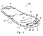
- gauge 16 and applicable reference marks are printed on a thin plastic such as a decal, as generally depicted as 100 in Fig. 4 , which is peeled from a substrate 36 to which the decal 38 is removably attached, and subsequently attached to the outsole 14 with the detachable adhesive 52 applied to one side of the decal 38, the person may remove the decal 38 after purchasing the shoes if the person wishes.
- Fig. 4 depicts each of the aforementioned features that may be incorporated on the outsole 14 wherein the features are arranged between the proximal end 44 of the decal 38 and the distal end 46 of the decal 38.
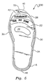
- Fig. 5 depicts another embodiment which is generally depicted as 200.
- This embodiment is a tag or hang tag 40, wherein each or any combination of the aforementioned features are printed on at least one side of the tag 40 and arranged between the tag's proximal end 48 and its distal end 60.
- the tag is preferably formed in the shape of a shoe outsole .14, although it need not be.
- the imprinted is done on both sides of the tag 40 so that one side represents a left foot and the opposite side represents a right foot. Both sides are not shown in the drawings as Fig. 5 which currently depicts a right foot, when flipped over, would represent a left foot.
- the tag 40 may be inserted in a shoe box and represent a size corresponding to the size of the shoes included in the shoe box. Preferably so the tag 40 is not lost, hole 42 should be included so the tag can be temporarily attached to one of the shoes such as an eyelet or a shoestring. After the shoes are purchased, the consumer can then remove the tag 40 prior to use of the shoes. Of course, if the manufacturer desires, a separate tag 40 may be attached to each of a left and right shoe, wherein the tag 40 representing a left shoe is attached to the left shoe and a tag 40 representing a right shoe is attached to the right shoe.
- the tag 40 is typically made from paper stock material similar to that used for most tags attached on clothing and accessories.
- the present invention satisfies a long felt need to provide a device which is easy to use.
- the invention is especially convenient for people that want to purchase shoes without trying them on, and for people buying shoes for children.
- the invention is especially helpful in self-service locations or locations with insufficient sales staff to help a person choose the correct size.
- the invention will be especially useful for a person seeking to buy a shoe for a child where the child's shoe size is not known, and where a person seeks to monitor a child's growth as related to the child's shoe size.
Landscapes
- Life Sciences & Earth Sciences (AREA)
- Biophysics (AREA)
- Footwear And Its Accessory, Manufacturing Method And Apparatuses (AREA)
Description
- The invention relates to a method, system and shoe for determining the fit of a shoe from outside the shoe.
- Many types of shoes are known in the art. Some shoes known in the art provide means for determining whether they fit. However, none of the prior art provides a way to determine whether a shoe will fit from outside the shoe. For example, a person may be in a hurry and not want to take the time to try on a shoe. Also, room to try on a shoe may not be available where the shoe is sold. Also, a shoe may be sold where there is insufficient experienced staff to help a person choose the correct size. In addition, a person buying a shoe for a child may not be able to determine the room within the shoe for growth of a child's foot.
- For example,
U.S. Patent No. 5,014,041 to Rosen andU.S. Patent No. 5,084,988 to Berger disclose shoes that have transparent soles through to the interior of the shoe to show when a foot is outgrowing a shoe. These patents require that a person wear the shoe before being able to determine whether they fit. Additionally, Rosen and Berger suffer from the fact that over time the transparent soles may discolor and get scuffs so that a person could not look through them. - The use of removable insoles or socks with printed length areas which are removable from the inside of the shoe are known in the industry. In addition,
U.S. Patent No. 2,464,571 to Gardner discloses a removable shoe-fit indicator which indicates the fit of the shoe on the child on an insole. To use the indicator in Gardner, a person must put coloring on the removable indicator which will color a childls toes or socks to indicate the fit of the shoe. The interior piece would make the process of making the shoe more expensive, and would impact the comfort of the shoe. The use of coloring makes Gardner messy and inconvenient. - Patterns on the outsole of a shoe are also known.
U.S. Patent No. 4,266,349 to Schmohl discloses a profile pattern on a sole that has a plurality of concentric circles. The profile pattern in Schmohl is irrelevant to the issue of fit; it used for the absorption and transfer of the forces acting upon the sole. - Other prior documents are constituted by
EP 0,662,287 which relates to a heel gauge 2 and at least one first reference and second reference toe marks on an outsole. -
US 4,931,773 relates to an insole withheel zone 48 and toe zone 56-58 and Ball Mark 52. -
FR 850,599 -
US 2,109,780 further relates to an inner shoe with marks 17-20 and a transverse elongated strip 25 located on the inner shoe above the inner sole and which can further only be seen with X-Rays. -
US 2,029,553 shows shoe fitting index embedded in the shoe to be seen with X-Rays. -
GB 2,020,832 FR 2,103,740 - None of the devices in the above references solve the problem of determining whether a shoe will fit a person's foot without the person trying on the shoe. Furthermore, none of the devices solve the problem of determining the room for growth that a shoe may have without trying on the shoe. Each of the prior art references above require a person to try on a shoe at least once.
- The principal object of the invention is to provide a shoe wherein a person can determine whether a shoe fits without trying it on.
- The present invention is a system including a shoe or a shoe with an outsole having a reference gauge at the proximal end of the outsole for placing the heel of a foot; and reference marks as defined in shoe claims 1 to 8; or system claims 9 to 13. In another embodiment, the reference gauge is substantially u-shaped to correspond to a heel of a foot. In still another embodiment, the reference gauge is substantially an end line.
- In another embodiment, the outsole also has a second reference mark distal from the first reference mark corresponding to a clearance distance within the shoe.
- In yet still another embodiment, the outsole further comprises an outline corresponding with the overall shape within the shoe.
- In an alternative embodiment, the reference gauge is permanently affixed to the outsole. In another embodiment, the first reference mark is permanently affixed to the outsole. In another embodiment, the second reference mark is permanently affixed to the outsole. In yet still another embodiment, the third reference mark is permanently affixed to the outsole. In yet still another embodiment, the fourth reference mark is permanently affixed to the outsole. In yet another embodiment, the outline is permanently affixed to the outsole.
- In an alternative embodiment, the reference gauge is temporarily affixed to the outsole. In another embodiment, the first reference mark is temporarily affixed to the outsole. In another embodiment, the second reference mark is temporarily affixed to the outsole. In yet still another embodiment, the third reference mark is temporarily affixed to the outsole. In yet still another embodiment, the fourth reference mark is temporarily affixed to the outsole. In yet another embodiment, the outline is temporarily affixed to the outsole. To temporarily affix the above marks, gauge and outline to the outsole, a decal having the combined features can be adhesively applied to the outsole by peeling the decal from an adhesive protective substrate and applying the decal with the features depicted on it to the outsole.
- In yet another embodiment, the invention is a method for determining the fit of a shoe from outside the shoe as defined in
method claims 14 to 18. - In still another embodiment, the reference gauge corresponds to the location of a person's heel inside the shoe. In yet another embodiment, the reference gauge is substantially u-shaped to correspond to a heel of a foot. In an alternative embodiment, the reference gauge is substantially an end line.
- In still another alternative embodiment, the outsole further comprises a second reference mark distal from the first reference mark corresponding to the clearance distance within the shoe.
- In still another embodiment of the method, the outsole further comprises an outline corresponding to the overall shape within the shoe, and the method further comprises the step of comparing the overall shape of the foot with the outline.
- In another embodiment of the method, the reference gauge is permanently affixed to the outsole. In another embodiment, the first reference mark is permanently affixed to the outsole. In still another embodiment, the second reference mark is permanently affixed to the outsole. In yet still another embodiment, the third reference mark is permanently affixed to the outsole. In yet still another embodiment, the fourth reference mark is permanently affixed to the outsole. In another embodiment, the outline is permanently affixed to the outsole.
- In another embodiment of the method, the reference gauge is temporarily affixed to the outsole. In another embodiment, the first reference mark is temporarily affixed to the outsole. In still another embodiment, the second reference mark is temporarily affixed to the outsole. In yet still another embodiment, the third reference mark is temporarily affixed to the outsole. In yet still another embodiment, the fourth reference mark is temporarily affixed to the outsole. In another embodiment, the outline is temporarily affixed to the outsole.
- In still another embodiment, the invention relates to a shoe fit guide as defined in claims 19 to 29 and to a system for determining the fit of a shoe using a detachable decal as defined in
claims 30 to 32. - In an embodiment of the invention mentioned above regarding the temporary affixation of the invention to the outsole of a shoe, the above described features may be incorporated onto a decal which is removably or peelably attached to a substrate. A shoe retailer or manufacturer can then apply a decal corresponding to a respective shoe size to one or both of the shoe outsoles, depending on whether the decal is for a left or right shoe. Consumers can then match a foot to the outsole with the decal applied to determine if the shoe size is proper without having to actually try on the shoe first.
- In another embodiment of the invention, the features are incorporated on a tag which acts as a visual shoe fit guide that can come with the shoe in a shoe box and be preferably attached to one of the shoes so that when the shoe is removed from the shoe box in a retail store, the tag is available for a quick reference check to determine if the shoe size is correct. Preferably, the tag can be printed on both sides wherein one side will correspond to a left foot and the opposite side will correspondent to the right foot.
- All of these embodiments described herein, including the method of determining the proper fit of a shoe will allow consumers to serve themselves without reliance on shoe sales personnel retrieving a shoe size gauge. These shoe size gauges may be available in some stores for consumers to use, but in most cases, they are not. Even when made available, they are often difficult to use due to the complexity of reference marks indicating both width and sizes for each foot. When read properly, they are accurate but more often than not in discount stores, consumers generally have to fit themselves. Therefore, the present invention provides a useful and simple means for checking proper shoe size without having to wait for a sales person to attend to the consumer.
- For a fuller understanding of the nature and objects of the invention, reference should be made to the following detailed description, taken in connection with the accompanying drawings, in which:
-
Fig. 1 is a perspective view of the present invention; -
Fig. 2 is a perspective view of the present invention when a foot is inside a shoe embodying the present invention; -
Fig. 3 is a perspective view of the invention in use; -
Fig. 4 depicts another embodiment of a decal with the visual foot size guide imprinted thereon; and -
Fig. 5 depicts another embodiment a tag with the visual shoe fit guide imprinted thereon. - These drawings are merely examples and are not intended to limit the invention in any way.
- Referring now to the drawings, in particular
Fig. 1 , the invention which is a shoe enabling determination of fit from outside of the shoe, is depicted generally as 10. Theshoe 10, used to protect afoot 12, may be made of any of the materials known in the art, including leather and rubber. The outside of theshoe 10 comprises anoutsole 14 or bottom. Theoutsole 14 also can be made of many materials known in the art, including rubber and leather. Theoutsole 14 of theshoe 10 includes areference gauge 16 at theproximal end 18 of theoutsole 14 for the placing of theheel 20 of thefoot 12 as generally shown inFigs. 1 and2 . Thereference gauge 16 is shaped to correspond with a person'sheel 20. Thereference gauge 16 may comprise of one or more marks and may be substantially u-shaped or substantially an end line or comprise of another shape or other shapes. The preferred embodiment is a substantiallyu-shaped reference gauge 16, as shown inFigs. 1 and2 . Thereference gauge 16 may be permanently or temporarily affixed to theoutsole 14. Thereference gauge 16 may be placed on theoutsole 14 by being molded into, painted, printed or inscribed into theoutsole 14. As an alternative embodiment, thereference gauge 16 may be printed on plastic or paper with an adhesive backing and attached to theoutsole 14. Other means of placing thereference gauge 16 on theoutsole 14 are known in the art. In an alternative embodiment, the location of thereference gauge 16 corresponds withheel 20 placement inside theshoe 10. - In addition, the
outsole 14 comprises afirst reference mark 22 at thedistal end 24 of the outsole, corresponding to where the toes of thefoot 12 should extend when theheel 20 is placed on thereference gauge 16 to ensure a proper fit of theshoe 10 on thefoot 12. Thefirst reference mark 22 may be a bar, a line, a series of lines or an area indicating a range within which the toes of thefoot 12 may extend from thereference gauge 16 so that theshoe 10 would still fit. Additional means for providing afirst reference mark 22 corresponding to where the toes should align for proper fit are also known in the art. - The
outsole 14 may further comprise asecond reference mark 26. The second reference mark corresponds with the room left within theshoe 10 from the distal end of thefirst reference mark 22. Thesecond reference mark 26 thus may operate as a warning bar indicating the maximum recommended allowance for toe room and growth. The second reference mark may measure a clearance distance for thefoot 12 distally up to thetip 28 of the inside of theshoe 10, or vamp. However, the measured clearance distance may also be to the end of the sole part inside theshoe 10, or any other known point for measuring clearance distance for thefoot 12. - The
first reference mark 22 may be placed permanently or temporarily on theoutsole 14. Thefirst reference mark 22 may be molded into, painted, printed or inscribed into theoutsole 14. As an alternative embodiment, thefirst reference mark 22 may be printed on plastic or paper with an adhesive backing and attached to theoutsole 14. Other means of placing thefirst reference mark 22 on theoutsole 14, permanently and temporarily, are known in the art. - Similarly, the
second reference mark 26 may be placed permanently or temporarily on theoutsole 14. Thesecond reference mark 26 may be molded into, painted, printed or inscribed into theoutsole 14. As an alternative embodiment, thesecond reference mark 26 may be printed on plastic or paper with an adhesive backing and attached to theoutsole 14. Other means of placing thesecond reference mark 26 on theoutsole 14, permanently and temporarily, are known in the art. - According to the invention, the outsole may comprise a
third reference mark 30 corresponding with the width of the inside of theshoe 10.Figures 1 - 3 show thethird reference mark 30 as intermediate between thereference gauge 16 and thefirst reference mark 22. However, other configurations for thethird reference mark 30 are also contemplated. Furthermore,Figures 1 - 3 show thethird reference mark 30 as two marks. However, thethird reference mark 30 may also be indicated by a single area, outline or other means for describing the width within the shoe on theoutsole 14. - The
third reference mark 30 may be placed permanently or temporarily on theoutsole 14. Thethird reference mark 30 may be molded into, painted, printed or inscribed into theoutsole 14. As an alternative embodiment, thethird reference mark 30 may be printed on plastic or paper with an adhesive backing and attached to theoutsole 14. Other means of placing thethird reference mark 30 on theoutsole 14, permanently and temporarily, are known in the art. - Alternatively in the third reference mark, the
outsole 14 may also comprise afourth reference mark 32 intermediate to thereference gauge 16 and thefirst reference mark 22. Thefourth reference mark 32 corresponds to where the ball of thefoot 12 should align when theheel 20 is in thereference gauge 16 to ensure a proper measurement of the toes against thefirst reference mark 22. Thefourth reference mark 32 may be an outline or an area indicating the proper placement for the ball of thefoot 12. Thefourth reference mark 32 may also be molded into, painted, printed or inscribed into theoutsole 14. As with thefirst reference mark 22, thefourth reference mark 32 may also be printed on plastic or paper with an adhesive backing and attached to theoutsole 14. Other means of placing thefourth reference mark 32 on theoutsole 14, permanently and temporarily, are known in the art. - The
outsole 14 may also comprise anoutline 34 corresponding with the overall shape within theshoe 10. Theoutline 34 may also be molded into, painted, printed or inscribed into theoutsole 14. As above, theoutline 34 may be printed on plastic or paper with an adhesive backing and attached to theoutsole 14. Additional means of placing theoutline 34 on theoutsole 14, permanently and temporarily, are known in the art. - The current invention contemplates that the
reference gauge 16,first reference mark 22,second reference mark 26,third reference mark 30,fourth reference mark 32 and theoutline 34 may be placed on theoutsole 14 in any combination within the scope of the claims. Furthermore, the means for placing theapplicable reference gauge 16,first reference mark 22,second reference mark 26,third reference mark 30,fourth reference mark 32 oroutline 34, permanently or temporarily, may be different from one another or the same. - To provide an example of the invention as used, a person seeks to buy a
shoe 10 incorporating the present invention. The person places afoot 12 on theoutsole 14 of the shoe, aligning theheel 20 with thereference gauge 16. If theoutsole 14 is so equipped, the person may place the ball of thefoot 12 where indicated on theoutsole 14 by thesecond reference mark 26. After the person'sfoot 12 is properly aligned, the person may quickly determine whether that person's toes extend past an area described by thefirst reference mark 22. If the toes extend beyond the area described by thefirst reference mark 22, theshoe 10 will be too small. Similarly, if the person's toes do not extend to the area described by thefirst reference mark 22 theshoe 10 will be too large. If thegauge 16 and applicable reference marks are printed on a thin plastic such as a decal, as generally depicted as 100 inFig. 4 , which is peeled from asubstrate 36 to which thedecal 38 is removably attached, and subsequently attached to theoutsole 14 with thedetachable adhesive 52 applied to one side of thedecal 38, the person may remove thedecal 38 after purchasing the shoes if the person wishes.Fig. 4 depicts each of the aforementioned features that may be incorporated on theoutsole 14 wherein the features are arranged between theproximal end 44 of thedecal 38 and thedistal end 46 of thedecal 38. -
Fig. 5 depicts another embodiment which is generally depicted as 200. This embodiment is a tag or hangtag 40, wherein each or any combination of the aforementioned features are printed on at least one side of thetag 40 and arranged between the tag'sproximal end 48 and its distal end 60. The tag is preferably formed in the shape of a shoe outsole .14, although it need not be. Preferably, the imprinted is done on both sides of thetag 40 so that one side represents a left foot and the opposite side represents a right foot. Both sides are not shown in the drawings asFig. 5 which currently depicts a right foot, when flipped over, would represent a left foot. Thetag 40 may be inserted in a shoe box and represent a size corresponding to the size of the shoes included in the shoe box. Preferably so thetag 40 is not lost,hole 42 should be included so the tag can be temporarily attached to one of the shoes such as an eyelet or a shoestring. After the shoes are purchased, the consumer can then remove thetag 40 prior to use of the shoes. Of course, if the manufacturer desires, aseparate tag 40 may be attached to each of a left and right shoe, wherein thetag 40 representing a left shoe is attached to the left shoe and atag 40 representing a right shoe is attached to the right shoe. Thetag 40 is typically made from paper stock material similar to that used for most tags attached on clothing and accessories. - As seen from the foregoing description, the present invention satisfies a long felt need to provide a device which is easy to use. The invention is especially convenient for people that want to purchase shoes without trying them on, and for people buying shoes for children. Also, the invention is especially helpful in self-service locations or locations with insufficient sales staff to help a person choose the correct size. In addition, the invention will be especially useful for a person seeking to buy a shoe for a child where the child's shoe size is not known, and where a person seeks to monitor a child's growth as related to the child's shoe size.
- It will thus be seen that the objects set forth above, and those made apparent from the foregoing description, are efficiently attained and since certain changes may be made in the above construction without departing from the scope of the invention, which is defined in the appended claims, it is intended that all matters contained in the foregoing construction or shown in the accompanying drawings shall be interpreted as illustrative and not in the limiting sense.
Claims (32)
- A shoe (10) comprising:an outsole (14);the outsole having a reference gauge (16) at a proximal end of the outsole, the reference gauge (16) defining an extremity reference location for placing a back end of a heel (20) of a foot (12) therein serving as a heel location mark, the reference gauge (16) further corresponding to a location of the back end of a person's heel when inside the shoe; anda first reference mark (22) at a distal end of the outsole, the first reference mark serving as a toe extension reference mark defining a first zone within which toes of the foot should extend when the back end of the heel is aligned with the reference gauge to ensure a proper fit of the shoe on the foot,wherein the reference gauge and the first reference mark are observable by looking at the outsole from its bottom surface, andwherein when the bottom surface of the outsole is placed against a bottom of the foot, the reference gauge and the first reference mark are used to determine the proper fit of the shoe on the foot,characterized in that the outsole either further comprises a third reference mark (30), the third reference mark (30) defining a third zone corresponding to a proper width fit within the shoe, or further comprises a fourth reference mark (32) intermediate to the reference gauge (16) and the first reference mark (22), the fourth reference mark (32) defining a fourth zone corresponding to where a ball of the foot should align for ensuring the proper fit of the shoe when the heel is placed in the reference gauge.
- The shoe of claim 1, further comprising:a second reference (26) mark distal from the first reference mark, the second reference mark defining a second zone serving as a toe clearance reference mark and corresponding to a clearance distance within the shoe to further ensure the proper fit of the shoe on the foot.
- The shoe according to any one of claims 1 and 2, wherein the outsole further comprises an outline (34) corresponding with an overall shape within the shoe.
- The shoe according to anyone of claims 1 to 3, wherein the reference gauge (16) is u-shaped to correspond to the heel of the foot.
- The shoe according to anyone of claims 1 to 3, wherein the reference gauge (16) is an end line.
- The shoe according to anyone of claims 2 to 5, wherein:the reference gauge (16) is permanently affixed at the proximal end of the outsole,the first reference mark(22) is permanently affixed at the said distal end,the second reference mark (24)is permanently affixed distal from the first reference mark, andthe third reference mark (30) is permanently affixed on the outsole.
- The shoe according to anyone of claims 1 to 5, wherein the fourth reference mark (32) is permanently affixed intermediate the reference gauge and the first reference mark.
- The shoe according to anyone of claims 1 to 7, wherein the first reference mark (22) serves as a proper fit reference mark.
- A system for determining the fit of a shoe having an outsole comprising:a reference gauge (16) at a proximal end of the outsole, the reference gauge (16) defining an extremity reference location for placing a back end of a heel (20) of a foot (12), the reference gauge further corresponding to a location of the back end of a person's heel when inside the shoe; anda first reference mark (22) at a distal end of the outsole, the first reference (22) mark defining a first zone within which toes of the foot should extend when the back end of the heel is aligned with the reference gauge to ensure a proper fit of the shoe on the foot,wherein the reference gauge (16) and the first reference mark (22) are observable by looking at the outsole from its bottom surface,wherein the determination of proper fit is made by placing the outsole against the bottom of the foot, andcharacterized in that the outsole either further comprises a third reference mark (30) distal from the first reference mark, the third reference mark defining a third zone corresponding to a proper width fit within the shoe, or further comprises a fourth reference (32) mark intermediate to the reference gauge and the first reference mark, the fourth reference mark defining a fourth zone corresponding to where a ball of the foot should align for ensuring the proper fit of the shoe when the heel is placed in the reference gauge.
- The system according to claim 9, further comprising:a second reference mark (26) distal from the first reference mark, the second reference mark defining a second zone corresponding to a clearance distance within the shoe to further ensure the proper fit of the shoe on the foot.
- The system according to claim 9, wherein the reference gauge (16) is u-shaped to correspond to the heel of the foot.
- The system according to claim 9, wherein the reference gauge (16) is an end line.
- The system according to any one of claims 9 to 12, wherein the outsole further comprises an outline (34) corresponding with an overall shape within the shoe.
- A method for determining the fit of a shoe from outside the shoe comprising the steps of:providing a shoe (10) having an outsole (14) including a reference gauge (16) at a proximal end of the outsole, the reference gauge (16) defining an extremity reference location for aligning a back end of a heel of a foot, the reference gauge (16) further corresponding to a location of the back end of a person's heel when inside the shoe, and a first reference mark (22) at a distal end of the outsole, the first reference mark (22) defining a first zone within which toes of the foot should extend when the back end of the heel is aligned with the reference gauge (16) to ensure a proper fit of the shoe on the foot, wherein the reference gauge (16) and the first reference mark (22) are observable by looking at the outsole from its bottom surface; either a third reference mark (30), the third reference mark (30) defining a third zone corresponding to a proper width fit within the shoe or a fourth reference mark intermediate to the reference gauge (16) and the first reference mark (22), the fourth reference mark (32) defining a fourth zone corresponding to where a ball of the foot should align for ensuring the proper fit of the shoe when the heel is placed in the reference gauge;aligning the back end of the heel on the reference gauge located on the proximal end of the outsole of the shoe;placing the foot on the outsole (14) so the back end of the heel (20) remains aligned with the reference gauge (16) and the toes extend along the outsole toward the distal end of the outsole;comparing the extension of the toes to the first reference mark on the distal end of the outsole (14) corresponding to where the toes of the foot should extend when the back end of the heel is aligned with the reference gauge to ensure a proper fit of the shoe on the foot; andthe method further comprising the step of:either comparing the width of the foot to the third reference mark (30), or placing the ball of the foot on the fourth reference mark (32).
- The method according to claim 14, wherein the outsole further comprises a second reference mark (26) distal from the first reference mark, the second reference mark defining a second zone corresponding to a clearance distance within the shoe to further ensure the proper fit of the shoe on the foot including a proper toe clearance within said shoe.
- The method according to claim 14 or 15, wherein the reference gauge (16) is u-shaped to correspond to the heel of the foot.
- The method according to claim 14 or 15, wherein the reference gauge (16) is an end line.
- The method according to any one of claims 14 to 17, wherein the outsole (14) further comprises an outline (34) corresponding with an overall shape within the shoe, the method further comprising the step of:comparing the overall shape of the foot with the outline.
- A visual shoe fit guide comprising:a tag (40), a reference gauge printed on said tag at the proximal end of the tag, the reference gauge (16) defining a reference location for placing a heel of a foot, wherein the reference gauge further corresponds to the heel of the foot, and a location of the reference gauge on the tag corresponds to the location of a person's heel when inside a shoe; anda first reference mark (22) printed on said tag at the distal end of the tag, the first reference mark defining a first zone within which toes of the foot should extend when the heel is aligned with the reference gauge to ensure a proper fit of the shoe on the foot,characterized by either a third reference mark (30) printed on the tag, the third reference mark defining a third zone corresponding to a proper width fit within the shoe; or a fourth reference mark (32) printed on the tag (40) intermediate the reference gauge and the first reference mark, the fourth reference mark defining a fourth zone corresponding to where a ball of the foot should align for ensuring the proper fit of the shoe when the heel is placed in the reference gauge.wherein the tag is intended to correspond to the size of a shoe accompanying said tag.
- The visual shoe fit guide according to claim 19, further comprising:a second reference mark (26) printed on said tag distal from the first reference mark, the second reference mark defining a second zone corresponding to a clearance distance within the shoe to further ensure the proper fit of the shoe on the foot.
- The visual shoe fit guide according to claim 19 or 20, further comprising:an outline (34) printed on the tag corresponding with an overall shape within the shoe.
- The visual shoe fit guide according to anyone of claims 20 to 21, wherein the reference gauge (16), the first reference mark (22), the second reference mark (26) and the outline (34) are printed on both sides of the tag (40), wherein one side of the tag represents a left shoe and an opposite side of the tag represents a right shoe.
- The visual shoe fit guide according to claim 22, wherein the reference gauge (16), the first reference mark (22), the second reference mark (26) and the outline (34) are arranged to correspond to a predetermined size of a shoe.
- The visual shoe fit guide according to claim 22, wherein the reference gauge (16), the first reference mark (22), the second reference mark (26), the third reference mark (30) and the outline (34) are printed on both sides of the tag, wherein one side of the tag represents a left shoe and an opposite side of the tag represents a right shoe.
- The visual shoe fit guide according to claim 20, wherein the reference gauge, the first reference mark (22), the second reference mark (26), the third reference mark (30), the fourth reference mark (32) and the outline (34) are printed on both sides of the tag, wherein one side of the tag represents a left shoe and an opposite side of the tag represents a right shoe.
- The visual shoe fit guide according to claim 20, wherein the reference gauge (16), the first reference mark (22), the second reference mark (26), the third reference mark (30) and the outline (34) are arranged to correspond to a predetermined size of a shoe.
- The visual shoe fit guide according to claim 20, wherein the reference gauge, the first reference mark (22), the second reference mark (26), the third reference mark (30), the fourth reference mark (32) and the outline (34) are arranged to correspond to a predetermined size of a shoe.
- The visual shoe fit guide according to any one of claims 19 to 27, wherein the tag (40) can be stored with the shoe to be sold.
- The visual shoe fit guide according to any one of claims 19 to 28, wherein the tag (40) has means for attaching said tag to the shoe.
- A system for determining the fit of a shoe having an outsole, characterized in that the system comprises:a decal (38) having detachable adhesive on one side for temporarily affixing to an outsole of a shoe;the decal having an adhesive protective substrate, wherein the decal is separated from the substrate for direct temporary affixation to the outsole;a reference gauge (16) printed on said decal at a proximal end of the decal, the reference gauge (16) defining a reference location for placing a heel of a foot, wherein the reference gauge further corresponds to the heel of the foot, and a location of the reference gauge on the decal when the decal is applied to the outsole corresponds to the location of a person's heel when inside the shoe; anda first reference mark (22) printed on said decal at a distal end of the decal, the first reference mark defining a first zone within which toes of the foot should extend when the heel is aligned with the reference gauge to ensure a proper fit of the shoe on the foot;wherein the decal either further comprises a third reference mark (30) printed on the decal, the third reference mark defining a third zone corresponding to a proper width fit within the shoe, or further comprises a fourth reference mark (32) intermediate to the reference gauge (16) and the first reference mark, the fourth reference mark (32) defining a fourth zone corresponding to where a ball of the foot should align for ensuring the proper fit of the shoe when the heel is placed in the reference gauge.
- The system according to claim 30, further comprising:a second reference mark (26) printed on said decal distal from the first reference mark, the second reference mark defining a second zone corresponding to a clearance distance within the shoe to further ensure the proper fit of the shoe on the foot.
- The system according to claim 30, further comprising:an outline (34) printed on the decal (38) corresponding with an overall shape within the shoe.
Applications Claiming Priority (3)
| Application Number | Priority Date | Filing Date | Title |
|---|---|---|---|
| US644919 | 2000-08-23 | ||
| US09/644,919 US6415530B1 (en) | 1999-12-17 | 2000-08-23 | Method, system and shoe enabling the determination of fit from outside of the shoe |
| PCT/US2001/026169 WO2002015731A1 (en) | 2000-08-23 | 2001-08-22 | Method, system and shoe enabling the determination of fit from outside of the shoe |
Publications (3)
| Publication Number | Publication Date |
|---|---|
| EP1311168A1 EP1311168A1 (en) | 2003-05-21 |
| EP1311168A4 EP1311168A4 (en) | 2006-07-26 |
| EP1311168B1 true EP1311168B1 (en) | 2012-12-12 |
Family
ID=24586893
Family Applications (1)
| Application Number | Title | Priority Date | Filing Date |
|---|---|---|---|
| EP01966070A Expired - Lifetime EP1311168B1 (en) | 2000-08-23 | 2001-08-22 | Method, system and shoe enabling the determination of fit from outside of the shoe |
Country Status (8)
| Country | Link |
|---|---|
| US (4) | US6415530B1 (en) |
| EP (1) | EP1311168B1 (en) |
| JP (1) | JP3890296B2 (en) |
| KR (1) | KR20030065469A (en) |
| CN (1) | CN1291671C (en) |
| AU (2) | AU2001286612B2 (en) |
| CA (1) | CA2419201C (en) |
| WO (1) | WO2002015731A1 (en) |
Families Citing this family (23)
| Publication number | Priority date | Publication date | Assignee | Title |
|---|---|---|---|---|
| US6415530B1 (en) * | 1999-12-17 | 2002-07-09 | H. Kevin Coplon | Method, system and shoe enabling the determination of fit from outside of the shoe |
| ITCT20000012U1 (en) * | 2000-08-18 | 2002-02-18 | Salvatore Varsallona | FOOTWEAR MEASUREMENT EXACT DETECTION SYSTEM |
| US6938047B2 (en) * | 2003-02-19 | 2005-08-30 | Maui X-Stream, Inc. | Methods, data structures, and systems for processing media data streams |
| ATE420705T1 (en) * | 2003-11-24 | 2009-01-15 | Tyrolia Technology Gmbh | COMBINATION OF SKI BOOTS AND SKI |
| US20050115106A1 (en) * | 2003-12-01 | 2005-06-02 | Schumacher James H. | Shoe insert and method for fitting a shoe |
| US7325335B2 (en) * | 2004-02-07 | 2008-02-05 | Veronica Cook-Euell | Method and apparatus used to communicate a message to be worn in footwear |
| EP1809395B1 (en) * | 2004-10-02 | 2008-08-13 | Tyrolia Technology GmbH | Combination of ski boot and ski |
| JP3118078U (en) * | 2005-10-28 | 2006-01-19 | 株式会社丸紅フットウェア | Foot size measuring tool |
| US20080073229A1 (en) * | 2006-09-25 | 2008-03-27 | Hays Dewayne L | Shoe insole and methods for identification |
| US20080124684A1 (en) * | 2006-11-28 | 2008-05-29 | Grell Mathew L | System and method of celebration by personalizing apparel |
| ITUD20070021A1 (en) * | 2007-02-02 | 2008-08-03 | Calzaturificio Dal Bello S R L | SERIES OF SPORTS SHOES, SUCH AS SKI, SNOWBOARD OR SIMILAR BOOTS, OF DIFFERENT SIZES, COMBINATION BETWEEN TWO OR MORE SERIES AND ITS RELATED PROCEDURE |
| US7975390B2 (en) * | 2008-02-19 | 2011-07-12 | The Hong Kong University Of Science And Technology | Method and apparatus for determining flare on foot and shoe-last |
| US8256146B2 (en) * | 2008-04-30 | 2012-09-04 | The Stride Rite Corporation | Infant shoes |
| US8250692B2 (en) * | 2009-04-01 | 2012-08-28 | Nike, Inc. | Article of footwear with an intermediate sized outsole and method of making |
| JP3152938U (en) * | 2009-05-25 | 2009-08-20 | 澤田 昌三 | Simple measuring device for plantar pressure |
| US9336916B2 (en) | 2010-05-14 | 2016-05-10 | Tcnet, Llc | Tc-99m produced by proton irradiation of a fluid target system |
| KR101031972B1 (en) * | 2010-09-07 | 2011-04-29 | (주)와일드캣 | Infant Shoes |
| US9269467B2 (en) | 2011-06-02 | 2016-02-23 | Nigel Raymond Stevenson | General radioisotope production method employing PET-style target systems |
| US20130167391A1 (en) * | 2012-01-04 | 2013-07-04 | Krishna Institute Of Medical Sciences University | Foot-length caliper for measurement of foot length and screening of birth weight groups |
| CN105942657B (en) * | 2016-05-30 | 2017-09-29 | 安徽工程大学 | A kind of audio-visual education programme classroom guiding shoe cover |
| CN111436716B (en) * | 2020-04-28 | 2021-07-23 | 中国医学科学院北京协和医院 | A special shoe based on the soles of patients with missing toes |
| GB2617609A (en) * | 2022-04-14 | 2023-10-18 | Bgreater Ltd | A child's shoe sole with growth indicator and method |
| JP7748044B1 (en) * | 2025-03-19 | 2025-10-02 | 合同会社フェルゼ | EU size determination tool, EU size determination tool packaging, EU size determination method |
Family Cites Families (35)
| Publication number | Priority date | Publication date | Assignee | Title |
|---|---|---|---|---|
| US1469944A (en) * | 1922-05-01 | 1923-10-09 | Moses C Merrill | Measuring rule |
| US1543747A (en) * | 1923-06-30 | 1925-06-30 | Victor A Brey | Footprinting or impression device |
| US2029553A (en) * | 1935-02-25 | 1936-02-04 | Edwards & Co J | Shoe fitting index |
| US2126608A (en) * | 1936-05-29 | 1938-08-09 | David R Brady | Shoe fitting indicator |
| US2109780A (en) * | 1937-01-21 | 1938-03-01 | Howard V S Mott | Shoe fitting index |
| US2163661A (en) * | 1937-05-01 | 1939-06-27 | Charles B Brown | Record chart for shoe measurements |
| US2255099A (en) * | 1938-08-04 | 1941-09-09 | David R Brady | Visual fitting shoe |
| FR850599A (en) * | 1938-10-15 | 1939-12-20 | Shoe box or lid with size scales | |
| US2464451A (en) * | 1945-09-18 | 1949-03-15 | Paul E Keeney | Logging block |
| US2593385A (en) * | 1947-04-24 | 1952-04-15 | Scholl Mfg Co Inc | Foot measuring device |
| US2464571A (en) * | 1948-03-11 | 1949-03-15 | Trimfoot Company | Shoe-fit indicator |
| US2860416A (en) * | 1952-01-24 | 1958-11-18 | Joseph E Rusz | Seated impression fitting aids |
| US2835908A (en) * | 1953-12-21 | 1958-05-27 | Howard V S Mott | Shoe fitting |
| US2856771A (en) | 1955-08-16 | 1958-10-21 | Maurice K Anderson | Symptomatic imprinting insoles and sole printing packs |
| US3022577A (en) * | 1960-10-13 | 1962-02-27 | Milton M Rockmore | Shoe-fit checking device |
| US3359640A (en) * | 1966-06-06 | 1967-12-26 | Kirk S Shoe Store | Shoe fit indicating device |
| US3517450A (en) * | 1968-02-23 | 1970-06-30 | Professional Tape Co Inc | Adhesived recording label |
| US3854212A (en) * | 1970-03-09 | 1974-12-17 | R Rose | Foot measuring device |
| ES170737Y (en) * | 1970-07-28 | 1972-07-01 | I.G.I., S.P.A. | A TESTING STAND FOR SHOES. |
| DE2753205C3 (en) | 1977-11-29 | 1985-12-12 | Michael W. Dipl.-Kfm. 5100 Aachen Schmohl | Full outsole for sports shoes |
| GB2020832B (en) * | 1978-05-11 | 1983-02-23 | Lord Ltd P | Shoe size checking device |
| US4387516A (en) * | 1980-12-22 | 1983-06-14 | L & A, Inc. | Universal insole |
| US4635366A (en) * | 1985-12-16 | 1987-01-13 | Fohrman Scott R | Polymeric shoe sizer |
| ATE131009T1 (en) * | 1989-04-13 | 1995-12-15 | Dassler Puma Sportschuh | SHOE, ESPECIALLY CHILDREN'S SHOE, WITH A TRANSPARENT AREA. |
| US4931773A (en) * | 1989-05-05 | 1990-06-05 | Rosen Henri E | Shoe fitting system |
| IT221043Z2 (en) * | 1990-10-29 | 1994-01-03 | Ferragamo Salvatore Firenze S | INSTRUMENT FOR DETECTION OF DIMENSIONS, IN PARTICULAR WIDTH AND LENGTH, OF THE FOOT. |
| US5282283A (en) * | 1992-06-30 | 1994-02-01 | Mr. Tux, Inc. | Urination station |
| US5312136A (en) * | 1992-08-27 | 1994-05-17 | Capozzola Carl A | Identification tag |
| US5539677A (en) * | 1993-10-22 | 1996-07-23 | Smith; Stephen M. | Method and apparatus for measuring foot sizes |
| US5445420A (en) * | 1994-01-10 | 1995-08-29 | Lairmore; Arley G. | Footprint configuration sponge and base novelty device |
| FR2714799B1 (en) * | 1994-01-10 | 1996-04-05 | Scop Minibel Sa | Footwear including shoes for young children. |
| US6415530B1 (en) * | 1999-12-17 | 2002-07-09 | H. Kevin Coplon | Method, system and shoe enabling the determination of fit from outside of the shoe |
| US6442869B2 (en) * | 2000-02-28 | 2002-09-03 | Mark A. Coomes | Children's sandals having replaceable soles |
| USD466273S1 (en) * | 2000-08-09 | 2002-12-03 | Sara Lee Corporation | Pair of shoe soles with sizing indicators |
| WO2002011576A1 (en) * | 2000-08-09 | 2002-02-14 | Sara Lee Corporation | Shoe sole with sizing indicators |
-
2000
- 2000-08-23 US US09/644,919 patent/US6415530B1/en not_active Expired - Lifetime
-
2001
- 2001-08-22 WO PCT/US2001/026169 patent/WO2002015731A1/en not_active Ceased
- 2001-08-22 JP JP2002520653A patent/JP3890296B2/en not_active Expired - Fee Related
- 2001-08-22 CN CNB018141196A patent/CN1291671C/en not_active Expired - Fee Related
- 2001-08-22 AU AU2001286612A patent/AU2001286612B2/en not_active Ceased
- 2001-08-22 CA CA002419201A patent/CA2419201C/en not_active Expired - Fee Related
- 2001-08-22 EP EP01966070A patent/EP1311168B1/en not_active Expired - Lifetime
- 2001-08-22 KR KR10-2003-7002647A patent/KR20030065469A/en not_active Withdrawn
- 2001-08-22 AU AU8661201A patent/AU8661201A/en active Pending
-
2002
- 2002-03-01 US US10/086,317 patent/US6651349B2/en not_active Expired - Fee Related
- 2002-03-01 US US10/086,923 patent/US6523289B2/en not_active Expired - Fee Related
- 2002-05-30 US US10/158,442 patent/US6748673B2/en not_active Expired - Fee Related
Also Published As
| Publication number | Publication date |
|---|---|
| US6651349B2 (en) | 2003-11-25 |
| WO2002015731A1 (en) | 2002-02-28 |
| US6748673B2 (en) | 2004-06-15 |
| US6523289B2 (en) | 2003-02-25 |
| US20020144427A1 (en) | 2002-10-10 |
| CN1446059A (en) | 2003-10-01 |
| EP1311168A4 (en) | 2006-07-26 |
| CA2419201C (en) | 2006-08-01 |
| AU2001286612B2 (en) | 2007-12-20 |
| AU8661201A (en) | 2002-03-04 |
| JP2004522462A (en) | 2004-07-29 |
| CA2419201A1 (en) | 2002-02-28 |
| JP3890296B2 (en) | 2007-03-07 |
| CN1291671C (en) | 2006-12-27 |
| US20020078592A1 (en) | 2002-06-27 |
| US6415530B1 (en) | 2002-07-09 |
| US20020092182A1 (en) | 2002-07-18 |
| KR20030065469A (en) | 2003-08-06 |
| EP1311168A1 (en) | 2003-05-21 |
Similar Documents
| Publication | Publication Date | Title |
|---|---|---|
| US6651349B2 (en) | Outer-sole shoe fitting guide | |
| AU2001286612A1 (en) | Method, system and shoe enabling the determination of fit from outside of the shoe | |
| US20020035793A1 (en) | Shoe sole with sizing indicators | |
| US7051452B2 (en) | Foot scanning and measurement system and method | |
| US4697362A (en) | Removable indicia for footwear, particularly and athletic shoe | |
| US6922916B1 (en) | Footwear with outsole wear indicator | |
| CA2388567C (en) | Method and apparatus for measuring foot geometry | |
| US20180253079A1 (en) | Methods and systems for retail customizable footwear components | |
| JPH0332603A (en) | Shoe with tranparent part | |
| US2158475A (en) | Recording and illustrating dance steps | |
| US2126608A (en) | Shoe fitting indicator | |
| US3470574A (en) | Pressure-sensitive measuring tape for use in shoe manufacture | |
| US7854077B1 (en) | Shoe having configurable message board | |
| US2133302A (en) | Arch support, locator, and retainer | |
| US6708644B2 (en) | Thermal imaging fitting system | |
| US3359640A (en) | Shoe fit indicating device | |
| JP3479019B2 (en) | Foot size measurement tool | |
| US2018630A (en) | Foot measuring machine | |
| EP0473600B1 (en) | Process for analysing feet to determine appropriate footwear and foot analysis apparatus therefor | |
| CN2919949Y (en) | Foot measuring device | |
| CA2009852A1 (en) | Device for determining the correct fit of shoes when buying shoes | |
| JP4087747B2 (en) | Foot size measuring tool | |
| US1734203A (en) | Means for fitting lasts and shoes | |
| KR100664666B1 (en) | Foot Printer | |
| US2044587A (en) | Foot measuring instrument |
Legal Events
| Date | Code | Title | Description |
|---|---|---|---|
| PUAI | Public reference made under article 153(3) epc to a published international application that has entered the european phase |
Free format text: ORIGINAL CODE: 0009012 |
|
| 17P | Request for examination filed |
Effective date: 20030321 |
|
| AK | Designated contracting states |
Designated state(s): AT BE CH CY DE DK ES FI FR GB GR IE IT LI LU MC NL PT SE TR |
|
| AX | Request for extension of the european patent |
Extension state: AL LT LV MK RO SI |
|
| A4 | Supplementary search report drawn up and despatched |
Effective date: 20060627 |
|
| RIC1 | Information provided on ipc code assigned before grant |
Ipc: A43D 1/02 20060101AFI20060621BHEP |
|
| 17Q | First examination report despatched |
Effective date: 20051205 |
|
| REG | Reference to a national code |
Ref country code: DE Ref legal event code: R079 Ref document number: 60147485 Country of ref document: DE Free format text: PREVIOUS MAIN CLASS: A43D0001000000 Ipc: A43D0001020000 |
|
| GRAP | Despatch of communication of intention to grant a patent |
Free format text: ORIGINAL CODE: EPIDOSNIGR1 |
|
| RIC1 | Information provided on ipc code assigned before grant |
Ipc: A43D 1/02 20060101AFI20120629BHEP Ipc: A43B 3/00 20060101ALI20120629BHEP Ipc: A43B 1/00 20060101ALI20120629BHEP Ipc: A43B 23/24 20060101ALI20120629BHEP |
|
| GRAS | Grant fee paid |
Free format text: ORIGINAL CODE: EPIDOSNIGR3 |
|
| GRAA | (expected) grant |
Free format text: ORIGINAL CODE: 0009210 |
|
| AK | Designated contracting states |
Kind code of ref document: B1 Designated state(s): AT BE CH CY DE DK ES FI FR GB GR IE IT LI LU MC NL PT SE TR |
|
| REG | Reference to a national code |
Ref country code: GB Ref legal event code: FG4D |
|
| REG | Reference to a national code |
Ref country code: CH Ref legal event code: EP |
|
| REG | Reference to a national code |
Ref country code: AT Ref legal event code: REF Ref document number: 587917 Country of ref document: AT Kind code of ref document: T Effective date: 20121215 |
|
| REG | Reference to a national code |
Ref country code: IE Ref legal event code: FG4D |
|
| REG | Reference to a national code |
Ref country code: DE Ref legal event code: R096 Ref document number: 60147485 Country of ref document: DE Effective date: 20130207 |
|
| PG25 | Lapsed in a contracting state [announced via postgrant information from national office to epo] |
Ref country code: ES Free format text: LAPSE BECAUSE OF FAILURE TO SUBMIT A TRANSLATION OF THE DESCRIPTION OR TO PAY THE FEE WITHIN THE PRESCRIBED TIME-LIMIT Effective date: 20130323 Ref country code: SE Free format text: LAPSE BECAUSE OF FAILURE TO SUBMIT A TRANSLATION OF THE DESCRIPTION OR TO PAY THE FEE WITHIN THE PRESCRIBED TIME-LIMIT Effective date: 20121212 Ref country code: FI Free format text: LAPSE BECAUSE OF FAILURE TO SUBMIT A TRANSLATION OF THE DESCRIPTION OR TO PAY THE FEE WITHIN THE PRESCRIBED TIME-LIMIT Effective date: 20121212 |
|
| REG | Reference to a national code |
Ref country code: NL Ref legal event code: VDEP Effective date: 20121212 |
|
| REG | Reference to a national code |
Ref country code: AT Ref legal event code: MK05 Ref document number: 587917 Country of ref document: AT Kind code of ref document: T Effective date: 20121212 |
|
| PG25 | Lapsed in a contracting state [announced via postgrant information from national office to epo] |
Ref country code: GR Free format text: LAPSE BECAUSE OF FAILURE TO SUBMIT A TRANSLATION OF THE DESCRIPTION OR TO PAY THE FEE WITHIN THE PRESCRIBED TIME-LIMIT Effective date: 20130313 |
|
| PG25 | Lapsed in a contracting state [announced via postgrant information from national office to epo] |
Ref country code: AT Free format text: LAPSE BECAUSE OF FAILURE TO SUBMIT A TRANSLATION OF THE DESCRIPTION OR TO PAY THE FEE WITHIN THE PRESCRIBED TIME-LIMIT Effective date: 20121212 Ref country code: BE Free format text: LAPSE BECAUSE OF FAILURE TO SUBMIT A TRANSLATION OF THE DESCRIPTION OR TO PAY THE FEE WITHIN THE PRESCRIBED TIME-LIMIT Effective date: 20121212 Ref country code: CY Free format text: LAPSE BECAUSE OF FAILURE TO SUBMIT A TRANSLATION OF THE DESCRIPTION OR TO PAY THE FEE WITHIN THE PRESCRIBED TIME-LIMIT Effective date: 20121212 |
|
| PG25 | Lapsed in a contracting state [announced via postgrant information from national office to epo] |
Ref country code: PT Free format text: LAPSE BECAUSE OF FAILURE TO SUBMIT A TRANSLATION OF THE DESCRIPTION OR TO PAY THE FEE WITHIN THE PRESCRIBED TIME-LIMIT Effective date: 20130412 Ref country code: NL Free format text: LAPSE BECAUSE OF FAILURE TO SUBMIT A TRANSLATION OF THE DESCRIPTION OR TO PAY THE FEE WITHIN THE PRESCRIBED TIME-LIMIT Effective date: 20121212 |
|
| PLBE | No opposition filed within time limit |
Free format text: ORIGINAL CODE: 0009261 |
|
| STAA | Information on the status of an ep patent application or granted ep patent |
Free format text: STATUS: NO OPPOSITION FILED WITHIN TIME LIMIT |
|
| PG25 | Lapsed in a contracting state [announced via postgrant information from national office to epo] |
Ref country code: DK Free format text: LAPSE BECAUSE OF FAILURE TO SUBMIT A TRANSLATION OF THE DESCRIPTION OR TO PAY THE FEE WITHIN THE PRESCRIBED TIME-LIMIT Effective date: 20121212 |
|
| 26N | No opposition filed |
Effective date: 20130913 |
|
| PG25 | Lapsed in a contracting state [announced via postgrant information from national office to epo] |
Ref country code: IT Free format text: LAPSE BECAUSE OF FAILURE TO SUBMIT A TRANSLATION OF THE DESCRIPTION OR TO PAY THE FEE WITHIN THE PRESCRIBED TIME-LIMIT Effective date: 20121212 |
|
| REG | Reference to a national code |
Ref country code: DE Ref legal event code: R097 Ref document number: 60147485 Country of ref document: DE Effective date: 20130913 |
|
| REG | Reference to a national code |
Ref country code: CH Ref legal event code: PL |
|
| PG25 | Lapsed in a contracting state [announced via postgrant information from national office to epo] |
Ref country code: CH Free format text: LAPSE BECAUSE OF NON-PAYMENT OF DUE FEES Effective date: 20130831 Ref country code: DE Free format text: LAPSE BECAUSE OF NON-PAYMENT OF DUE FEES Effective date: 20140301 Ref country code: LI Free format text: LAPSE BECAUSE OF NON-PAYMENT OF DUE FEES Effective date: 20130831 Ref country code: MC Free format text: LAPSE BECAUSE OF FAILURE TO SUBMIT A TRANSLATION OF THE DESCRIPTION OR TO PAY THE FEE WITHIN THE PRESCRIBED TIME-LIMIT Effective date: 20121212 |
|
| REG | Reference to a national code |
Ref country code: IE Ref legal event code: MM4A |
|
| REG | Reference to a national code |
Ref country code: DE Ref legal event code: R119 Ref document number: 60147485 Country of ref document: DE Effective date: 20140301 |
|
| REG | Reference to a national code |
Ref country code: FR Ref legal event code: ST Effective date: 20140430 |
|
| PG25 | Lapsed in a contracting state [announced via postgrant information from national office to epo] |
Ref country code: IE Free format text: LAPSE BECAUSE OF NON-PAYMENT OF DUE FEES Effective date: 20130822 |
|
| PG25 | Lapsed in a contracting state [announced via postgrant information from national office to epo] |
Ref country code: FR Free format text: LAPSE BECAUSE OF NON-PAYMENT OF DUE FEES Effective date: 20130902 |
|
| PG25 | Lapsed in a contracting state [announced via postgrant information from national office to epo] |
Ref country code: TR Free format text: LAPSE BECAUSE OF FAILURE TO SUBMIT A TRANSLATION OF THE DESCRIPTION OR TO PAY THE FEE WITHIN THE PRESCRIBED TIME-LIMIT Effective date: 20121212 |
|
| PG25 | Lapsed in a contracting state [announced via postgrant information from national office to epo] |
Ref country code: LU Free format text: LAPSE BECAUSE OF NON-PAYMENT OF DUE FEES Effective date: 20130822 |
|
| GBPC | Gb: european patent ceased through non-payment of renewal fee |
Effective date: 20170822 |
|
| PG25 | Lapsed in a contracting state [announced via postgrant information from national office to epo] |
Ref country code: GB Free format text: LAPSE BECAUSE OF NON-PAYMENT OF DUE FEES Effective date: 20170822 |
|
| REG | Reference to a national code |
Ref country code: GB Ref legal event code: S28 Free format text: APPLICATION FILED |
|
| REG | Reference to a national code |
Ref country code: GB Ref legal event code: 732E Free format text: REGISTERED BETWEEN 20190523 AND 20190529 |
|
| REG | Reference to a national code |
Ref country code: GB Ref legal event code: S28 Free format text: RESTORATION ALLOWED Effective date: 20190812 |
|
| PGFP | Annual fee paid to national office [announced via postgrant information from national office to epo] |
Ref country code: GB Payment date: 20190806 Year of fee payment: 19 |
|
| GBPC | Gb: european patent ceased through non-payment of renewal fee |
Effective date: 20200822 |
|
| PG25 | Lapsed in a contracting state [announced via postgrant information from national office to epo] |
Ref country code: GB Free format text: LAPSE BECAUSE OF NON-PAYMENT OF DUE FEES Effective date: 20200822 |