EP1311108A2 - Method for correcting the beam intensity in an image recording apparatus using a multi-channel light modulator - Google Patents
Method for correcting the beam intensity in an image recording apparatus using a multi-channel light modulator Download PDFInfo
- Publication number
- EP1311108A2 EP1311108A2 EP02023813A EP02023813A EP1311108A2 EP 1311108 A2 EP1311108 A2 EP 1311108A2 EP 02023813 A EP02023813 A EP 02023813A EP 02023813 A EP02023813 A EP 02023813A EP 1311108 A2 EP1311108 A2 EP 1311108A2
- Authority
- EP
- European Patent Office
- Prior art keywords
- light
- recording apparatus
- elements
- image recording
- light modulator
- Prior art date
- Legal status (The legal status is an assumption and is not a legal conclusion. Google has not performed a legal analysis and makes no representation as to the accuracy of the status listed.)
- Granted
Links
Images







Classifications
-
- G—PHYSICS
- G06—COMPUTING OR CALCULATING; COUNTING
- G06K—GRAPHICAL DATA READING; PRESENTATION OF DATA; RECORD CARRIERS; HANDLING RECORD CARRIERS
- G06K15/00—Arrangements for producing a permanent visual presentation of the output data, e.g. computer output printers
- G06K15/02—Arrangements for producing a permanent visual presentation of the output data, e.g. computer output printers using printers
- G06K15/12—Arrangements for producing a permanent visual presentation of the output data, e.g. computer output printers using printers by photographic printing, e.g. by laser printers
- G06K15/1204—Arrangements for producing a permanent visual presentation of the output data, e.g. computer output printers using printers by photographic printing, e.g. by laser printers involving the fast moving of an optical beam in the main scanning direction
- G06K15/1209—Intensity control of the optical beam
- G06K15/1214—Intensity control of the optical beam by feedback
-
- G—PHYSICS
- G06—COMPUTING OR CALCULATING; COUNTING
- G06K—GRAPHICAL DATA READING; PRESENTATION OF DATA; RECORD CARRIERS; HANDLING RECORD CARRIERS
- G06K15/00—Arrangements for producing a permanent visual presentation of the output data, e.g. computer output printers
- G06K15/02—Arrangements for producing a permanent visual presentation of the output data, e.g. computer output printers using printers
- G06K15/12—Arrangements for producing a permanent visual presentation of the output data, e.g. computer output printers using printers by photographic printing, e.g. by laser printers
- G06K15/1238—Arrangements for producing a permanent visual presentation of the output data, e.g. computer output printers using printers by photographic printing, e.g. by laser printers simultaneously exposing more than one point
- G06K15/1257—Arrangements for producing a permanent visual presentation of the output data, e.g. computer output printers using printers by photographic printing, e.g. by laser printers simultaneously exposing more than one point on more than one main scanning line
- G06K15/1261—Arrangements for producing a permanent visual presentation of the output data, e.g. computer output printers using printers by photographic printing, e.g. by laser printers simultaneously exposing more than one point on more than one main scanning line using an array of light sources
- G06K15/1266—Arrangements for producing a permanent visual presentation of the output data, e.g. computer output printers using printers by photographic printing, e.g. by laser printers simultaneously exposing more than one point on more than one main scanning line using an array of light sources using a moving array
-
- H—ELECTRICITY
- H04—ELECTRIC COMMUNICATION TECHNIQUE
- H04N—PICTORIAL COMMUNICATION, e.g. TELEVISION
- H04N1/00—Scanning, transmission or reproduction of documents or the like, e.g. facsimile transmission; Details thereof
- H04N1/40—Picture signal circuits
- H04N1/40025—Circuits exciting or modulating particular heads for reproducing continuous tone value scales
Definitions
- the present invention relates to an image recording apparatus which uses a multi-channel light modulator, more specifically calibration of the beam intensity.
- a multi-channel light modulator well known in the art of image recording.
- Such a light modulator is illuminated by light from a light source and creates multiple writing beams.
- each writing beam is required to have a same target intensity.
- a conventional method for this purpose is to calibrate all writing beams in accordance with signals from a single-element photodetector.
- a multi-channel light modulator has a low extinction rate(contrast) , however, a signal from a single-element photodetector can be lost in the noise generated by light from unselected modulator elements.
- a modulator has 500 elements with a contrast of 100:1, total beam intensity of the unselected 499 elements is about five times the intensity of a selected element. The purpose of this invention is to overcome this difficulty.
- the present invention is intended for an image recording apparatus for recording an image on a recording medium, and an object of the present invention is to provide a precise beam intensity calibration method for a multi-channel recording apparatus.
- the image recording apparatus comprises a light source; a light modulatorfor modulating light from the light source; a holding means for holding the r10g a plurality of photodetector elements; a detecting optical system for bringing the beams from the light modulator which are subject to intensity calibration; and a correction electronics for providing correction data to the light modulator.
- the calibration method of the present invention can correct the beam intensity more precisely compared with a conventional method.
- the image recording apparatus further contains a different optical path for detection from that for recording.
- the detection optics includes a beam splitter disposed after the light modulator.
- the photodetector elements outnumber the light modulator elements.
- the present invention is also intended for a method for beam intensity calibration in a multi-channel recording apparatus.
- the method comprises a step of selecting some of the light modulator elements which are spatially separate from one another; a step of creating correction data based on the measurement data on the selected elements.
- the beam intensity of a multi-channel light modulator is corrected rapidly and precisely.
- Fig. 1 is a view showing a constitution of an image recording apparatus 1 in accordance with a preferred embodiment of the present invention.
- the image recording apparatus 1 has an optical head 10 for delivering writing beams and a holding drum 7 for holding a recording medium 9 on which an image is recorded bythe writing beams.
- the recording medium 9 for example, used are a printing plate, a film for forming the printing plate and the like.
- a photosensitive drum for plateless printing may be used as the holding drum 7 and in this case, it is understood that the recording medium 9 corresponds to a surface of the photosensitive drum.
- the image recording apparatus 1 further has a photodetector 2 for correcting thewriting beam intensity.
- the optical head 10 at a position for image recording is represented by a phantom line (two-dot chain line) and that at a position for correcting the beam intensity.
- the holding drum 7 is driven by a motor 81 and rotates about a central axis of its cylindrical surface holding the recording medium 9 and the optical head 10 can be moved by a motor 82 and a ball screw 83 in parallel to a rotation axis of the holding drum 7 (in the X direction of Fig. 1).
- the position of the optical head 10 is monitored by an encoder 84.
- the optical head 10 has a light modulator 12 having a plurality of light modulator elements aligned in the X direction and a recording optics 13 which brings the signal lights from the light modulator 12 to the recording medium 9.
- the recording optics 13 also leads the beams from the light modulator 12 to the photodetector 2.
- Figs. 2 and 3 are views showing an example of the disposition of a light source 11, the light modulator 12 and optics in the optical head 10.
- the X, Y and Z directions in Figs. 2 and 3 correspond to those in Fig. 1.
- the light source 11 is a semiconductor laser bar, having a plurality of light emitters which are aligned in the X direction. Light beams from the light source 11 are collimated in the Y direction by a cylindrical lens 14aand overlapped in the X direction and focused in the Y direction on the light modulator 12 by a lens 14b.
- the light modulator 12 used in this embodiment is the Grating Light Valve(trademarked by Silicon Light Machines, Sunnyvale, California) which has a plurality of modulator elements aligned in the X direction.
- Fig. 4 is an enlarged view of the aligned light modulator elements 121.
- the light modulator elements 121 are manufactured by using a semiconductor manufacturing technique, and each of the light modulator elements 121 consists of a plurality of ribbon-like diffraction grating members 121a and 121b.
- the diffraction grating members 121a go down in response to an electric potential applied between them and the substrate, while the diffraction grating members 121b are virtually stationary.
- a modulator element 121 When a potential is applied, a modulator element 121 produces a square-well diffraction grating which generates diffracted light beams(non-zeroth order diffracted light beams).
- a normally reflected light beam(zeroth order diffracted light beam) is used as a signal beam; and diffracted light beams as non-signal beams.
- the signal beam is brought to the holding drum 7 through a lens 13a as shown in Fig. 3, and applied to the recording medium 9.
- the non-signal beams are blocked by a pair of light shielding plates 15.
- the light shielding plates 15 are so disposed at the front side and the rear side of the paper with an optical axis interposed therebetween as to receive non-zeroth order diffractedbeams, and the signal beam passes through the pair of light shielding plates 15.
- the optics 13 forms an image of the light modulator 12 with a variable magnification on the recording medium 9 (during recording) and the photodetector 2(during intensity calibration), which has a plurality of photodetector elements 21.
- the photodetector 2 should have at least as many elements as (preferably three times or more elements than) the light modulator 12.
- Fig. 5 is a system block diagram of the recording apparatus 1.
- An image signal processing means 31 processes image data to be recorded on the recording medium 9.
- An image recording control means 32 controls the light source 11 and the light modulator 12 according to the image data.
- Calibration control means 33 controls the image recording apparatus 1 during beam intensity calibration.
- An A/D converter 43 converts an analog signal from the photodetector 2 to a digital signal , which is recorded in a memory 401 as intensity data 411.
- a correction parameter calculation means 34 generates correction parameters 421 and stores the parameters in a memory 402.
- the correction parameters 421 are used when the light modulator 12 is operated to record an image.
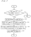
- Figs. 6 and 7 are flowcharts showing a procedure in calibrating the beam intensity in the recording apparatus 1.
- the parameters for the modulator elements are all set to 100 and the light source 11 is turned on. Following that, three modulator elements at center and both ends are brought to "On-state” so as to bring the modulator elements into correspondence with the photodetector elements(S12 and S13).
- the term "On-state” means the state where the modulator element is operated to render a signal light beam with the intensity according to the parameter.
- the photodetector 2 measures the "Off-state" intensity distribution with all the modulator elements are operated not to render a signal light beam(S14).
- a group of modulator elements which are spatially separate from one another is selected(S15). Then all the selected elements are brought to "On-state” and the beam intensities are measured by the photodetector 2(S16 and S17).
- Fig. 8 shows an example of an intensity profile with a group of selected elements in "On-state.” Each element is selected to be separate from the adjacent one by a distance of n(integer) elements. The dashed line describes the "Off-state" distribution.
- FIG. 9 shows an example of an intensity profile with a group of the elements next to the previous ones in "On-state.” Such measurements are repeated until all the modulator elements are selected.
- the intensity data are stored in the memory 401.
- Fig. 10 shows "On-state” and “Off-state” intensity profiles obtained after the repeated measurements.
- the poor uniformity of the profiles is mainly due to the non-uniform illumination on the light modulator 12.
- the correction parameter calculation means 34 finds out a correction parameter for each modulator element which makes the beam intensity the lowest value among the data(indicated as Imin in Fig. 10.) A typical relationship between the correction parameter and the beam intensity is shown in Fig. 11.
- the beam intensity calibration comes to an end(S21). Otherwise, the light power of the laser source 11 is adjusted to make the minimum intensity equal to a predetermined target intensity(S23) and the correction data are recalculated(S14 and S15).
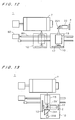
- the recording apparatus shown Fig. 12 includes a prism 221 and a relay optics 22. This constitution can be applied if the space facing the optics 13 is not big enough to dispose the photodetector 2.
- the relay optics 22 can have the function of (de)rnagnifying the image on the photodetector 2.
- any of the embodiments shown in Figs. 13, 14, and 15 has a optical head 10 which contains a photodetector 2.
- the optical head 10 shown in Fig. 13 further contains a turning mirror (prism) actuated by a motor 232 for switching between the recording path and the calibration path.
- Fig. 14 shows a optical head which has a relay optics 22 and a beam splitter 24 disposed between the light modulator 12 and the optics 13 for bringing means of the light beams to the relay optics 22.
- the optical head 10 shown in Fig. 15 contains a beam splitter 24 disposed between the optics 13 and the holding drum 7. Any of the opticalf heads in Figs. 13, 14,and 15 does not need moving to a predetermined calibration position.
- the light source 11 of the above preferred embodiments is not limited to a semiconductor laser bar, but may be a semiconductor laser having a single emitter or atwo-dimensionally arranged semiconductor laser array. Light sources other than the semiconductor laser may be also used.
- the light modulator 12 may have a constitution in which a plurality of two-dimensionally arranged light modulator elements 121. In this case, it is preferable that the photodetector elements 21 of the photodetector 2 should be also two-dimensionally arranged.
- the light modulator element 121 is not limited to theGrating Light ValveTM, but may be an electro-optic shutter array such a PLZT (lead lanthanum zirconium titanate) modulator and a TIR(total internal reflection) type of device.
- PLZT lead lanthanum zirconium titanate
- TIR total internal reflection
- the recording medium 9 is held by the holding drum 7 and the main scanning is performed by rotation of the holding drum 7 and the sub-scanning is performed by movement of the optical head 10 in the image recording apparatus 1, there may be a case where the recording medium 9 is held on a plane base and the main and sub-scanning are both performed by relative movement between the optical head 10 and the recording medium 9.
- the light beams from a plurality of light modulator elements 121 of the light modulator 12 which are subject to calibration are received by a plurality of photodetector elements 21 and if the photodetector elements outnumbers the light modulator elements 121 which are subject tocalibration, the calibration can be achieved with higher accuracy.
Landscapes
- Engineering & Computer Science (AREA)
- Physics & Mathematics (AREA)
- Optics & Photonics (AREA)
- General Engineering & Computer Science (AREA)
- General Physics & Mathematics (AREA)
- Theoretical Computer Science (AREA)
- Multimedia (AREA)
- Signal Processing (AREA)
- Exposure And Positioning Against Photoresist Photosensitive Materials (AREA)
- Printers Or Recording Devices Using Electromagnetic And Radiation Means (AREA)
- Laser Beam Printer (AREA)
- Optical Modulation, Optical Deflection, Nonlinear Optics, Optical Demodulation, Optical Logic Elements (AREA)
Abstract
Description
Claims (10)
- An image recording apparatus (1) for recording an image on a recording medium (9) by exposure, comprising:a light source (11);a light modulator (12) receiving light from said light source (11);a holding means (7) for holding said recording medium (9) which is exposed to signal light beams from said light modulator (12);a photodetector (2) having a plurality of photodetector elements (21);a recording optics for bringing said signal light beams to said recording medium(9);a detection optics (13) for bringing the signal beams from said light modulator (12) which are subject to beam intensity correction; andan correction electronics for providing correction data to said light modulator.
- The image recording apparatus according to claim 1, further comprising:a different optical path for beam intensity detection from that for recording an image.
- The image recording apparatus according to claim 2, wherein
a switching mechanism (82, 83) for switching between said optical path for beam intensity detection and said optical path for recording an image. - The image recording apparatus according to claim 1, wherein
said detection optics comprises a beam splitter for sampling means of each signal beam. - The image recording apparatus according to claim 1, wherein
said photodetector elements (21) outnumbers said light modulator elements (121). - The image recording apparatus according to claim 1, further comprising:a controller (33) for selecting a group of said light modulator elements (121) which are spatially separate from one another and sequentially reselecting one group after another until all of said light modulator elements (121) are selected.
- The image recording apparatus according to claim 1, wherein
the light power of said light source (11) is adjusted to make the corrected beam intensity equal to a predetermined target intensity. - A method of correcting intensities of signal beams from a plurality of light modulator elements (121) in an image recording apparatus (1), said method comprising:a selection step of selecting a group of modulator elements (121) which are spatially separate from one another;a measurement step of measuring the beam intensities of said group of modulator elements;a reselection step of selecting another group of modulator elements (121) until all of said modulator elements (121); anda calculation step of calculating correction data for all of said modulator elements (121).
- The method of correcting intensities of signal beams from a plurality of light modulator elements in an image recording apparatus according to claim 8, wherein
said correction data are determined so that all of said beam intensities can be equal to the minimum value among the measurement data acquired after the repeated intensity measurements. - The method of correcting quantities of output lights according to claim 8, further comprising:a light power adjustment step of adjusting the light power of said light source to make the beam intensity equal to a predetermined intensity.
Applications Claiming Priority (2)
| Application Number | Priority Date | Filing Date | Title |
|---|---|---|---|
| JP2001342768 | 2001-11-08 | ||
| JP2001342768A JP3583750B2 (en) | 2001-11-08 | 2001-11-08 | Image recording apparatus and output light amount correction method |
Publications (3)
| Publication Number | Publication Date |
|---|---|
| EP1311108A2 true EP1311108A2 (en) | 2003-05-14 |
| EP1311108A3 EP1311108A3 (en) | 2004-08-11 |
| EP1311108B1 EP1311108B1 (en) | 2009-12-09 |
Family
ID=19156567
Family Applications (1)
| Application Number | Title | Priority Date | Filing Date |
|---|---|---|---|
| EP02023813A Expired - Lifetime EP1311108B1 (en) | 2001-11-08 | 2002-10-23 | Method for correcting the beam intensity in an image recording apparatus using a multi-channel light modulator |
Country Status (4)
| Country | Link |
|---|---|
| US (1) | US6956596B2 (en) |
| EP (1) | EP1311108B1 (en) |
| JP (1) | JP3583750B2 (en) |
| DE (1) | DE60234671D1 (en) |
Cited By (2)
| Publication number | Priority date | Publication date | Assignee | Title |
|---|---|---|---|---|
| EP1898237A1 (en) * | 2006-09-07 | 2008-03-12 | Dainippon Screen Mfg., Co., Ltd. | Method and Apparatus for Correcting Output Light-Amounts of Spatial Light Modulator, Image Recording Apparatus, and Image Recording Method |
| EP1557786A3 (en) * | 2004-01-21 | 2008-12-31 | Xerox Corporation | Parallel beam to beam uniformity correction |
Families Citing this family (18)
| Publication number | Priority date | Publication date | Assignee | Title |
|---|---|---|---|---|
| US7616225B2 (en) * | 2002-10-10 | 2009-11-10 | Citizen Holdings Co., Ltd. | Exposure system and production method for exposure system |
| JP4312535B2 (en) * | 2003-08-06 | 2009-08-12 | シャープ株式会社 | Pattern exposure equipment |
| JP5126928B2 (en) * | 2005-04-20 | 2013-01-23 | 大日本スクリーン製造株式会社 | Image recording device |
| JP4553313B2 (en) * | 2005-10-31 | 2010-09-29 | 大日本スクリーン製造株式会社 | Image recording device |
| JP4912006B2 (en) * | 2006-03-24 | 2012-04-04 | 大日本スクリーン製造株式会社 | Image recording device |
| JP4885029B2 (en) * | 2007-03-28 | 2012-02-29 | 株式会社オーク製作所 | Exposure drawing device |
| TWI401538B (en) * | 2007-03-28 | 2013-07-11 | Orc Mfg Co Ltd | Exposure drawing device |
| US8243115B2 (en) * | 2009-10-30 | 2012-08-14 | Eastman Kodak Company | Method for adjusting a spatial light modulator |
| US20110102780A1 (en) | 2009-10-30 | 2011-05-05 | Karassiouk Valentine A | Calibration of a spatial light modulator |
| MX2019001777A (en) | 2016-08-19 | 2019-12-11 | Strauss Levi & Co | Laser finishing of apparel. |
| EP3704608A4 (en) | 2017-10-31 | 2021-08-18 | Levi Strauss & Co. | USE OF NEURAL NETWORKS IN THE CREATION OF CLOTHING DESIGNS |
| CN111565880B (en) | 2017-10-31 | 2022-09-23 | 利惠商业有限公司 | Laser finish machining design tool |
| US11313072B2 (en) | 2018-02-27 | 2022-04-26 | Levi Strauss & Co. | On-demand manufacturing of laser-finished apparel |
| US11051571B2 (en) * | 2018-02-27 | 2021-07-06 | Levi Strauss & Co. | Apparel design system including garment features with allocation insights |
| WO2020033605A1 (en) | 2018-08-07 | 2020-02-13 | Levi Strauss & Co. | Outdoor retail space structure |
| US11484080B2 (en) | 2018-11-30 | 2022-11-01 | Levi Strauss & Co. | Shadow neutral 3-D garment rendering |
| EP4004270A4 (en) | 2019-07-23 | 2023-07-05 | Levi Strauss & Co. | THREE-DIMENSIONAL PREVIEW OF LASER FINISHED GARMENTS |
| JP7410772B2 (en) * | 2020-03-24 | 2024-01-10 | 株式会社Screenホールディングス | Optical modulator inspection method and inspection device |
Family Cites Families (16)
| Publication number | Priority date | Publication date | Assignee | Title |
|---|---|---|---|---|
| JPS59129854A (en) * | 1983-01-18 | 1984-07-26 | Dainippon Screen Mfg Co Ltd | Light quantity correcting method in case of scanning and recording of picture |
| DE3534338A1 (en) * | 1985-09-26 | 1987-04-02 | Siemens Ag | ELECTROPHOTOGRAPHIC PRINTER WITH AN EXPOSURE ENERGY / CORRECTION DEVICE FOR THE OPTICAL CHARACTER GENERATOR |
| JP2996465B2 (en) * | 1988-01-21 | 1999-12-27 | 富士写真フイルム株式会社 | Light beam output adjusting device and adjusting method thereof |
| US5081597A (en) * | 1989-12-21 | 1992-01-14 | Xerox Corporation | Process for dynamically equalizing multichannel optical imaging systems |
| DE69310974T2 (en) * | 1992-03-25 | 1997-11-06 | Texas Instruments Inc | Built-in optical calibration system |
| US6011631A (en) * | 1996-01-31 | 2000-01-04 | Texas Instruments Incorporated | Uniform exposure of photosensitive medium by square intensity profiles for printing |
| JPH10100476A (en) * | 1996-09-16 | 1998-04-21 | Xerox Corp | Integral feedback assembly for vertical cavity laser diode |
| US6201559B1 (en) * | 1996-12-19 | 2001-03-13 | Minolta Co., Ltd. | Method for measuring the quantity of light emergent from an optical tip array and image forming apparatus provided with an optical tip array |
| US6188427B1 (en) * | 1997-04-23 | 2001-02-13 | Texas Instruments Incorporated | Illumination system having an intensity calibration system |
| JP3042523B1 (en) * | 1999-02-05 | 2000-05-15 | ミノルタ株式会社 | Solid-state scanning optical writing device, light amount correction method thereof, and light amount measuring device |
| DE19904750C2 (en) * | 1999-02-05 | 2002-03-07 | Agfa Gevaert Ag | Apparatus and method for exposing a digital image to photosensitive material |
| US6369936B1 (en) * | 1999-03-12 | 2002-04-09 | Kodak Polychrome Graphics Llc | Pixel intensity control in electro-optic modulators |
| US6479811B1 (en) * | 2000-03-06 | 2002-11-12 | Eastman Kodak Company | Method and system for calibrating a diffractive grating modulator |
| JP2001255664A (en) * | 2000-03-14 | 2001-09-21 | Fuji Photo Film Co Ltd | Image exposing method |
| JP2002351086A (en) * | 2001-03-22 | 2002-12-04 | Fuji Photo Film Co Ltd | Exposure device |
| US20030189634A1 (en) * | 2002-04-05 | 2003-10-09 | Agfa Corporation | Method and system for calibrating spatial light modulator of imaging engine |
-
2001
- 2001-11-08 JP JP2001342768A patent/JP3583750B2/en not_active Expired - Fee Related
-
2002
- 2002-10-23 DE DE60234671T patent/DE60234671D1/en not_active Expired - Lifetime
- 2002-10-23 EP EP02023813A patent/EP1311108B1/en not_active Expired - Lifetime
- 2002-10-30 US US10/283,377 patent/US6956596B2/en not_active Expired - Lifetime
Cited By (3)
| Publication number | Priority date | Publication date | Assignee | Title |
|---|---|---|---|---|
| EP1557786A3 (en) * | 2004-01-21 | 2008-12-31 | Xerox Corporation | Parallel beam to beam uniformity correction |
| EP1898237A1 (en) * | 2006-09-07 | 2008-03-12 | Dainippon Screen Mfg., Co., Ltd. | Method and Apparatus for Correcting Output Light-Amounts of Spatial Light Modulator, Image Recording Apparatus, and Image Recording Method |
| US7710628B2 (en) | 2006-09-07 | 2010-05-04 | Dainippon Screen Mfg. Co., Ltd. | Method and apparatus for correcting output light-amounts of spatial light modulator, image recording apparatus, and image recording method |
Also Published As
| Publication number | Publication date |
|---|---|
| EP1311108A3 (en) | 2004-08-11 |
| JP2003140355A (en) | 2003-05-14 |
| US6956596B2 (en) | 2005-10-18 |
| US20030085985A1 (en) | 2003-05-08 |
| JP3583750B2 (en) | 2004-11-04 |
| DE60234671D1 (en) | 2010-01-21 |
| EP1311108B1 (en) | 2009-12-09 |
Similar Documents
| Publication | Publication Date | Title |
|---|---|---|
| US6956596B2 (en) | Method for correcting the beam intensity in an image recording apparatus using a multi-channel light modulator | |
| US5132723A (en) | Method and apparatus for exposure control in light valves | |
| US5844591A (en) | Multibeam laser recording apparatus | |
| US7710628B2 (en) | Method and apparatus for correcting output light-amounts of spatial light modulator, image recording apparatus, and image recording method | |
| US8130374B2 (en) | Calibration of a spatial light modulator | |
| JP3254392B2 (en) | Evaluation chart and image recording device | |
| US5812892A (en) | Multi-beam image forming system | |
| EP0082644A2 (en) | Apparatus for measuring the area of image portion of image-bearing member | |
| JPH09197316A (en) | Exposing device | |
| JP3769895B2 (en) | Image forming apparatus | |
| US20080316458A1 (en) | Light Quantity Adjustment Method, Image Recording Method, and Device | |
| JP2004004716A (en) | Method and system for calibrating spatial light modulator of imaging engine | |
| JP3707073B2 (en) | Light intensity control method | |
| JP3772466B2 (en) | Image forming apparatus provided with solid scanning optical writing head and method for measuring light quantity of optical writing head | |
| US6650353B2 (en) | Method and system for focus control in imaging engine with spatial light modulator | |
| JP3374687B2 (en) | Solid-state scanning optical writing device and method for measuring light quantity thereof | |
| US6166376A (en) | Multi-beam scanning device | |
| KR100243157B1 (en) | Laser scanning unit module | |
| US5754286A (en) | Method of identifying defective picture element in image-wise exposure apparatus | |
| JP2006227345A (en) | Method and apparatus for detecting pixel light beam defect | |
| US7907249B2 (en) | Film exposer and method for exposing light-sensitive films | |
| JPH10142863A (en) | Image forming device | |
| EP1094950B1 (en) | Pixel intensity control in electro-optic modulators | |
| JP2025037490A (en) | Method and control device for spatial light modulator, and exposure apparatus | |
| JP3598699B2 (en) | Method for measuring gradation characteristics of solid-state scanning optical writing device |
Legal Events
| Date | Code | Title | Description |
|---|---|---|---|
| PUAI | Public reference made under article 153(3) epc to a published international application that has entered the european phase |
Free format text: ORIGINAL CODE: 0009012 |
|
| AK | Designated contracting states |
Designated state(s): AT BE BG CH CY CZ DE DK EE ES FI FR GB GR IE IT LI LU MC NL PT SE SK TR |
|
| AX | Request for extension of the european patent |
Extension state: AL LT LV MK RO SI |
|
| PUAL | Search report despatched |
Free format text: ORIGINAL CODE: 0009013 |
|
| AK | Designated contracting states |
Kind code of ref document: A3 Designated state(s): AT BE BG CH CY CZ DE DK EE ES FI FR GB GR IE IT LI LU MC NL PT SE SK TR |
|
| AX | Request for extension of the european patent |
Extension state: AL LT LV MK RO SI |
|
| 17P | Request for examination filed |
Effective date: 20041116 |
|
| AKX | Designation fees paid |
Designated state(s): DE FR GB |
|
| RBV | Designated contracting states (corrected) |
Designated state(s): DE FR GB |
|
| 17Q | First examination report despatched |
Effective date: 20070228 |
|
| GRAP | Despatch of communication of intention to grant a patent |
Free format text: ORIGINAL CODE: EPIDOSNIGR1 |
|
| GRAS | Grant fee paid |
Free format text: ORIGINAL CODE: EPIDOSNIGR3 |
|
| GRAA | (expected) grant |
Free format text: ORIGINAL CODE: 0009210 |
|
| RIN1 | Information on inventor provided before grant (corrected) |
Inventor name: HIRAWA, TAKAHIDE,C/O DAINIPPON SCREEN MFG. CO.,LTD Inventor name: KATAOKA,YOSHIKAZU,C/O DAINIPPON SCREEN MFG.CO.,LTD Inventor name: TAMAKI,EIICHI,C/ODAINIPPON SCREEN MFG.CO.,LTD |
|
| AK | Designated contracting states |
Kind code of ref document: B1 Designated state(s): DE FR GB |
|
| REG | Reference to a national code |
Ref country code: GB Ref legal event code: FG4D |
|
| REF | Corresponds to: |
Ref document number: 60234671 Country of ref document: DE Date of ref document: 20100121 Kind code of ref document: P |
|
| PLBE | No opposition filed within time limit |
Free format text: ORIGINAL CODE: 0009261 |
|
| STAA | Information on the status of an ep patent application or granted ep patent |
Free format text: STATUS: NO OPPOSITION FILED WITHIN TIME LIMIT |
|
| 26N | No opposition filed |
Effective date: 20100910 |
|
| REG | Reference to a national code |
Ref country code: DE Ref legal event code: R082 Ref document number: 60234671 Country of ref document: DE Representative=s name: KILIAN KILIAN & PARTNER, DE |
|
| REG | Reference to a national code |
Ref country code: DE Ref legal event code: R082 Ref document number: 60234671 Country of ref document: DE Representative=s name: KILIAN KILIAN & PARTNER, DE |
|
| REG | Reference to a national code |
Ref country code: DE Ref legal event code: R082 Ref document number: 60234671 Country of ref document: DE Representative=s name: KILIAN KILIAN & PARTNER, DE Effective date: 20150317 Ref country code: DE Ref legal event code: R081 Ref document number: 60234671 Country of ref document: DE Owner name: SCREEN HOLDINGS CO., LTD., JP Free format text: FORMER OWNER: DAINIPPON SCREEN MFG. CO., LTD., KYOTO, JP Effective date: 20150317 Ref country code: DE Ref legal event code: R082 Ref document number: 60234671 Country of ref document: DE Representative=s name: KILIAN KILIAN & PARTNER, DE Effective date: 20130130 Ref country code: DE Ref legal event code: R082 Ref document number: 60234671 Country of ref document: DE Representative=s name: KILIAN KILIAN & PARTNER MBB PATENTANWAELTE, DE Effective date: 20150317 Ref country code: DE Ref legal event code: R082 Ref document number: 60234671 Country of ref document: DE Representative=s name: KILIAN KILIAN & PARTNER MBB PATENTANWAELTE, DE Effective date: 20130130 |
|
| REG | Reference to a national code |
Ref country code: FR Ref legal event code: CD Owner name: SCREEN HOLDINGS CO., LTD. Effective date: 20150622 |
|
| REG | Reference to a national code |
Ref country code: FR Ref legal event code: PLFP Year of fee payment: 15 |
|
| REG | Reference to a national code |
Ref country code: FR Ref legal event code: PLFP Year of fee payment: 16 |
|
| REG | Reference to a national code |
Ref country code: FR Ref legal event code: PLFP Year of fee payment: 17 |
|
| PGFP | Annual fee paid to national office [announced via postgrant information from national office to epo] |
Ref country code: FR Payment date: 20190913 Year of fee payment: 18 |
|
| PGFP | Annual fee paid to national office [announced via postgrant information from national office to epo] |
Ref country code: DE Payment date: 20191008 Year of fee payment: 18 |
|
| PGFP | Annual fee paid to national office [announced via postgrant information from national office to epo] |
Ref country code: GB Payment date: 20191025 Year of fee payment: 18 |
|
| REG | Reference to a national code |
Ref country code: DE Ref legal event code: R119 Ref document number: 60234671 Country of ref document: DE |
|
| GBPC | Gb: european patent ceased through non-payment of renewal fee |
Effective date: 20201023 |
|
| PG25 | Lapsed in a contracting state [announced via postgrant information from national office to epo] |
Ref country code: FR Free format text: LAPSE BECAUSE OF NON-PAYMENT OF DUE FEES Effective date: 20201031 Ref country code: DE Free format text: LAPSE BECAUSE OF NON-PAYMENT OF DUE FEES Effective date: 20210501 |
|
| PG25 | Lapsed in a contracting state [announced via postgrant information from national office to epo] |
Ref country code: GB Free format text: LAPSE BECAUSE OF NON-PAYMENT OF DUE FEES Effective date: 20201023 |