EP1311037A1 - Connection support fitted with a retaining collar - Google Patents
Connection support fitted with a retaining collar Download PDFInfo
- Publication number
- EP1311037A1 EP1311037A1 EP02102516A EP02102516A EP1311037A1 EP 1311037 A1 EP1311037 A1 EP 1311037A1 EP 02102516 A EP02102516 A EP 02102516A EP 02102516 A EP02102516 A EP 02102516A EP 1311037 A1 EP1311037 A1 EP 1311037A1
- Authority
- EP
- European Patent Office
- Prior art keywords
- collar
- connection support
- cavity
- housing
- support according
- Prior art date
- Legal status (The legal status is an assumption and is not a legal conclusion. Google has not performed a legal analysis and makes no representation as to the accuracy of the status listed.)
- Granted
Links
- 239000012212 insulator Substances 0.000 claims abstract description 9
- 230000000717 retained effect Effects 0.000 description 2
- 230000014759 maintenance of location Effects 0.000 description 1
- 239000000463 material Substances 0.000 description 1
- 239000002184 metal Substances 0.000 description 1
- 239000007769 metal material Substances 0.000 description 1
Images
Classifications
-
- H—ELECTRICITY
- H01—ELECTRIC ELEMENTS
- H01R—ELECTRICALLY-CONDUCTIVE CONNECTIONS; STRUCTURAL ASSOCIATIONS OF A PLURALITY OF MUTUALLY-INSULATED ELECTRICAL CONNECTING ELEMENTS; COUPLING DEVICES; CURRENT COLLECTORS
- H01R13/00—Details of coupling devices of the kinds covered by groups H01R12/70 or H01R24/00 - H01R33/00
- H01R13/40—Securing contact members in or to a base or case; Insulating of contact members
- H01R13/42—Securing in a demountable manner
- H01R13/426—Securing by a separate resilient retaining piece supported by base or case, e.g. collar or metal contact-retention clip
-
- H—ELECTRICITY
- H01—ELECTRIC ELEMENTS
- H01R—ELECTRICALLY-CONDUCTIVE CONNECTIONS; STRUCTURAL ASSOCIATIONS OF A PLURALITY OF MUTUALLY-INSULATED ELECTRICAL CONNECTING ELEMENTS; COUPLING DEVICES; CURRENT COLLECTORS
- H01R24/00—Two-part coupling devices, or either of their cooperating parts, characterised by their overall structure
- H01R24/38—Two-part coupling devices, or either of their cooperating parts, characterised by their overall structure having concentrically or coaxially arranged contacts
- H01R24/40—Two-part coupling devices, or either of their cooperating parts, characterised by their overall structure having concentrically or coaxially arranged contacts specially adapted for high frequency
- H01R24/52—Two-part coupling devices, or either of their cooperating parts, characterised by their overall structure having concentrically or coaxially arranged contacts specially adapted for high frequency mounted in or to a panel or structure
-
- H—ELECTRICITY
- H01—ELECTRIC ELEMENTS
- H01R—ELECTRICALLY-CONDUCTIVE CONNECTIONS; STRUCTURAL ASSOCIATIONS OF A PLURALITY OF MUTUALLY-INSULATED ELECTRICAL CONNECTING ELEMENTS; COUPLING DEVICES; CURRENT COLLECTORS
- H01R13/00—Details of coupling devices of the kinds covered by groups H01R12/70 or H01R24/00 - H01R33/00
- H01R13/62—Means for facilitating engagement or disengagement of coupling parts or for holding them in engagement
- H01R13/627—Snap or like fastening
- H01R13/6277—Snap or like fastening comprising annular latching means, e.g. ring snapping in an annular groove
-
- H—ELECTRICITY
- H01—ELECTRIC ELEMENTS
- H01R—ELECTRICALLY-CONDUCTIVE CONNECTIONS; STRUCTURAL ASSOCIATIONS OF A PLURALITY OF MUTUALLY-INSULATED ELECTRICAL CONNECTING ELEMENTS; COUPLING DEVICES; CURRENT COLLECTORS
- H01R2103/00—Two poles
Definitions
- An object of the present invention is a connection support fitted with a retaining collar. It can be used more particularly in the field of coaxial connectors, especially connectors designed to receive coaxial sockets or female connectors.
- connection supports comprising a male connector or plug placed within a cavity of the support in such a way that the socket can be introduced into the cavity and in such a way that the plug is then inserted into a housing of the socket.
- these supports have a second contact made on an inner rim of the cavity of the support to co-operate with an outer rim of the socket.
- connection support known from the teaching of the document FR-A-2,809,538.
- This connection support comprises a housing and a coaxial connector.
- the coaxial connector is presented in a cavity of the housing.
- the coaxial connector comprises, firstly, a load contact and, secondly, a ground contact.
- the load contact takes the form of a plug extending into the cavity so as to stand perpendicularly to an entry face of the cavity.
- the ground contact takes the form of an elastic contact strip extending beyond an inner rim of the cavity.
- the cavity may receive a matching coaxial connector in such a way that the plug can be inserted into a housing of the matching connector, while the elastic contact strip presses against an external rim, which is also conductive, of this matching connector.
- the solution implemented to form this ground contact is to propose a circular ground contact.
- the circular ground contact fulfils both a retaining function and a conduction function.
- connection support which fulfils both a retaining function and a conduction function should be capable of ensuring high pressure of contact around the matching socket. This has the consequence of creating substantial friction on the conductive outer rim of the matching connector and hence of gradually damaging this rim and reducing its conductive capacities.
- the value of the invention precisely is that it dissociates the contact functions from the retaining functions. To this end, to dissociate the functions, the means used to perform each of these functions are dissociated.
- the connection support therefore comprises an additional retaining means. This retaining means is independent of the load and ground contacts.
- this retaining means takes the form of the collar.
- This collar is held in a same internal rim of the cavity as the rim beyond which the ground contact extends.
- these two elements namely the collar and the ground contact, are positioned at different depths inside the cavity so as to effectively disassociate these two functions.
- the retaining function is fulfilled in the deepest part so as the length of the zone of the external rim that rubs against the collar. The advantage lies in the fact that this terminal part has no conductive function.
- connection support comprising an insulator housing and a coaxial connector, the coaxial connector comprising at least one load contact and one ground contact, the load contact extending in a cavity of the housing and the ground contact going beyond an inner rim of this cavity, characterised in that the connection support comprises a retaining collar positioned in a groove formed in the inner rim of the cavity, the collar being designed to retain a matching connector that can be inserted into the cavity of the support.
- FIG. 1 shows a connection support 1 according to the invention.
- This connection support 1 comprises an insulator housing 2.
- a cavity 3 is formed so that an aperture 4 of this cavity 3 opens on to a front face 5 of the insulator housing 2.
- the insulator housing 2 also has a rear face 6 opposite the front face 5.
- the sectional view shown in figure 1 is such that the section is made perpendicularly, and is made between the front face 5 and the rear face 6.
- the connection support 1 also has a coaxial connector 7.
- This coaxial connector 7 comprises at least two contacts: a first contact called a load contact 8 and a second contact called a ground contact 9.
- the contacts 8 and 9 are both conductive and independent.
- the load contact 8 is, for example, a cylindrical plug extending into the cavity 3.
- this cylindrical plug 8 is inserted from the rear face 6 so as to present a front end 10, which is also cylindrical, inside the cavity 3.
- This front end 10 is furthermore presented, also perpendicularly, into the aperture 4 of the front face 5.
- a matching connector presented so as to face the aperture 4 and so as to be positioned perpendicularly to the front face 5, is designed so that it can be inserted into the cavity 3 and receive the front end 10 in one of its housings.
- the load contact 8 is retained at a back 11 on the rear face 6 side of the insulator housing 2.
- the ground contact 9 in this example is an elastic metal strip curved in such a way that it is presented at an inner rim 12 of the cavity 3.
- the cavity 3 has a groove 13 formed in this inner rim 12, in which the ground contact 9 is mounted.
- the contact 9 has a rear end 14 going beyond the rear face 6 side and being held thereon.
- It also has a flexible front portion 15 that is presented so that it goes beyond the inner rim 12.
- This front portion 15 has a flexibility defined in such a way that this strip can be shifted in parallel to the plane formed by the front face 5 and rear phase 6 and in these positions respectively so that it can go beyond the inner rim 12 or be pushed into the groove 13.
- the connection support 1 has a retaining collar 16.
- This retaining collar 16 is preferably mounted inside the cavity 3. To this end, since the matching connector is designed to be inserted in the cavity 3, this collar 16 is presented at the inner rim 12. Indeed, the role of the collar 16 is to tighten an outer rim of the matching connector, while remaining lightly held in a second groove 17 of the inner rim 12. In this inner position, the retaining collar is retained by the second groove 17 and, at the same time, compressed against the outer rim of the matching connector. It therefore fulfils its retaining function.
- the retaining collar 16 is made out of a metallic material.
- the retaining collar 16 is preferably elastic. This elasticity may be conferred, for example, by the material out of which this collar 16 is made. However, in one embodiment, in which this collar 16 has an open toroidal shape, greater elasticity may be obtained for the collar 16 by means of its aperture and because of its possible play or travel.
- the collar 16 has an overall annular or ring shape. However, this ring will have an aperture that enables the enlargement, as a function of the presence or absence of a matching connector, of an internal diameter of this ring.
- the collar 16 takes the form of a U-shaped pin. It has two legs, elastically arched toward each other in such a way that the minimum distance between the two legs with smaller than the outer diameter of the outer rim of the matching connector. Thus, when it is connected to the support, the two legs get elastically stressed on the outer rim, possibly by co-operating with a recessed feature on this rim.
- Figure 2 shows a first embodiment of the collar 16.
- the collar 16 has an open annular or ring shape and is provided with a holding lug 18.
- This holding lug 18 is used to retain the collar 16 in the housing 2.
- the housing preferably has a slot 19 on one face of the housing 2 inserted the collar 16 into the cavity 3 from the exterior of this housing 2.
- Figure 2 corresponds to a section view parallel to the front and rear faces 5 and 6. The slot 19 is presented on an inner face 20 side of the insulator housing 2.
- the collar 16 is also provided with a holding lug 18.
- This holding lug 18 is used to retain the collar 16 when it is subjected to elastic stresses, especially during connections and disconnections of the matching connector.
- the holding lug 18 is elbowed and comprises an elbow 21 so that a front portion 22 of the holding lug 18 is presented perpendicularly to the slot 19.
- the presence of this elbow 21 also guarantees the position of the collar 16 inside the cavity 3.
- the front lug 22 is preferably received in a matching housing in such a way that the position of the collar 16 in the cavity 3 is ensured.
- the collar here does not obstruct the central orifice.
- the housing 2 is covered with a casing 23 that obstructs the slot 19 when the connection support 1 is fully mounted.
- the slot 19 is covered by means of a casing 23 that ensures the closing of the casing and therefore ensures that the collar 16 is definitely held within the cavity 3.
- the collar 16 has no holding lug such as 18.
- the collar 16 corresponds to a simple open annulus.
- An outer diameter 24 of this ring is such that it is slightly greater than a width 25 of the slot 19.
- this collar 16 is stressed in such a way as to force its introduction from the slot 19.
- the retaining collar 16 elastically resumes its shape and then attains its stress-free external diameter 24 so as to prevent the exit of the collar 16 from the second groove 17 and hence from inside the housing 2.
- an inner rim 26 of the retaining collar 16 is rounded or chamfered so that cooperation with an outer rim of the matching connector takes place without catching.
- the second groove 17 and hence the collar 16 are positioned in the cavity at a depth 27 determined from the back 11.
- a depth 27 corresponds to a distance between the back 11 and the retaining collar 16. This distance 27 such that it corresponds approximately to a distance between a terminal end of the matching connector and a recess designed on the outer rim of this matching connector.
- the collar 16 may co-operate with the recess and thus ensure retention.
- this connection support is mounted inside a mobile telephone. It is used for example to receive a matching connector of this support so that, for example, it fulfils power supply functions.
Landscapes
- Coupling Device And Connection With Printed Circuit (AREA)
- Details Of Connecting Devices For Male And Female Coupling (AREA)
- Non-Disconnectible Joints And Screw-Threaded Joints (AREA)
- Dowels (AREA)
- Flanged Joints, Insulating Joints, And Other Joints (AREA)
- Multi-Conductor Connections (AREA)
Abstract
Description
- An object of the present invention is a connection support fitted with a retaining collar. It can be used more particularly in the field of coaxial connectors, especially connectors designed to receive coaxial sockets or female connectors. Indeed, there are known connection supports comprising a male connector or plug placed within a cavity of the support in such a way that the socket can be introduced into the cavity and in such a way that the plug is then inserted into a housing of the socket. Furthermore, these supports have a second contact made on an inner rim of the cavity of the support to co-operate with an outer rim of the socket. These connections are made by inserting one of the connector elements into the other. The value of the invention lies in the fact that it proposes a means to retain the matching slot when it is inserted into the connection support.
- In the prior art, there is a connection support known from the teaching of the document FR-A-2,809,538. This connection support comprises a housing and a coaxial connector. The coaxial connector is presented in a cavity of the housing. The coaxial connector comprises, firstly, a load contact and, secondly, a ground contact. The load contact takes the form of a plug extending into the cavity so as to stand perpendicularly to an entry face of the cavity. Furthermore, the ground contact takes the form of an elastic contact strip extending beyond an inner rim of the cavity. Thus, the cavity may receive a matching coaxial connector in such a way that the plug can be inserted into a housing of the matching connector, while the elastic contact strip presses against an external rim, which is also conductive, of this matching connector. In this document, the solution implemented to form this ground contact is to propose a circular ground contact. In this case, the circular ground contact fulfils both a retaining function and a conduction function.
- The problem raised by a connection support of this kind is that the ground contact which fulfils both a retaining function and a conduction function should be capable of ensuring high pressure of contact around the matching socket. This has the consequence of creating substantial friction on the conductive outer rim of the matching connector and hence of gradually damaging this rim and reducing its conductive capacities. The value of the invention precisely is that it dissociates the contact functions from the retaining functions. To this end, to dissociate the functions, the means used to perform each of these functions are dissociated. The connection support therefore comprises an additional retaining means. This retaining means is independent of the load and ground contacts.
- Preferably, this retaining means takes the form of the collar. This collar is held in a same internal rim of the cavity as the rim beyond which the ground contact extends. However, these two elements, namely the collar and the ground contact, are positioned at different depths inside the cavity so as to effectively disassociate these two functions. Furthermore, the retaining function is fulfilled in the deepest part so as the length of the zone of the external rim that rubs against the collar. The advantage lies in the fact that this terminal part has no conductive function.
- The invention relates to a connection support comprising an insulator housing and a coaxial connector, the coaxial connector comprising at least one load contact and one ground contact, the load contact extending in a cavity of the housing and the ground contact going beyond an inner rim of this cavity, characterised in that the connection support comprises a retaining collar positioned in a groove formed in the inner rim of the cavity, the collar being designed to retain a matching connector that can be inserted into the cavity of the support.
- The invention will be understood more clearly from the following description and from the appended figures. These figures are given purely by way of an indication and in no way restrict the scope of the invention. Of these figures:
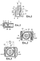
- Figure 1 is a longitudinal-section view of a connection support according to the invention;
- Figure 2 is a cross-section view of a first embodiment of the connection support according to the invention;
- Figure 3 is a cross-section view of a second embodiment of the connection support according to the invention
- Figure 4 is a cross-section view of a third embodiment of the connection support according to the invention.
-
- Figure 1 shows a
connection support 1 according to the invention. Thisconnection support 1 comprises aninsulator housing 2. In thisinsulator housing 2, acavity 3 is formed so that anaperture 4 of thiscavity 3 opens on to afront face 5 of theinsulator housing 2. Theinsulator housing 2 also has arear face 6 opposite thefront face 5. The sectional view shown in figure 1 is such that the section is made perpendicularly, and is made between thefront face 5 and therear face 6. - The
connection support 1 also has acoaxial connector 7. Thiscoaxial connector 7 comprises at least two contacts: a first contact called aload contact 8 and a second contact called aground contact 9. Thecontacts load contact 8 is, for example, a cylindrical plug extending into thecavity 3. Preferably, thiscylindrical plug 8 is inserted from therear face 6 so as to present afront end 10, which is also cylindrical, inside thecavity 3. Thisfront end 10 is furthermore presented, also perpendicularly, into theaperture 4 of thefront face 5. Thus, a matching connector, presented so as to face theaperture 4 and so as to be positioned perpendicularly to thefront face 5, is designed so that it can be inserted into thecavity 3 and receive thefront end 10 in one of its housings. Theload contact 8 is retained at aback 11 on therear face 6 side of theinsulator housing 2. - Furthermore, the
ground contact 9 in this example is an elastic metal strip curved in such a way that it is presented at aninner rim 12 of thecavity 3. Indeed, thecavity 3 has a groove 13 formed in thisinner rim 12, in which theground contact 9 is mounted. In this position, thecontact 9 has arear end 14 going beyond therear face 6 side and being held thereon. It also has aflexible front portion 15 that is presented so that it goes beyond theinner rim 12. Thisfront portion 15 has a flexibility defined in such a way that this strip can be shifted in parallel to the plane formed by thefront face 5 andrear phase 6 and in these positions respectively so that it can go beyond theinner rim 12 or be pushed into the groove 13. - The
connection support 1 has aretaining collar 16. This retainingcollar 16 is preferably mounted inside thecavity 3. To this end, since the matching connector is designed to be inserted in thecavity 3, thiscollar 16 is presented at theinner rim 12. Indeed, the role of thecollar 16 is to tighten an outer rim of the matching connector, while remaining lightly held in asecond groove 17 of theinner rim 12. In this inner position, the retaining collar is retained by thesecond groove 17 and, at the same time, compressed against the outer rim of the matching connector. It therefore fulfils its retaining function. - Preferably, the
retaining collar 16 is made out of a metallic material. Theretaining collar 16 is preferably elastic. This elasticity may be conferred, for example, by the material out of which thiscollar 16 is made. However, in one embodiment, in which thiscollar 16 has an open toroidal shape, greater elasticity may be obtained for thecollar 16 by means of its aperture and because of its possible play or travel. In this case, thecollar 16 has an overall annular or ring shape. However, this ring will have an aperture that enables the enlargement, as a function of the presence or absence of a matching connector, of an internal diameter of this ring. - In one variant, the
collar 16 takes the form of a U-shaped pin. It has two legs, elastically arched toward each other in such a way that the minimum distance between the two legs with smaller than the outer diameter of the outer rim of the matching connector. Thus, when it is connected to the support, the two legs get elastically stressed on the outer rim, possibly by co-operating with a recessed feature on this rim. - Figure 2 shows a first embodiment of the
collar 16. According to this first embodiment, thecollar 16 has an open annular or ring shape and is provided with a holdinglug 18. This holdinglug 18 is used to retain thecollar 16 in thehousing 2. In a preferred embodiment, the housing preferably has aslot 19 on one face of thehousing 2 inserted thecollar 16 into thecavity 3 from the exterior of thishousing 2. Figure 2 corresponds to a section view parallel to the front andrear faces slot 19 is presented on aninner face 20 side of theinsulator housing 2. - In the embodiment shown in figure 3, the
collar 16 is also provided with a holdinglug 18. This holdinglug 18 is used to retain thecollar 16 when it is subjected to elastic stresses, especially during connections and disconnections of the matching connector. And in this case, the holdinglug 18 is elbowed and comprises anelbow 21 so that afront portion 22 of the holdinglug 18 is presented perpendicularly to theslot 19. The presence of thiselbow 21 also guarantees the position of thecollar 16 inside thecavity 3. Indeed, thefront lug 22 is preferably received in a matching housing in such a way that the position of thecollar 16 in thecavity 3 is ensured. The collar here does not obstruct the central orifice. In this example, thehousing 2 is covered with acasing 23 that obstructs theslot 19 when theconnection support 1 is fully mounted. - In the alternative embodiments shown in figures 3 and 4, in both cases, the
slot 19 is covered by means of acasing 23 that ensures the closing of the casing and therefore ensures that thecollar 16 is definitely held within thecavity 3. - In a third embodiment shown in Figure 4, the
collar 16 has no holding lug such as 18. In this case, thecollar 16 corresponds to a simple open annulus. Anouter diameter 24 of this ring is such that it is slightly greater than awidth 25 of theslot 19. Thus, to insert thecollar 16 into thehousing 2, thiscollar 16 is stressed in such a way as to force its introduction from theslot 19. However, once it is inside thesecond groove 17, the retainingcollar 16 elastically resumes its shape and then attains its stress-freeexternal diameter 24 so as to prevent the exit of thecollar 16 from thesecond groove 17 and hence from inside thehousing 2. - In a preferred embodiment, an
inner rim 26 of the retainingcollar 16 is rounded or chamfered so that cooperation with an outer rim of the matching connector takes place without catching. - Preferably, the
second groove 17 and hence thecollar 16 are positioned in the cavity at adepth 27 determined from the back 11. For example, adepth 27 corresponds to a distance between the back 11 and the retainingcollar 16. Thisdistance 27 such that it corresponds approximately to a distance between a terminal end of the matching connector and a recess designed on the outer rim of this matching connector. In this case, thecollar 16 may co-operate with the recess and thus ensure retention. - In a preferred embodiment, this connection support is mounted inside a mobile telephone. It is used for example to receive a matching connector of this support so that, for example, it fulfils power supply functions.
Claims (9)
- Connection support (1) comprising an insulator housing (2) and a coaxial connector (7), the coaxial connector comprising at least one load contact (8) and one ground contact (9), the load contact extending in a cavity (3) of the housing and the ground contact going beyond an inner rim (12) of this cavity, characterised in that the connection support comprises a retaining collar (16) positioned in a groove (17) formed in the inner rim of the cavity, the collar being designed to retain a matching connector that can be inserted into the cavity of the support.
- Connection support according to claim 1 characterised in that the housing has a slot (19) on an outer rim (20) enabling the introduction of the collar into the groove from this slot.
- Connection support according to one of the claims 1 to 2 characterised in that the collar is elastic.
- Connection support according to one of the claims 1 to 3 characterised in that the collar has an open toroidal shape, for example corresponding to an open ring.
- Connection support according to one of the claims 1 to 3 characterised in that the collar forms an U-shaped pin.
- Connection support according to one of the claims 1 to 5 characterised in that the collar comprises a holding lug (18) to be held in the housing.
- Connection support according to one of the claims 1 to 6 characterised in that the collar is positioned in the cavity is such a way that it is designed to cooperate with a recess of the matching connector.
- Connection support according to one of the claims 1 to 7 characterised in that the load contact is plug-shaped and is inserted from a rear face (6) into the housing.
- Connection support according to one of the claims 1 to 8 characterised in that it fulfils a power supply function within a mobile telephone in which it is mounted.
Applications Claiming Priority (2)
| Application Number | Priority Date | Filing Date | Title |
|---|---|---|---|
| FR0114497 | 2001-11-08 | ||
| FR0114497A FR2831998A1 (en) | 2001-11-08 | 2001-11-08 | CONNECTION BASE PROVIDED WITH A RETENTION RING |
Publications (2)
| Publication Number | Publication Date |
|---|---|
| EP1311037A1 true EP1311037A1 (en) | 2003-05-14 |
| EP1311037B1 EP1311037B1 (en) | 2004-07-28 |
Family
ID=8869222
Family Applications (1)
| Application Number | Title | Priority Date | Filing Date |
|---|---|---|---|
| EP02102516A Expired - Lifetime EP1311037B1 (en) | 2001-11-08 | 2002-10-31 | Connection support fitted with a retaining collar |
Country Status (9)
| Country | Link |
|---|---|
| US (1) | US20030092290A1 (en) |
| EP (1) | EP1311037B1 (en) |
| JP (1) | JP2003197322A (en) |
| KR (1) | KR20030038478A (en) |
| CN (1) | CN1417897A (en) |
| AT (1) | ATE272257T1 (en) |
| DE (1) | DE60200824T2 (en) |
| FR (1) | FR2831998A1 (en) |
| TW (1) | TW571468B (en) |
Families Citing this family (1)
| Publication number | Priority date | Publication date | Assignee | Title |
|---|---|---|---|---|
| CN202183474U (en) * | 2011-07-01 | 2012-04-04 | 富士康(昆山)电脑接插件有限公司 | Electric connector |
Citations (3)
| Publication number | Priority date | Publication date | Assignee | Title |
|---|---|---|---|---|
| US5190474A (en) * | 1991-06-17 | 1993-03-02 | Radiall | Coaxial connector for connecting a coaxial cable to a printed electronic-circuit board |
| FR2682823A1 (en) * | 1991-10-18 | 1993-04-23 | Michelin & Cie | ELECTRICAL CONNECTOR LOCKING DEVICE. |
| JPH07288159A (en) * | 1994-04-18 | 1995-10-31 | Smk Corp | Switched jack and manufacturing method thereof |
-
2001
- 2001-11-08 FR FR0114497A patent/FR2831998A1/en not_active Withdrawn
-
2002
- 2002-10-25 TW TW091125081A patent/TW571468B/en active
- 2002-10-31 DE DE60200824T patent/DE60200824T2/en not_active Expired - Fee Related
- 2002-10-31 AT AT02102516T patent/ATE272257T1/en not_active IP Right Cessation
- 2002-10-31 EP EP02102516A patent/EP1311037B1/en not_active Expired - Lifetime
- 2002-11-06 US US10/288,859 patent/US20030092290A1/en not_active Abandoned
- 2002-11-07 KR KR1020020068645A patent/KR20030038478A/en not_active Withdrawn
- 2002-11-07 CN CN02150280A patent/CN1417897A/en active Pending
- 2002-11-08 JP JP2002324878A patent/JP2003197322A/en active Pending
Patent Citations (3)
| Publication number | Priority date | Publication date | Assignee | Title |
|---|---|---|---|---|
| US5190474A (en) * | 1991-06-17 | 1993-03-02 | Radiall | Coaxial connector for connecting a coaxial cable to a printed electronic-circuit board |
| FR2682823A1 (en) * | 1991-10-18 | 1993-04-23 | Michelin & Cie | ELECTRICAL CONNECTOR LOCKING DEVICE. |
| JPH07288159A (en) * | 1994-04-18 | 1995-10-31 | Smk Corp | Switched jack and manufacturing method thereof |
Non-Patent Citations (1)
| Title |
|---|
| PATENT ABSTRACTS OF JAPAN vol. 1996, no. 02 29 February 1996 (1996-02-29) * |
Also Published As
| Publication number | Publication date |
|---|---|
| DE60200824D1 (en) | 2004-09-02 |
| KR20030038478A (en) | 2003-05-16 |
| ATE272257T1 (en) | 2004-08-15 |
| FR2831998A1 (en) | 2003-05-09 |
| TW571468B (en) | 2004-01-11 |
| CN1417897A (en) | 2003-05-14 |
| US20030092290A1 (en) | 2003-05-15 |
| JP2003197322A (en) | 2003-07-11 |
| DE60200824T2 (en) | 2005-09-29 |
| EP1311037B1 (en) | 2004-07-28 |
Similar Documents
| Publication | Publication Date | Title |
|---|---|---|
| US5695368A (en) | Electrical terminal with protected locking lance and a connector therefor | |
| US5591039A (en) | Socket contact with arc arresting member | |
| US4070088A (en) | Contact construction | |
| KR101043512B1 (en) | Electrical contacts with wire trap | |
| US9083090B2 (en) | Plug-in wire connection terminal structure | |
| EP1009063A2 (en) | A connector | |
| US3544954A (en) | Pin and socket type electrical contact terminals | |
| JPH1167310A (en) | Large current charging terminal | |
| EP2755283B1 (en) | User Configurable Connector | |
| EP0221952A1 (en) | Wire seal. | |
| US20190393637A1 (en) | Terminal Metal Fitting | |
| US20030224658A1 (en) | Electrical connector | |
| US7753743B2 (en) | Electrical connector having retainer for securing terminals disposed therein | |
| US4269472A (en) | Electrical terminal | |
| US4707044A (en) | Butt contacts for an electrical connector | |
| KR200485888Y1 (en) | Multi-Consent easing Terminal Connection | |
| EP1311037B1 (en) | Connection support fitted with a retaining collar | |
| US5741159A (en) | Connector and connector kit | |
| JP3267240B2 (en) | Waterproof connector | |
| US20040224575A1 (en) | Low insertion force electrical socket contact | |
| JP2002222682A (en) | Shield connector | |
| KR100322055B1 (en) | Coaxial cable connector | |
| JPH04102167U (en) | contact | |
| JP2003031294A (en) | Waterproof connector | |
| JP2011146304A (en) | Electric connector |
Legal Events
| Date | Code | Title | Description |
|---|---|---|---|
| PUAI | Public reference made under article 153(3) epc to a published international application that has entered the european phase |
Free format text: ORIGINAL CODE: 0009012 |
|
| AK | Designated contracting states |
Designated state(s): AT BE BG CH CY CZ DE DK EE ES FI FR GB GR IE IT LI LU MC NL PT SE SK TR |
|
| AX | Request for extension of the european patent |
Extension state: AL LT LV MK RO SI |
|
| 17P | Request for examination filed |
Effective date: 20031021 |
|
| GRAP | Despatch of communication of intention to grant a patent |
Free format text: ORIGINAL CODE: EPIDOSNIGR1 |
|
| AKX | Designation fees paid |
Designated state(s): AT BE BG CH CY CZ DE DK EE ES FI FR GB GR IE IT LI LU MC NL PT SE SK TR |
|
| GRAS | Grant fee paid |
Free format text: ORIGINAL CODE: EPIDOSNIGR3 |
|
| GRAA | (expected) grant |
Free format text: ORIGINAL CODE: 0009210 |
|
| AK | Designated contracting states |
Kind code of ref document: B1 Designated state(s): AT BE BG CH CY CZ DE DK EE ES FI FR GB GR IE IT LI LU MC NL PT SE SK TR |
|
| PG25 | Lapsed in a contracting state [announced via postgrant information from national office to epo] |
Ref country code: IT Free format text: LAPSE BECAUSE OF FAILURE TO SUBMIT A TRANSLATION OF THE DESCRIPTION OR TO PAY THE FEE WITHIN THE PRESCRIBED TIME-LIMIT;WARNING: LAPSES OF ITALIAN PATENTS WITH EFFECTIVE DATE BEFORE 2007 MAY HAVE OCCURRED AT ANY TIME BEFORE 2007. THE CORRECT EFFECTIVE DATE MAY BE DIFFERENT FROM THE ONE RECORDED. Effective date: 20040728 Ref country code: BG Free format text: LAPSE BECAUSE OF FAILURE TO SUBMIT A TRANSLATION OF THE DESCRIPTION OR TO PAY THE FEE WITHIN THE PRESCRIBED TIME-LIMIT Effective date: 20040728 Ref country code: BE Free format text: LAPSE BECAUSE OF FAILURE TO SUBMIT A TRANSLATION OF THE DESCRIPTION OR TO PAY THE FEE WITHIN THE PRESCRIBED TIME-LIMIT Effective date: 20040728 Ref country code: CZ Free format text: LAPSE BECAUSE OF FAILURE TO SUBMIT A TRANSLATION OF THE DESCRIPTION OR TO PAY THE FEE WITHIN THE PRESCRIBED TIME-LIMIT Effective date: 20040728 Ref country code: CH Free format text: LAPSE BECAUSE OF FAILURE TO SUBMIT A TRANSLATION OF THE DESCRIPTION OR TO PAY THE FEE WITHIN THE PRESCRIBED TIME-LIMIT Effective date: 20040728 Ref country code: SK Free format text: LAPSE BECAUSE OF FAILURE TO SUBMIT A TRANSLATION OF THE DESCRIPTION OR TO PAY THE FEE WITHIN THE PRESCRIBED TIME-LIMIT Effective date: 20040728 Ref country code: LI Free format text: LAPSE BECAUSE OF FAILURE TO SUBMIT A TRANSLATION OF THE DESCRIPTION OR TO PAY THE FEE WITHIN THE PRESCRIBED TIME-LIMIT Effective date: 20040728 Ref country code: FI Free format text: LAPSE BECAUSE OF FAILURE TO SUBMIT A TRANSLATION OF THE DESCRIPTION OR TO PAY THE FEE WITHIN THE PRESCRIBED TIME-LIMIT Effective date: 20040728 Ref country code: TR Free format text: LAPSE BECAUSE OF FAILURE TO SUBMIT A TRANSLATION OF THE DESCRIPTION OR TO PAY THE FEE WITHIN THE PRESCRIBED TIME-LIMIT Effective date: 20040728 Ref country code: AT Free format text: LAPSE BECAUSE OF FAILURE TO SUBMIT A TRANSLATION OF THE DESCRIPTION OR TO PAY THE FEE WITHIN THE PRESCRIBED TIME-LIMIT Effective date: 20040728 Ref country code: CY Free format text: LAPSE BECAUSE OF FAILURE TO SUBMIT A TRANSLATION OF THE DESCRIPTION OR TO PAY THE FEE WITHIN THE PRESCRIBED TIME-LIMIT Effective date: 20040728 Ref country code: NL Free format text: LAPSE BECAUSE OF FAILURE TO SUBMIT A TRANSLATION OF THE DESCRIPTION OR TO PAY THE FEE WITHIN THE PRESCRIBED TIME-LIMIT Effective date: 20040728 Ref country code: EE Free format text: LAPSE BECAUSE OF FAILURE TO SUBMIT A TRANSLATION OF THE DESCRIPTION OR TO PAY THE FEE WITHIN THE PRESCRIBED TIME-LIMIT Effective date: 20040728 |
|
| REG | Reference to a national code |
Ref country code: GB Ref legal event code: FG4D |
|
| REG | Reference to a national code |
Ref country code: CH Ref legal event code: EP |
|
| REG | Reference to a national code |
Ref country code: IE Ref legal event code: FG4D |
|
| REF | Corresponds to: |
Ref document number: 60200824 Country of ref document: DE Date of ref document: 20040902 Kind code of ref document: P |
|
| PG25 | Lapsed in a contracting state [announced via postgrant information from national office to epo] |
Ref country code: DK Free format text: LAPSE BECAUSE OF FAILURE TO SUBMIT A TRANSLATION OF THE DESCRIPTION OR TO PAY THE FEE WITHIN THE PRESCRIBED TIME-LIMIT Effective date: 20041028 Ref country code: GR Free format text: LAPSE BECAUSE OF FAILURE TO SUBMIT A TRANSLATION OF THE DESCRIPTION OR TO PAY THE FEE WITHIN THE PRESCRIBED TIME-LIMIT Effective date: 20041028 Ref country code: SE Free format text: LAPSE BECAUSE OF FAILURE TO SUBMIT A TRANSLATION OF THE DESCRIPTION OR TO PAY THE FEE WITHIN THE PRESCRIBED TIME-LIMIT Effective date: 20041028 |
|
| PG25 | Lapsed in a contracting state [announced via postgrant information from national office to epo] |
Ref country code: LU Free format text: LAPSE BECAUSE OF NON-PAYMENT OF DUE FEES Effective date: 20041031 Ref country code: MC Free format text: LAPSE BECAUSE OF NON-PAYMENT OF DUE FEES Effective date: 20041031 |
|
| PG25 | Lapsed in a contracting state [announced via postgrant information from national office to epo] |
Ref country code: IE Free format text: LAPSE BECAUSE OF NON-PAYMENT OF DUE FEES Effective date: 20041101 |
|
| PG25 | Lapsed in a contracting state [announced via postgrant information from national office to epo] |
Ref country code: ES Free format text: LAPSE BECAUSE OF FAILURE TO SUBMIT A TRANSLATION OF THE DESCRIPTION OR TO PAY THE FEE WITHIN THE PRESCRIBED TIME-LIMIT Effective date: 20041108 |
|
| NLV1 | Nl: lapsed or annulled due to failure to fulfill the requirements of art. 29p and 29m of the patents act | ||
| ET | Fr: translation filed | ||
| REG | Reference to a national code |
Ref country code: CH Ref legal event code: PL |
|
| PLBE | No opposition filed within time limit |
Free format text: ORIGINAL CODE: 0009261 |
|
| STAA | Information on the status of an ep patent application or granted ep patent |
Free format text: STATUS: NO OPPOSITION FILED WITHIN TIME LIMIT |
|
| 26N | No opposition filed |
Effective date: 20050429 |
|
| REG | Reference to a national code |
Ref country code: IE Ref legal event code: MM4A |
|
| GBPC | Gb: european patent ceased through non-payment of renewal fee |
Effective date: 20061031 |
|
| PG25 | Lapsed in a contracting state [announced via postgrant information from national office to epo] |
Ref country code: GB Free format text: LAPSE BECAUSE OF NON-PAYMENT OF DUE FEES Effective date: 20061031 |
|
| PG25 | Lapsed in a contracting state [announced via postgrant information from national office to epo] |
Ref country code: PT Free format text: LAPSE BECAUSE OF NON-PAYMENT OF DUE FEES Effective date: 20041228 |
|
| PGFP | Annual fee paid to national office [announced via postgrant information from national office to epo] |
Ref country code: DE Payment date: 20071031 Year of fee payment: 6 |
|
| PGFP | Annual fee paid to national office [announced via postgrant information from national office to epo] |
Ref country code: FR Payment date: 20071004 Year of fee payment: 6 |
|
| REG | Reference to a national code |
Ref country code: FR Ref legal event code: ST Effective date: 20090630 |
|
| PG25 | Lapsed in a contracting state [announced via postgrant information from national office to epo] |
Ref country code: DE Free format text: LAPSE BECAUSE OF NON-PAYMENT OF DUE FEES Effective date: 20090501 |
|
| PG25 | Lapsed in a contracting state [announced via postgrant information from national office to epo] |
Ref country code: FR Free format text: LAPSE BECAUSE OF NON-PAYMENT OF DUE FEES Effective date: 20081031 |