The invention relates to an electrical connector for
detachably connecting a foil to electrically conductive
socket contacts of a socket housing
Electrical conductors in the form of conductive foils
are increasingly finding their way into many fields of
engineering, for example automotive engineering. In addition
to low production costs, the advantages of these foils are
their flexibility and low overall height and a high
electrical loading capacity. The latter is a consequence of
the high surface/volume ratio, in comparison to electrical
conductors with a round cross-section, resulting in improved
cooling of the conductors. The high electrical loading
capacity can be used for higher currents or for relatively
smaller conductor cross-sections having the same current
carrying capability.
Foils with a plurality of parallel conductor tracks
correspond to conventional multi-core conductors. The
interfaces with conventional conductors (for example cable
harnesses) or with power consuming devices (for example
electric motors or lighting fixtures) are a problem with
foils as the conventional connecting techniques (for example
soldering or welding) cannot be used. Therefore connectors
are interposed, of which the contacts create a spring loaded
connection to the conductor tracks of the foil and a
connection to conventional current conductors.
EP 0 926 778 A2 discloses a connector for detachably
connecting an electrically conductive foil to electrically
conductive socket contacts of a socket housing, wherein the
foil can be inserted into contact receiving apertures of
spring contacts of the socket contacts and can be jammed
therein. In the the socket contact there are resilient
points of contact in its aperture. A certain mating force,
with which the foil has to be inserted into the aperture, is
required to overcome them. However, this requires
considerably stiffness of the foil, so thin and flexible
foils cannot be used in this connector.
An object of the invention is therefore to create an
improved connector, a corresponding contact and an improved
housing for detachably connecting a foil to a socket
contact.
This and other objects are achieved with respect to the
connector wherein housings are connected when the socket
contact is open and connection proceeds virtually without
any mating force. The foil slot in the foil housing serves,
because of its long guide length, to guide the foil exactly
and with low friction. Consequently, and bnecause of the
open contact receiving aperture during connection of the
housings, very thin and flexible foils, which are
particularly inexpensive, can also be used.
Closure of the contact receiving aperture, which is
independent of the mating force-free connection of the
housings, and jamming of the foil brought about thereby
allows a high jamming force, ensuring good current
conduction between foil and socket contact and secure
locating of the foil in the connector.
It is advantageous that the foil housing comprises a
foil housing front wall, a foil housing base wall, a foil
housing top wall and two identical foil housing side walls,
the walls forming the foil housing which is open at the end
and into which the socket housing is insertable with play.
This results in a stable foil housing which is an important
precondition for mating force-free insertion of the socket
housing into the foil housing.
An advantage of the invention is that the first foil
slot is located in an outer foil receiving section and in a
plurality of inner foil receiving sections arranged
perpendicularly on the foil housing front wall and that the
inner foil receiving sections each have a foil stop limiting
the insertion depth of the foil. A long guide distance and a
defined end position of the foil in the foil housing is thus
achieved.
It is advantageous that a respective lever receiving
opening for a lever shaft of a lever are provided in the
foil housing side walls, and that the lever receiving
openings have a bearing slot opening them in the direction
of the foil housing top wall, the width of the slot being
smaller than the diameter of the lever receiving opening.
The width of the bearing slot is dimensioned such that,
because of the elasticity of the plastics material of the
foil housing, the lever shaft snaps with light pressure
through the bearing slots into the lever receiving openings.
The lever is thus captively connected to the foil housing.
As a result of the fact that the bearing slots have a
funnel-shaped lead in surface toward the foil housing top
wall, the lead in surface opening in a top wall opening of
corresponding width, the lever shaft is guided to the lever
receiving openings in a simple manner, and snaps therein.
For a stable socket housing and for exact guidance
thereof in the foil housing it is advantageous that the
socket housing has a socket housing front wall, a socket
housing back wall, two identical socket housing side walls,
a socket housing base wall and a socket housing top wall,
the socket housing fitting into the foil housing with play.
It is also conceivable to configure the housings in
such a way that the foil housing can be pushed into the
socket housing and the pivoted shaft is mounted in the
socket housing and the pivot lever can be locked to the foil
housing.
For the stability of the socket contact inserted into
the socket housing it is advantageous that partition plates
with identical spacing are provided in the socket housing
parallel to the socket housing side walls, between which
plates the socket contacts can be inserted through back wall
openings. When inserted through the back wall openings the
socket contacts are guided and protected against deformation
by the partition plates.
An advantageous development of the invention consists
in that the second foil slot for inserting the foil is
provided at the leading end of the socket housing in the
socket housing front wall and front wall openings for
inserting the inner foil receiving sections of the foil
housing and indentations in the partition plates for
enclosing and supporting the lever shaft are provided, the
foil and the inner foil receiving sections being inserted
and the lever shaft being enclosed when the housings are
connected. When the housings are connected complementary
components thus penetrate them, and this leads to multiple
support of the foil and the lever shaft and therefore to
their operational optimisation.
It is advantageous that the lever is pivotal between an
open and a closed position, the lever, which is resilient,
snapping into its closed position after overcoming at least
one locking nose arranged on the socket housing, so the
lever and the connected housings are locked.
Because of the locking according to the invention of
the lever the connector cannot be loosened by vibration.
This is important, above all, in the automotive sector.
Instead of the two locking noses on the side walls of the
socket housing just one can also be arranged in the centre
of the back wall of the socket.
As a result of the fact that a number of cams
corresponding to the number of socket contacts is non-rotatably
arranged on the lever shaft, owing to which cams
the foil is subjected to a predetermined normal contact
force via the spring contacts of the socket contacts when
the lever is locked, the foil is simultaneously jammed with
locking of the connector. Insertion and jamming of the foil
are thus clearly separated and optimised in each case.
It is also advantageous that the actuating force of the
lever is determined as a function of its pivotal angle owing
to the characteristic curve of the spring contacts and owing
to the gradient of the contour of the cams. As the
characteristic curve of the spring contacts of the socket
contact and the gradient of the contour of the cam can vary
within wide limits, the actuating force of the lever can be
varied accordingly and designed as desired.
A gradient of the contour of the cam decreasing with
increasing cam travel serves to limit the actuating force of
the lever.
An important aspect of the invention consists in that
the spring contacts comprise a first and a second spring
region and the first spring region comprises a first and a
second spring arm with free end faces arranged opposite one
another with spacing. The spring contacts are designed in
such a way that the desired progression of the
characteristic curve of the spring and therefore a
corresponding adjustment force of the lever is achieved by
varying the dimensions of their components.
The shape according to the invention of the spring
contacts provides the advantage of great variability in
their design. Therefore the characteristic curve of the
spring can be influenced by the length and width of the
first spring region and of the spring arms and by the
spacing of the opposing free end faces thereof.
Advantages also emerge from the fact that the socket
contacts comprise the spring contacts, a securing section
and a contact section, at least the securing section and the
spring contacts being formed in one piece. The securing
section brings about anchoring of the socket contact in the
socket housing. The spring contacts provide the spring
loaded connection of foil and socket contact. Their one-piece
design with the securing section simplifies
manufacture and reduces production costs. The contact
section serves to connect the socket contact to other
conductors, for example to conventional cables.
As a result of the fact that the contact receiving
aperture is limited by the second spring region and the
second spring arm, the foil comes into contact with
electrically conductive elements from both sides. The
electrically conductive parts of the foils must therefore be
arranged on the upper or lower side thereof. In the unlocked
state of the connector the contact receiving aperture is
completely open and does not offer any resistance when the
foil is inserted.
As the second spring region and the second spring arm
comprise opposing protrusions, between which the foils are
jammed when the connector is locked, the jamming force acts
at certain points on the foil and consequently produces a
high jamming pressure. This ensures good current conduction
to the foil and adequate jamming thereof.
It is advantageous that the contact sections are
designed as contact pins, contact clips or crimp contacts.
The connector according to the invention can thus be
connected to a wide variety of conductors. Examples include
inter alia printed circuit boards to which the contact pins
are soldered, or webs to which the contact clips are
connected, or cables which are bonded to the crimp contact.
The fact that the securing sections are preferably
designed in one piece with the contact pins and the contact
clips and the crimp contacts are connected to other securing
sections, preferably by laser welding, contributes to
reducing the cost of the connector.
As the securing sections comprise barbs on their upper
and lower edge, they can be anchored with interlocking fit
in the socket housing. Loosening of the socket contacts is
thus reliably prevented. This is important, above all, in
automotive use.
Further features of the invention can be found in the
following description and the drawings in which embodiments
of the invention are shown schematically, and in which:
Fig. 1 shows a cross-section through a connector 1
according to the invention in a perspective view. The
connector 1 is shown in the closed and locked state. It has
a foil housing 2 and a socket housing 3 which are inserted
in one another and locked by a lever 4.
The foil housing 2 has a foil housing front wall 5, a
foil housing base wall 6, a foil housing top wall 7 and two
foil housing side walls 8, which are not shown in Fig. 1.
The walls 5, 6, 7, 8 form a foil housing 2 open at the back,
into which the socket housing 3 can be inserted with play.
The foil housing 2 has a first foil slot 9 for
introduction of a foil 10. The socket housing 3 has a second
foil slot 11 aligning with the first foil slot 9 of the foil
housing 2. Both foil slots 9, 11 have broken edges at their
entry, facilitating introduction of the foil.
The first foil slot 9 is located in an outer foil
receiving section 12 and in inner foil receiving sections 13
arranged vertically on the front wall 5 of the foil housing
2. The inner foil receiving sections 13 are shown in Fig. 2.
These comprise a foil stop 14 limiting the insertion depth
of the foil 10.
There is preferably only a small amount of height play
between the first foil slot 9 and the foil 10, resulting in
good guidance thereof.
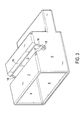
A respective lever receiving opening 15, of which one
is shown in Fig. 3, is arranged in the two side walls 8 of
the foil housing 2. These serve as bearings for a lever
shaft 16 of the lever 4. The lever receiving openings 15 are
opened in the direction of the foil housing top wall 7 by a
bearing slot 17, the width of the bearing slot 17 being
smaller than the diameter of the lever receiving opening 15.
The bearing slot 17 has a funnel-shaped lead in surface 18
ending in a top wall opening 19 of corresponding width.
In the assembly position a lever shaft 16 passes
through the top wall opening 19 and the funnel-shaped lead
in surface 18 above the bearing slot 17. With slight
pressure on the lever shaft 16 the latter snaps into the
lever receiving opening 15 while exploiting the elasticity
of the plastics material of the foil housing 2. Consequently
the lever 4 is captively connected to the foil housing 2.
The socket housing 3 has a socket housing front wall
20, a socket housing back wall 21, two identical socket
housing side walls 22, a socket housing base wall 23 and a
socket housing top wall 24. The walls 20, 21, 22, 23, 24
ensure the stability of the socket housing 3, so an optimum
precondition for exact guidance in the foil housing is
provided.
Partition plates 25 with identical spacing and forming
narrow gaps for socket contacts 26, 27, 28, are provided in
the socket housing 3 parallel to the socket housing side
walls 22. Each of these gaps has a back wall opening 29 in
the socket housing back wall 21, through which the
respective socket contact 26, 27, 28 is inserted. During
insertion and operation these socket contacts are guided and
protected against deformation by the partition plates 25.
The second foil slot 11 for inserting the foil 10 and
front wall openings (not shown) for inserting the inner foil
receiving sections 13 of the foil housing 2, are provided on
the leading end of the socket housing 3 in the socket
housing front wall 20. In addition, indentations 30, serving
to enclose and support the lever shaft 16 so the latter
cannot bend under load, are arranged in the leading ends of
the partition plates 25. The foil 10 and the inner foil
receiving sections 13 are inserted and the lever shaft 16
enclosed virtually without mating force when the housings 2,
3 are connected.
The lever 4 is pivotal about approximately 180° between
an open and a closed position. As it is resilient it can
snap into its closed position after overcoming two locking
noses 31. The locking noses 31 are provided at the upper,
foil-remote corners of the socket housing side walls 22. A
closing face 32 thereof is arranged somewhat set back with
respect to the socket housing back wall 21. The locking
force of the lever 4 presses thereon. The two housings 2, 3
are fixed owing to the lever 4 snapping into its closed
position. In this state the socket housing front wall 20 is
securely attached to the inner side of the foil housing
front wall 5.
Parallel, identically oriented cams 33 are non-rotatably
arranged on the lever shaft 16, as can be seen in
Fig. 4. The number and position of the cams 33 corresponds
to the number and position of socket contacts 26, 27, 28.
When the lever 4 is locked the foil 10 is subjected to a
predetermined normal contact force owing to the cams 33 via
socket pin contacts 26, as shown in Fig. 1 and 5.
The actuating force of the lever 4 is dependent on the
spring characteristic curve of the socket contacts 26, 27,
28 and on the gradient of the contour of the cams 33. As the
gradient decreases with increasing cam travel, the actuating
force of the lever 4 increases more slowly toward the closed
position.
The lever 4 is a retaining element designed as a
transverse rod in the form of a lever shaft 16 which is
connected to a closed clevis. The clevis has two
longitudinal arms 54 and a transverse arm 55 arranged
opposite the transverse rod. On an inner face the transverse
arm 55 has a retaining face 56 with which the socket housing
3 is retained on the foil housing 2. In the assembled state
of the lever 4 the two longitudinal arms 54 are guided
laterally along the foil housing 2. In a retaining position
the longitudinal arms 45 project in front of the foil
housing 2 and enclose the socket housing 3 inserted into the
foil housing 2. In a simple embodiment only one longitudinal
arm 54 is formed with a retaining face 56, instead of the
rotatably mounted pivoted clevis 4.
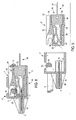
The plane sectional view in Fig. 5 shows the connector
1 in the open state. The socket housing 3 opposes the foil
housing 2 with spacing in the insertion position.
The tension lever 4 is snapped in the foil housing 2
and is in the open position with the cam 33. The foil 10 is
inserted in the first foil slot 9 and rests against the foil
stop 14.
There is a socket pin contact 26 in the socket housing
3. This consists of a spring contact 36, a securing section
35 and a contact section 34 designed as a contact pin 37.
The securing section 35 is inserted into the socket
housing 3 up to a contact stop 38 and owing to its barbs 39,
provided on an upper and a lower edge 52, 53 of the securing
section 35, is anchored with interlocking fit therein.
The spring contact 36 has an open contact receiving
aperture 40. The second foil slot 11 is located in front of
it. The indentation 30 for supporting the lever shaft 16 is
shown above the spring contact 36.
The connector 1 is closed by connecting the housings 2,
3. In the process the foil 10 passes through the second foil
slot 11 into the open contact receiving aperture 40 and
encloses the indentation 30, supporting the lever shaft 16.
This takes place virtually without mating force.
The connector 1 is locked by pivoting the lever 4 from
its open position in Fig. 5 into its closed position in Fig.
6. In the process it resiliently overcomes the locking nose
31 and comes to rest on the closing face 32. At the same
time the cam 13 reaches its maximum travel and loads the
spring contact 36. As a result the contact receiving
aperture 40 thereof is closed and the foil 10 inserted
therein is jammed. The jamming region of the foil is
stripped on both sides. Owing to the separate closing and
locking of the connector 1 the former is carried out without
mating force and the latter so as to be securely connected.
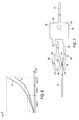
Fig. 7 shows a socket pin contact 26 with a securing
section 35, a spring contact 36 and a contact pin 37 which
together consist of one piece.
The spring contact 36 consists of a first and a second
spring region 41, 42. The first spring region 41 branches in
a first and a second spring arm 43, 44. The spring arms 43,
44 have free end faces 45 arranged opposite one another with
spacing.
The first spring arm 43 has a first protrusion 46 which
can be loaded by the cam 33. The second spring arm 44 has a
second protrusion 47 and the second spring region 42 a third
protrusion 48 which are arranged opposite and facing one
another and between which the stripped part of the foil 10
is jammed by the cam 33 via the first and second spring arm
43, 44 when the connector 1 is locked. A small jamming face
for jamming the foil 10 is provided by the second and third
protrusions 47, 48.
The small jamming face induces a high jamming pressure
ensuring good current conduction between the spring contact
36 and the foil 10 and adequate jamming thereof.
The contact receiving aperture 40 is limited by the
second spring region 42 and the second spring arm 44. As the
spring contact 36 as a whole is current-carrying it is
irrelevant whether the foil 10 is stripped in the jamming
region on one side only or on both sides.
Fig. 8 shows a graph in which the normal contact force
a between the protrusions 47, 48 and the actuating force b
of the lever 4 over the spring excursion s are shown.
The spring excursion s is divided into three zones. In
zone 1 only the first spring region 41 and the first spring
arm 43 operate and, more precisely, proceeding from 0 mm
spring excursion to contact of the foil 10 by the second
spring arm 44.
In zone 2 the first spring region 41 and the first and
second spring regions 43, 44 operate until the free end
faces 45 contact one another.
In zone 3 all three spring regions 41, 43, 44 operate,
the spring arms 43, 44 acting as a unit and thus increasing
the stiffness of the spring.
Owing to the change in length and width of the spring
regions 41, 43, 44 and by changing the spacing of the free
end faces 45, the normal contact force a and the actuating
force b can be varied and optimised.
Fig. 9 shows a socket pin contact 26 in a perspective
view, comprising the contact pin 37, the securing section
35, the contact spring 36 and the contact receiving aperture
40.
Fig. 10 shows a socket clip contact in a perspective
view. It differs from the socket pin contact 26 only in a
contact clip 49 in place of the contact pin 37. While the
contact pin 37 is suitable for soldering to a printed
circuit board, the contact clip 49 is placed on a web.
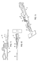
Fig. 11 shows a longitudinal section through a socket
crimp contact 28. This comprises the spring contact 36
which, with another securing section 35' forms a component.
The other securing section 35' can be inserted into a plug-in
housing 51 and can be connected thereto by laser welding.
The plug-in housing 51 is created by multiply folding a
sheet metal board. It is formed as one piece with the crimp
contact 50 which serves to connect a cable.
Fig. 12 shows a plan view of the socket crimp 28,
comprising the spring contact 36, the other securing section
35', the plug-in housing 51 and the crimp contact 50. The
position of the laser welding spots can be seen in Fig. 12.
Fig. 13 shows a perspective view of the socket crimp
contact 28 clearly showing the assembled construction
thereof.
The socket crimp contact 28 is anchored in the socket
housing 3 by means of a slip hook, not shown.
Fig. 14 is a perspective view of the other securing
section 35' with the spring contact 36, while Fig. 15 is a
perspective view of the plug-in housing 51 comprising the
crimp contact 50, which are each designed in one piece.
The connector according to the invention functions as
follows:
Firstly the lever 4 is snapped into the lever receiving
openings 15 of the foil housing 2 in the open position. The
foil 10 is then pushed into the first foil slot 9 up to the
foil stop 14. The socket contacts 26 or 27 or 28 are then
pushed into the socket housing 3 and then the socket housing
3 is pushed with minimal mating force into the foil housing
2. Finally, the lever 4 is pivoted from its open position
into its closed position. Consequently the connector 1 is
closed and locked, i.e. the housings 2, 3 are fixed and the
foil 10 is jammed. A shakeproof, easily detachable
connection to this foil is thus created.
The person skilled in the art can also mount the lever
4 in the socket housing 3, depending on the application. In
this embodiment the associated foil housing 2 then has a
corresponding locking nose 31 and closing face 32.