EP1310985A2 - Electrodeless lighting system - Google Patents
Electrodeless lighting system Download PDFInfo
- Publication number
- EP1310985A2 EP1310985A2 EP02013222A EP02013222A EP1310985A2 EP 1310985 A2 EP1310985 A2 EP 1310985A2 EP 02013222 A EP02013222 A EP 02013222A EP 02013222 A EP02013222 A EP 02013222A EP 1310985 A2 EP1310985 A2 EP 1310985A2
- Authority
- EP
- European Patent Office
- Prior art keywords
- magnetron
- waveguide
- lighting system
- high voltage
- microwave
- Prior art date
- Legal status (The legal status is an assumption and is not a legal conclusion. Google has not performed a legal analysis and makes no representation as to the accuracy of the status listed.)
- Withdrawn
Links
- 230000005540 biological transmission Effects 0.000 claims abstract description 5
- 238000001816 cooling Methods 0.000 claims description 31
- 239000012535 impurity Substances 0.000 abstract description 5
- 239000000428 dust Substances 0.000 abstract description 4
- 230000008595 infiltration Effects 0.000 abstract description 2
- 238000001764 infiltration Methods 0.000 abstract description 2
- 239000000463 material Substances 0.000 description 7
- 238000010438 heat treatment Methods 0.000 description 3
- 238000000034 method Methods 0.000 description 3
- 230000000903 blocking effect Effects 0.000 description 2
- 230000000694 effects Effects 0.000 description 2
- 230000003628 erosive effect Effects 0.000 description 2
- 238000009434 installation Methods 0.000 description 2
- 239000002184 metal Substances 0.000 description 2
- 230000001131 transforming effect Effects 0.000 description 2
- BUGBHKTXTAQXES-UHFFFAOYSA-N Selenium Chemical compound [Se] BUGBHKTXTAQXES-UHFFFAOYSA-N 0.000 description 1
- NINIDFKCEFEMDL-UHFFFAOYSA-N Sulfur Chemical compound [S] NINIDFKCEFEMDL-UHFFFAOYSA-N 0.000 description 1
- 239000000654 additive Substances 0.000 description 1
- 238000005422 blasting Methods 0.000 description 1
- 230000015556 catabolic process Effects 0.000 description 1
- 230000003247 decreasing effect Effects 0.000 description 1
- 230000007547 defect Effects 0.000 description 1
- 238000006731 degradation reaction Methods 0.000 description 1
- 150000002366 halogen compounds Chemical class 0.000 description 1
- 230000001939 inductive effect Effects 0.000 description 1
- 239000011261 inert gas Substances 0.000 description 1
- 238000012986 modification Methods 0.000 description 1
- 230000004048 modification Effects 0.000 description 1
- 239000010453 quartz Substances 0.000 description 1
- 229910052711 selenium Inorganic materials 0.000 description 1
- 239000011669 selenium Substances 0.000 description 1
- VYPSYNLAJGMNEJ-UHFFFAOYSA-N silicon dioxide Inorganic materials O=[Si]=O VYPSYNLAJGMNEJ-UHFFFAOYSA-N 0.000 description 1
- 238000001228 spectrum Methods 0.000 description 1
- 229910052717 sulfur Inorganic materials 0.000 description 1
- 239000011593 sulfur Substances 0.000 description 1
- 238000002834 transmittance Methods 0.000 description 1
- 238000009423 ventilation Methods 0.000 description 1
Images

Classifications
-
- H—ELECTRICITY
- H01—ELECTRIC ELEMENTS
- H01J—ELECTRIC DISCHARGE TUBES OR DISCHARGE LAMPS
- H01J65/00—Lamps without any electrode inside the vessel; Lamps with at least one main electrode outside the vessel
- H01J65/04—Lamps in which a gas filling is excited to luminesce by an external electromagnetic field or by external corpuscular radiation, e.g. for indicating plasma display panels
-
- H—ELECTRICITY
- H01—ELECTRIC ELEMENTS
- H01J—ELECTRIC DISCHARGE TUBES OR DISCHARGE LAMPS
- H01J61/00—Gas-discharge or vapour-discharge lamps
- H01J61/02—Details
- H01J61/52—Cooling arrangements; Heating arrangements; Means for circulating gas or vapour within the discharge space
-
- H—ELECTRICITY
- H01—ELECTRIC ELEMENTS
- H01J—ELECTRIC DISCHARGE TUBES OR DISCHARGE LAMPS
- H01J61/00—Gas-discharge or vapour-discharge lamps
- H01J61/02—Details
- H01J61/56—One or more circuit elements structurally associated with the lamp
-
- H—ELECTRICITY
- H01—ELECTRIC ELEMENTS
- H01J—ELECTRIC DISCHARGE TUBES OR DISCHARGE LAMPS
- H01J65/00—Lamps without any electrode inside the vessel; Lamps with at least one main electrode outside the vessel
- H01J65/04—Lamps in which a gas filling is excited to luminesce by an external electromagnetic field or by external corpuscular radiation, e.g. for indicating plasma display panels
- H01J65/042—Lamps in which a gas filling is excited to luminesce by an external electromagnetic field or by external corpuscular radiation, e.g. for indicating plasma display panels by an external electromagnetic field
- H01J65/044—Lamps in which a gas filling is excited to luminesce by an external electromagnetic field or by external corpuscular radiation, e.g. for indicating plasma display panels by an external electromagnetic field the field being produced by a separate microwave unit
Definitions
- the present invention relates to an electrodeless lighting system, and particularly, to an electrodeless lighting system which generates light using microwave generated from a magnetron.
- an electrodeless lighting system is a device for emitting visible rays or ultraviolet rays by applying microwave to an electrodeless lamp, and therefore, has longer life span than that of incandescent lamp or fluorescent lamp which is generally used, and has higher lighting effect.
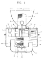
- Figure 1 is a longitudinal cross-sectional view showing a general electrodeless lighting system according to the conventional art.
- the conventional electrodeless lighting system comprises a high voltage generator 2 for transforming utility AC power to high voltage, and a magnetron 3 for generating microwave using the high voltage generated from the high voltage generator 2 in a case 1.
- a waveguide 4 for guiding the microwave generated from the magnetron 3 is fixed inside the case 1 between the magnetron 3 and the high voltage generator 2 so as to be exposed to outside through an opening portion 1a formed on the case 1.
- a bulb 6 in which a material emitted by the microwave energy is filled is located on an exit side of the waveguide 4. Also, a shaft through hole 4a is formed on intermediate part of the waveguide 4, and a rotation shaft 5 which is coupled to the bulb 6 passes through the shaft through hole 4a.
- a bulb motor 7 is installed on bottom side of the waveguide 4 so as to make the bulb rotate by the rotation shaft and prevent the bulb 6 from being heated locally.
- a resonator 8 of metal screen which is covered on outer side of the bulb 6 for blocking the leakage of the microwave transmitted from the magnetron 3 and for passing the light emitted from the bulb 6, is installed on an exit side of the waveguide 4 which is located on front side of the case 1.
- a reflector 9 is fixed on front side of the case 1 for reflecting the light generated from the bulb 6 and passed the resonator 8.
- a cooling device 13 is installed on rear side of the case 1 so as to cool down the magnetron 3 and the high voltage generator 2.
- the cooling device 13 comprises a fan housing 12 including discharge ports 12a and a suction port 12b, a fan motor 10, and a cooling fan 11.
- a plurality of exhaust holes 1b are formed on front side of the case 1 so that the air sucked through the suction port 12b cools down the high voltage generator 2 and the magnetron 3 and then is discharged to outside of the case 1.
- the high voltage generator 2 When the electric power is applied, the high voltage generator 2 generates high voltage, and the microwave is generated in the magnetron 3 by the generated high voltage.
- the microwave generated as above is transmitted into the resonator 8 through the waveguide 4, then, the material filled in the bulb 6 is discharged by the microwave and generates light by the plasma, and the light is illuminated to frontward as reflected by the reflector 9.
- the bulb motor 7 is rotated at a predetermined speed to rotate the bulb 6 so as to prevent the bulb 6 from being heated locally.
- the cooling fan 11 is rotated by the operation of the fan motor 10, and accordingly, the outside air sucked through the fan housing 12 cools down the high voltage generator 2 and the magnetron 3, after that, the air is discharged to outside of the case 1 through the exhaust holes 1b formed on front side of the case 1.
- the air is induced into the components such as the resonator 8 through the gap of the assembled components during the process of blasting the air when the cooling device is operated in order to cool down the high voltage generator 2 and the magnetron 3, impurities such as dust or bugs induced with the air may oxidize the components of the resonator 8 and etc. or decrease the function of the components by the high temperature around the bulb 6, whereby the life span of the lighting system may be decreased.
- an object of the present invention is to provide an electrodeless lighting system suitable for minimizing an emitting part by separating the order parts which are not virtually needed to emit from the emitting part.
- Another object of the present invention is to provide an electrodeless lighting system by which performance degradation and damage of a bulb which may be generated by the impurities such as dust can be prevented by preventing the air which is forcedly blasted in the cooling device from inducing into the components.
- an electrodeless lighting system comprising: a main case including a waveguide through which a microwave is transmitted, a resonator coupled to an exit of the waveguide, and a bulb located inside the resonator; a subsidiary case including a magnetron for generating the microwave, and a high voltage generator for providing the magnetron with high voltage; and a microwave transmission cable connected from the magnetron to the waveguide for transmitting the microwave.
- the main case is sealed except a part where the exit of the waveguide is exposed.
- the subsidiary case includes a cooling device in order to cool down the magnetron and the high voltage generator.
- the subsidiary case includes a suction hole and a discharge hole for circulating outside air
- the cooling device comprises a cooling fan for forcedly circulating the outside air inside the subsidiary case and a fan motor for driving the fan motor.
- an electrodeless lighting system comprising: a main case including a magnetron for generating the microwave, a waveguide for transmitting the microwave, and a resonator coupled to an exit of the waveguide, and a bulb located inside the resonator; a subsidiary case including a high voltage generator for providing the magnetron with the high voltage; and a coaxial cable connected from the high voltage generator to the magnetron for transmitting the high voltage.
- the main case includes a separating plate for dividing into an area where the magnetron is installed and an area where the waveguide is installed.
- a cooling device is installed on the area where the magnetron is installed so as to cool down the magnetron.
- a suction hole and a discharge hole are formed in the main case on the area where the magnetron is installed so as to circulate the outside air
- the cooling device includes a cooling fan for forcedly circulating outside air into the main case, and a fan motor driving the fan motor.
- the main case including the waveguide is sealed.
- the subsidiary case includes a ventilation hole so that the outside air can be induced.
- the emitting portion for emitting the light can be installed, and the size of the device can be reduced. Therefore, it can be easily installed, and has higher appearance when the installation is completed.
- the heating components and the emitting portion are separately installed in respective cases, or the air blasted from the cooling device is blocked so as not to be induced into the emitting portion, and thereby erosion on the resonator and the bulb caused by the dust induced with the outside air which is introduced into the emitting portions can be prevented.
- Figure 2 is a longitudinal cross-sectional view showing an electrodeless lighting system according to an embodiment of the present invention.
- the electrodeless lighting system comprises a subsidiary case 101 including a high voltage generator 102 for boosting utility AC power to high voltage, a magnetron 103 for generating microwave by the high voltage supplied from the high voltage generator 102, and a cooling fan 104 and fan motor 104a for cooling the magnetron 103 and the high voltage generator 102.
- the subsidiary case 101 further includes a suction hole 101 a and a discharge hole 101b so that outside air is sucked and discharged when the cooling fan 104 rotates.
- the electrodeless lighting system further comprises a main case 105, which is constructed apart from the subsidiary case 101, including a waveguide 106 for guiding the microwave generated from the magnetron 103, and a blub motor 109 for generating rotation force so as to cool down a bulb 108 which will be described later.
- a opening portion 105a is formed on an area where a part of the waveguide 106 is protruded through the main case 105, and the other parts of the main case 105 except the opening portion 105a are sealed.
- the waveguide 106 is fixed in the main case 105, and the bulb motor 109 is installed on bottom portion of the waveguide 106.
- An exit portion 106a of the waveguide 106 is exposed on front side of the main case 105 through the opening portion 105a, and a resonator 110 for blocking the leakage of the microwave and passing the light emitted from the bulb 108 is coupled to the exit portion 106a.
- a reflector 111 of conical shape which reflects the light generated from the bulb 108 and passed through the resonator 110, is fixed on front side of the main case 105 around the resonator 110.
- the bulb 108 is formed as a circle in which a material emitted by the microwave energy eradiated through the waveguide 106 is filled.
- the bulb 108 includes no electrode such as filament, has long or semipermanent life span.
- the material filled in the bulb 108 may be metal, halogen compounds, or sulfur and selenium which emits by forming plasma during the operation of the bulb 108, inert gas such as Ar, Xe, Kr for forming plasma inside the bulb 108 at an initial stage of emitting light, and additives for making the lighting to be easy by helping the initial discharge or for controlling spectrum of the generated light.
- the kinds, amount, or ratio of these materials are controlled according to the object of the illuminant.
- the bulb 108 is generally spherical or cylindrical form, and fabricated by the material of high light transmittance and little dielectric loss such as quartz.
- a shaft through hole 106a is formed on central portion of the waveguide 106, and a rotation shaft 107 which transmits rotation force from the bulb motor 109 to the bulb 108 passes through the shaft through hole 106a.
- a microwave transmission cable 112 is connected between the magnetron 103 installed inside the main case 105 and the waveguide 106 installed inside the subsidiary case 101 so as to transmit the microwave from the magnetron 103 to the waveguide 106.
- the microwave is outputted from the magnetron 103 by the high voltage generated from the high voltage generator 102.
- the outputted microwave is transmitted to the waveguide 106 installed inside the main case 105 through the microwave transmission cable 112, after that, the microwave is radiated to inside of the resonator 110 through the waveguide 106.
- the material filled in the bulb 108 is discharged by the microwave radiated inside the resonator 110 and plasma is generated, and thereby the light is emitted.
- the light passes through the resonator 110 and is irradiated to frontward, or a part of the light is reflected on the reflector 111 and irradiated to frontward.
- the bulb motor 109 is rotated at a predetermined speed to make the bulb 108 to rotate, and thereby heating and damage of local part on surface of the bulb 108 can be prevented.
- cooling fan 104 is operated in the subsidiary case 101 to cool down the high voltage generator 102 and the magnetron 103.
- the high voltage generator 102 and the magnetron 103 which emits high temperature are installed inside the subsidiary case 101 with the cooling fan 104, and the bulb 108 or the resonator 110 are installed inside the main case 105, whereby the size of the main case is reduced and the lighting system can be installed easily even if the space is small.
- the main case 105 is sealed, and therefore the impurities are not infiltrated into the resonator 110 and the waveguide 106, whereby the erosion or the defect of the components can be prevented.
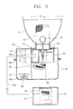
- FIG. 3 is a longitudinal cross-sectional view showing an electrodeless lighting system according to another embodiment of the present invention.
- same reference numerals as those of the above embodiment are used for components having same functions.
- the magnetron and the high voltage generator are installed in an additional subsidiary case, however, the high voltage generator is installed in the subsidiary case and the magnetron is installed in the main case according to the present embodiment.
- the high voltage generator 102 for transforming the utility AC power into the high voltage is installed in the subsidiary case 101.
- a suction hole 102a is formed on one side of the subsidiary case 101 so that the outside air is induced and the high voltage generator 102 can be cooled down.
- the main case 105 which is disposed apart from the subsidiary case 101 comprises the magnetron 103 for generating the microwave by connecting to the high voltage generator 102 with the coaxial cable 102a, the waveguide 105 for guiding the microwave generated from the magnetron 103, and the bulb motor 109 for generating rotation force so as to cool down the bulb 108.
- the resonator 110 installed on the exit 106a of the waveguide 106, the bulb 108, for generating light by the microwave, connected with the bulb motor 109 by the rotation shaft 107 inside the resonator 110, and the reflector 111 for reflecting the light generated in the bulb 108 to the frontward are installed on the front of the main case 105.
- a separating plate 302 for dividing an area where the magnetron 103 is located and an area where the waveguide 106 is located is installed inside the main case 105, and the separating plate 302 includes a hole 302a through which an outlet portion 103a of the magnetron 103 passes.
- a cooling fan 301 and a fan motor 301a are installed on the area where the magnetron 103 is located in the main case 105 for cooling down the magnetron 103.
- a suction hole 105b and a discharge hole 105c are formed on the main case 105 where the magnetron 103 is located so that the outside air is sucked and discharged according to the operation of the cooling fan 301.
- the main case 105 where the waveguide 106 is located is sealed with the separating plate 302.
- the high voltage generator is installed on an additional subsidiary case, and the area where the waveguide and the resonator are installed is sealed, and therefore the size of the main case can be reduced and the infiltration of the impurities into the area where the waveguide is installed can be prevented.
- the cooling fan and the fan motor are installed in order to cool down the high voltage generator or the magnetron in the above embodiments, however, methods such as a natural air convection by forming a hole on the respective cases, and a heat conduction method which radiates heat out of the case by installing heat pipe having higher heat conductivity may be used to cool down the high voltage generator and the magnetron.
Landscapes
- Physics & Mathematics (AREA)
- Engineering & Computer Science (AREA)
- Plasma & Fusion (AREA)
- Electromagnetism (AREA)
- Non-Portable Lighting Devices Or Systems Thereof (AREA)
- Discharge Lamps And Accessories Thereof (AREA)
- Circuit Arrangements For Discharge Lamps (AREA)
- Arrangement Of Elements, Cooling, Sealing, Or The Like Of Lighting Devices (AREA)
Abstract
Description
- The present invention relates to an electrodeless lighting system, and particularly, to an electrodeless lighting system which generates light using microwave generated from a magnetron.
- Generally, an electrodeless lighting system is a device for emitting visible rays or ultraviolet rays by applying microwave to an electrodeless lamp, and therefore, has longer life span than that of incandescent lamp or fluorescent lamp which is generally used, and has higher lighting effect.
- Figure 1 is a longitudinal cross-sectional view showing a general electrodeless lighting system according to the conventional art.
- As shown therein, the conventional electrodeless lighting system comprises a
high voltage generator 2 for transforming utility AC power to high voltage, and a magnetron 3 for generating microwave using the high voltage generated from thehigh voltage generator 2 in a case 1. - In addition, a waveguide 4 for guiding the microwave generated from the magnetron 3 is fixed inside the case 1 between the magnetron 3 and the
high voltage generator 2 so as to be exposed to outside through anopening portion 1a formed on the case 1. - A
bulb 6 in which a material emitted by the microwave energy is filled is located on an exit side of the waveguide 4. Also, a shaft throughhole 4a is formed on intermediate part of the waveguide 4, and arotation shaft 5 which is coupled to thebulb 6 passes through the shaft throughhole 4a. Abulb motor 7 is installed on bottom side of the waveguide 4 so as to make the bulb rotate by the rotation shaft and prevent thebulb 6 from being heated locally. - In addition, a
resonator 8 of metal screen, which is covered on outer side of thebulb 6 for blocking the leakage of the microwave transmitted from the magnetron 3 and for passing the light emitted from thebulb 6, is installed on an exit side of the waveguide 4 which is located on front side of the case 1. - A
reflector 9 is fixed on front side of the case 1 for reflecting the light generated from thebulb 6 and passed theresonator 8. - Also, a
cooling device 13 is installed on rear side of the case 1 so as to cool down the magnetron 3 and thehigh voltage generator 2. Thecooling device 13 comprises afan housing 12 includingdischarge ports 12a and asuction port 12b, afan motor 10, and acooling fan 11. - A plurality of
exhaust holes 1b are formed on front side of the case 1 so that the air sucked through thesuction port 12b cools down thehigh voltage generator 2 and the magnetron 3 and then is discharged to outside of the case 1. - The operation of the conventional electrodeless lighting system described above will be described as follows.
- When the electric power is applied, the
high voltage generator 2 generates high voltage, and the microwave is generated in the magnetron 3 by the generated high voltage. - The microwave generated as above is transmitted into the
resonator 8 through the waveguide 4, then, the material filled in thebulb 6 is discharged by the microwave and generates light by the plasma, and the light is illuminated to frontward as reflected by thereflector 9. - In addition, when the light is generated from the
bulb 6, thebulb motor 7 is rotated at a predetermined speed to rotate thebulb 6 so as to prevent thebulb 6 from being heated locally. - At the same time, the
cooling fan 11 is rotated by the operation of thefan motor 10, and accordingly, the outside air sucked through the fan housing 12 cools down thehigh voltage generator 2 and the magnetron 3, after that, the air is discharged to outside of the case 1 through theexhaust holes 1b formed on front side of the case 1. - However, according to the conventional electrodeless lighting system, only the
bulb 6, theresonator 8 and etc. are really needed to emitting light, however, almost all the components are installed inside the case 1, and therefore the volume of the lighting system is increased and takes a large space when it is installed. And it may be very difficult to apply the lighting system in case that the installation space is small. - Also, according to the conventional electrodeless lighting system, if the air is induced into the components such as the
resonator 8 through the gap of the assembled components during the process of blasting the air when the cooling device is operated in order to cool down thehigh voltage generator 2 and the magnetron 3, impurities such as dust or bugs induced with the air may oxidize the components of theresonator 8 and etc. or decrease the function of the components by the high temperature around thebulb 6, whereby the life span of the lighting system may be decreased. - Therefore, an object of the present invention is to provide an electrodeless lighting system suitable for minimizing an emitting part by separating the order parts which are not virtually needed to emit from the emitting part.
- Another object of the present invention is to provide an electrodeless lighting system by which performance degradation and damage of a bulb which may be generated by the impurities such as dust can be prevented by preventing the air which is forcedly blasted in the cooling device from inducing into the components.
- To achieve these and other advantages and in accordance with the purpose of the present invention, as embodied and broadly described herein, there is provided an electrodeless lighting system comprising: a main case including a waveguide through which a microwave is transmitted, a resonator coupled to an exit of the waveguide, and a bulb located inside the resonator; a subsidiary case including a magnetron for generating the microwave, and a high voltage generator for providing the magnetron with high voltage; and a microwave transmission cable connected from the magnetron to the waveguide for transmitting the microwave.
- The main case is sealed except a part where the exit of the waveguide is exposed.
- The subsidiary case includes a cooling device in order to cool down the magnetron and the high voltage generator.
- In addition, the subsidiary case includes a suction hole and a discharge hole for circulating outside air, and the cooling device comprises a cooling fan for forcedly circulating the outside air inside the subsidiary case and a fan motor for driving the fan motor.
- Also, to achieve the objects of the present invention, there is provided an electrodeless lighting system comprising: a main case including a magnetron for generating the microwave, a waveguide for transmitting the microwave, and a resonator coupled to an exit of the waveguide, and a bulb located inside the resonator; a subsidiary case including a high voltage generator for providing the magnetron with the high voltage; and a coaxial cable connected from the high voltage generator to the magnetron for transmitting the high voltage.
- The main case includes a separating plate for dividing into an area where the magnetron is installed and an area where the waveguide is installed.
- A cooling device is installed on the area where the magnetron is installed so as to cool down the magnetron.
- A suction hole and a discharge hole are formed in the main case on the area where the magnetron is installed so as to circulate the outside air, and the cooling device includes a cooling fan for forcedly circulating outside air into the main case, and a fan motor driving the fan motor.
- The main case including the waveguide is sealed.
- The subsidiary case includes a ventilation hole so that the outside air can be induced.
- The electrodeless lighting system constructed above, the components which are heating such as the magnetron and the high voltage generator are installed inside the subsidiary case with the cooling device, and the components which are necessarily needed to emit the light such as the bulb, the resonator, and the waveguide are installed in the main case which is installed separately with the subsidiary case. Thereby, only the emitting portion for emitting the light can be installed, and the size of the device can be reduced. Therefore, it can be easily installed, and has higher appearance when the installation is completed.
- Also, the heating components and the emitting portion are separately installed in respective cases, or the air blasted from the cooling device is blocked so as not to be induced into the emitting portion, and thereby erosion on the resonator and the bulb caused by the dust induced with the outside air which is introduced into the emitting portions can be prevented.
- The foregoing and other objects, features, aspects and advantages of the present invention will become more apparent from the following detailed description of the present invention when taken in conjunction with the accompanying drawings.
- The accompanying drawings, which are included to provide a further understanding of the invention and are incorporated in and constitute a part of this specification, illustrate embodiments of the invention and together with the description serve to explain the principles of the invention.
- In the drawings:
- Figure 1 is a longitudinal cross-sectional view showing a conventional electrodeless lighting system;
- Figure 2 is a longitudinal cross-sectional view showing an electrodeless lighting system according to an embodiment of the present invention; and
- Figure 3 is a longitudinal cross-sectional view showing an electrodeless lighting system according to another embodiment of the present invention.
-
- Reference will now be made in detail to the preferred embodiments of the present invention, examples of which are illustrated in the accompanying drawings.
- Figure 2 is a longitudinal cross-sectional view showing an electrodeless lighting system according to an embodiment of the present invention.
- As shown therein, the electrodeless lighting system comprises a
subsidiary case 101 including ahigh voltage generator 102 for boosting utility AC power to high voltage, amagnetron 103 for generating microwave by the high voltage supplied from thehigh voltage generator 102, and acooling fan 104 andfan motor 104a for cooling themagnetron 103 and thehigh voltage generator 102. - The
subsidiary case 101 further includes asuction hole 101 a and adischarge hole 101b so that outside air is sucked and discharged when thecooling fan 104 rotates. - The electrodeless lighting system further comprises a
main case 105, which is constructed apart from thesubsidiary case 101, including awaveguide 106 for guiding the microwave generated from themagnetron 103, and ablub motor 109 for generating rotation force so as to cool down abulb 108 which will be described later. - Herein, a
opening portion 105a is formed on an area where a part of thewaveguide 106 is protruded through themain case 105, and the other parts of themain case 105 except theopening portion 105a are sealed. In addition, thewaveguide 106 is fixed in themain case 105, and thebulb motor 109 is installed on bottom portion of thewaveguide 106. - An
exit portion 106a of thewaveguide 106 is exposed on front side of themain case 105 through theopening portion 105a, and aresonator 110 for blocking the leakage of the microwave and passing the light emitted from thebulb 108 is coupled to theexit portion 106a. - Also, a
reflector 111 of conical shape, which reflects the light generated from thebulb 108 and passed through theresonator 110, is fixed on front side of themain case 105 around theresonator 110. - The
bulb 108 is formed as a circle in which a material emitted by the microwave energy eradiated through thewaveguide 106 is filled. - The
bulb 108 includes no electrode such as filament, has long or semipermanent life span. In addition, the material filled in thebulb 108 may be metal, halogen compounds, or sulfur and selenium which emits by forming plasma during the operation of thebulb 108, inert gas such as Ar, Xe, Kr for forming plasma inside thebulb 108 at an initial stage of emitting light, and additives for making the lighting to be easy by helping the initial discharge or for controlling spectrum of the generated light. In addition, the kinds, amount, or ratio of these materials are controlled according to the object of the illuminant. - The
bulb 108 is generally spherical or cylindrical form, and fabricated by the material of high light transmittance and little dielectric loss such as quartz. - On the other hand, a shaft through
hole 106a is formed on central portion of thewaveguide 106, and arotation shaft 107 which transmits rotation force from thebulb motor 109 to thebulb 108 passes through the shaft throughhole 106a. - Especially, a
microwave transmission cable 112 is connected between themagnetron 103 installed inside themain case 105 and thewaveguide 106 installed inside thesubsidiary case 101 so as to transmit the microwave from themagnetron 103 to thewaveguide 106. - Operation and effect of the electrodeless lighting system according to the embodiment of the present invention constructed as above will be described as follows.
- When electric power is applied to the
high voltage generator 102 installed inside thesubsidiary case 101, the microwave is outputted from themagnetron 103 by the high voltage generated from thehigh voltage generator 102. - The outputted microwave is transmitted to the
waveguide 106 installed inside themain case 105 through themicrowave transmission cable 112, after that, the microwave is radiated to inside of theresonator 110 through thewaveguide 106. - At that time, the material filled in the
bulb 108 is discharged by the microwave radiated inside theresonator 110 and plasma is generated, and thereby the light is emitted. In addition, the light passes through theresonator 110 and is irradiated to frontward, or a part of the light is reflected on thereflector 111 and irradiated to frontward. - On the other hand, when the light is emitted from the
bulb 108, thebulb motor 109 is rotated at a predetermined speed to make thebulb 108 to rotate, and thereby heating and damage of local part on surface of thebulb 108 can be prevented. - Also, the cooling
fan 104 is operated in thesubsidiary case 101 to cool down thehigh voltage generator 102 and themagnetron 103. - Therefore, according to the electrodeless lighting system of the above embodiment, the
high voltage generator 102 and themagnetron 103 which emits high temperature are installed inside thesubsidiary case 101 with the coolingfan 104, and thebulb 108 or theresonator 110 are installed inside themain case 105, whereby the size of the main case is reduced and the lighting system can be installed easily even if the space is small. - Also, the
main case 105 is sealed, and therefore the impurities are not infiltrated into theresonator 110 and thewaveguide 106, whereby the erosion or the defect of the components can be prevented. - Figure 3 is a longitudinal cross-sectional view showing an electrodeless lighting system according to another embodiment of the present invention. For convenience' sake, same reference numerals as those of the above embodiment are used for components having same functions.
- In the above embodiment, the magnetron and the high voltage generator are installed in an additional subsidiary case, however, the high voltage generator is installed in the subsidiary case and the magnetron is installed in the main case according to the present embodiment.
- That is, the
high voltage generator 102 for transforming the utility AC power into the high voltage is installed in thesubsidiary case 101. - Herein, a
suction hole 102a is formed on one side of thesubsidiary case 101 so that the outside air is induced and thehigh voltage generator 102 can be cooled down. - The
main case 105 which is disposed apart from thesubsidiary case 101 comprises themagnetron 103 for generating the microwave by connecting to thehigh voltage generator 102 with thecoaxial cable 102a, thewaveguide 105 for guiding the microwave generated from themagnetron 103, and thebulb motor 109 for generating rotation force so as to cool down thebulb 108. - In addition, the
resonator 110 installed on theexit 106a of thewaveguide 106, thebulb 108, for generating light by the microwave, connected with thebulb motor 109 by therotation shaft 107 inside theresonator 110, and thereflector 111 for reflecting the light generated in thebulb 108 to the frontward are installed on the front of themain case 105. - Especially, a separating
plate 302 for dividing an area where themagnetron 103 is located and an area where thewaveguide 106 is located is installed inside themain case 105, and the separatingplate 302 includes ahole 302a through which anoutlet portion 103a of themagnetron 103 passes. In addition, a coolingfan 301 and afan motor 301a are installed on the area where themagnetron 103 is located in themain case 105 for cooling down themagnetron 103. - And a
suction hole 105b and adischarge hole 105c are formed on themain case 105 where themagnetron 103 is located so that the outside air is sucked and discharged according to the operation of the coolingfan 301. - In addition, the
main case 105 where thewaveguide 106 is located is sealed with the separatingplate 302. - According to the electrodeless lighting system according to the another embodiment of the present invention, the high voltage generator is installed on an additional subsidiary case, and the area where the waveguide and the resonator are installed is sealed, and therefore the size of the main case can be reduced and the infiltration of the impurities into the area where the waveguide is installed can be prevented.
- On the other hand, the cooling fan and the fan motor are installed in order to cool down the high voltage generator or the magnetron in the above embodiments, however, methods such as a natural air convection by forming a hole on the respective cases, and a heat conduction method which radiates heat out of the case by installing heat pipe having higher heat conductivity may be used to cool down the high voltage generator and the magnetron.
- As the present invention may be embodied in several forms without departing from the spirit or essential characteristics thereof, it should also be understood that the above-described embodiments are not limited by any of the details of the foregoing description, unless otherwise specified, but rather should be construed broadly within its spirit and scope as defined in the appended claims, and therefore all changes and modifications that fall within the metes and bounds of the claims, or equivalence of such metes and bounds are therefore intended to be embraced by the appended claims.
Claims (10)
- An electrodeless lighting system comprising:a main case including a waveguide through which microwave is transmitted, a resonator coupled to an exit of the waveguide, and a bulb located in the resonator;a subsidiary case including a magnetron generating the microwave, and a high voltage generator for providing the magnetron with high voltage; anda microwave transmission cable connected from the magnetron to the waveguide for transmitting the microwave.
- The lighting system of claim 1, wherein the main case is sealed except a part where the exit of the waveguide is exposed.
- The lighting system of claim 1, wherein a cooling device is included in the subsidiary case in order to cool down the magnetron and the high voltage generator.
- The lighting system of claim 3, wherein the subsidiary case includes a suction hole and a discharge hole so that outside air can be circulated; and
the cooling device includes a cooling fan for forcedly circulating the outside air into the subsidiary case, and a fan motor driving the cooling fan. - An electrodeless lighting system comprising:a main case including a magnetron generating microwave, a waveguide through which the microwave is transmitted, a resonator coupled to an exit of the waveguide, and a bulb located in the resonator;a subsidiary case including a high voltage generator for providing the magnetron with the high voltage; anda coaxial cable connected from the high voltage generator to the magnetron for transmitting the high voltage to the magnetron.
- The lighting system of claim 5, wherein the main case includes a separating plate so as to divide an area where the magnetron is positioned and an area where the waveguide is positioned in the main case.
- The lighting system of claim 6, wherein a cooling device is installed on the area where the magnetron is positioned so as to cool down the magnetron.
- The lighting system of claim 7, wherein the main case in which the magnetron is installed has a suction hole and a discharge hole so that outside air can be circulated; and
the cooling device includes a cooling fan for forcedly ciculating the outside air inside the main case, and a fan motor driving the cooling fan. - The lighting system of claim 6, wherein the main case in which the waveguide is installed is sealed.
- The lighting system of claim 5, wherein the subsidiary case includes a ventilating hole so that the outside air can be induced therein.
Applications Claiming Priority (2)
| Application Number | Priority Date | Filing Date | Title |
|---|---|---|---|
| KR1020010069196A KR20030037653A (en) | 2001-11-07 | 2001-11-07 | Compacted electrodeless lighting system |
| KR2001069196 | 2001-11-07 |
Publications (2)
| Publication Number | Publication Date |
|---|---|
| EP1310985A2 true EP1310985A2 (en) | 2003-05-14 |
| EP1310985A3 EP1310985A3 (en) | 2005-10-26 |
Family
ID=19715785
Family Applications (1)
| Application Number | Title | Priority Date | Filing Date |
|---|---|---|---|
| EP02013222A Withdrawn EP1310985A3 (en) | 2001-11-07 | 2002-06-15 | Electrodeless lighting system |
Country Status (6)
| Country | Link |
|---|---|
| US (1) | US6784619B2 (en) |
| EP (1) | EP1310985A3 (en) |
| JP (1) | JP2003151301A (en) |
| KR (1) | KR20030037653A (en) |
| CN (1) | CN1210759C (en) |
| RU (1) | RU2226017C2 (en) |
Cited By (1)
| Publication number | Priority date | Publication date | Assignee | Title |
|---|---|---|---|---|
| EP1667201A2 (en) | 2004-10-26 | 2006-06-07 | LG Electronics, Inc. | Electrodeless lighting system |
Families Citing this family (5)
| Publication number | Priority date | Publication date | Assignee | Title |
|---|---|---|---|---|
| KR100446970B1 (en) * | 2002-02-22 | 2004-09-01 | 주식회사 엘지이아이 | Apparatus for blocking ambient air of electrodless lighting system |
| KR100831209B1 (en) * | 2005-03-14 | 2008-05-21 | 엘지전자 주식회사 | Resonator Structure of Electrodeless Lighting Equipment |
| EP2827360A1 (en) * | 2010-03-22 | 2015-01-21 | Robe Lighting, Inc | Plasma light source automated luminaire |
| CN104241082B (en) * | 2014-09-18 | 2016-08-24 | 单家芳 | Microwave cylindrical coaxial cavity resonator plasma lamp |
| CN106885183B (en) * | 2017-03-31 | 2019-06-28 | 东莞市闻誉实业有限公司 | hanging lamps |
Family Cites Families (12)
| Publication number | Priority date | Publication date | Assignee | Title |
|---|---|---|---|---|
| US4673846A (en) * | 1984-03-02 | 1987-06-16 | Mitsubishi Denki Kabushiki Kaisha | Microwave discharge light source apparatus |
| AU3977193A (en) * | 1990-10-25 | 1993-11-18 | Fusion Systems Corporation | Lamp having controllable characteristics |
| JPH04357663A (en) * | 1991-05-17 | 1992-12-10 | Matsushita Electric Works Ltd | Electrodeless discharge lamp |
| US5594303A (en) * | 1995-03-09 | 1997-01-14 | Fusion Lighting, Inc. | Apparatus for exciting an electrodeless lamp with an increasing electric field intensity |
| JP3202910B2 (en) * | 1995-12-04 | 2001-08-27 | 松下電器産業株式会社 | Microwave discharge lamp |
| US6049170A (en) * | 1996-11-01 | 2000-04-11 | Matsushita Electric Industrial Co., Ltd. | High frequency discharge energy supply means and high frequency electrodeless discharge lamp device |
| JPH10321039A (en) * | 1997-05-15 | 1998-12-04 | Matsushita Electron Corp | Microwave discharge lamp device |
| JP3577889B2 (en) * | 1997-05-21 | 2004-10-20 | 松下電工株式会社 | Electrodeless discharge lamp |
| US6137237A (en) * | 1998-01-13 | 2000-10-24 | Fusion Lighting, Inc. | High frequency inductive lamp and power oscillator |
| JP3174296B2 (en) * | 1998-07-15 | 2001-06-11 | 松下電子工業株式会社 | Microwave electrodeless discharge lamp device |
| RU2152666C1 (en) * | 1998-10-09 | 2000-07-10 | Козлов Александр Николаевич | Non-electrode lamp with controlled spectrum |
| RU2156517C1 (en) * | 1999-06-25 | 2000-09-20 | Корчагин Юрий Владимирович | Method for excitation and keeping discharge in non-electrode valve and device which implements said method |
-
2001
- 2001-11-07 KR KR1020010069196A patent/KR20030037653A/en not_active Ceased
-
2002
- 2002-05-13 US US10/142,953 patent/US6784619B2/en not_active Expired - Fee Related
- 2002-05-23 RU RU2002113536/09A patent/RU2226017C2/en active
- 2002-05-30 CN CNB021222215A patent/CN1210759C/en not_active Expired - Fee Related
- 2002-06-15 EP EP02013222A patent/EP1310985A3/en not_active Withdrawn
- 2002-06-19 JP JP2002178268A patent/JP2003151301A/en active Pending
Non-Patent Citations (1)
| Title |
|---|
| None * |
Cited By (2)
| Publication number | Priority date | Publication date | Assignee | Title |
|---|---|---|---|---|
| EP1667201A2 (en) | 2004-10-26 | 2006-06-07 | LG Electronics, Inc. | Electrodeless lighting system |
| EP1667201A3 (en) * | 2004-10-26 | 2009-05-20 | LG Electronics, Inc. | Electrodeless lighting system |
Also Published As
| Publication number | Publication date |
|---|---|
| CN1210759C (en) | 2005-07-13 |
| US20030085671A1 (en) | 2003-05-08 |
| KR20030037653A (en) | 2003-05-14 |
| CN1417840A (en) | 2003-05-14 |
| US6784619B2 (en) | 2004-08-31 |
| EP1310985A3 (en) | 2005-10-26 |
| RU2226017C2 (en) | 2004-03-20 |
| JP2003151301A (en) | 2003-05-23 |
Similar Documents
| Publication | Publication Date | Title |
|---|---|---|
| JP4091596B2 (en) | Electrodeless lamp system | |
| JP4170681B2 (en) | Electrodeless discharge lamp using microwaves | |
| RU2232445C2 (en) | Nonelectrode lighting system | |
| US6784619B2 (en) | Electrodeless lighting system | |
| EP1519408A2 (en) | Electrodeless lighting system | |
| US6954037B2 (en) | Electrodeless lighting system | |
| EP1335407B1 (en) | Electrodeless lighting system and bulb therefor | |
| KR100451359B1 (en) | Microwave lighting apparatus | |
| US7397173B2 (en) | Lighting apparatus using microwave energy | |
| KR100451226B1 (en) | Apparatus for enhancing starting discharge in plasma lighting system | |
| KR100404470B1 (en) | Resonator structure for microwave lighting system | |
| KR20040061398A (en) | Cooling devise for electrodeless lighting system | |
| KR100498398B1 (en) | Bulb structure of electrodeless lighting system | |
| KR20050025801A (en) | Wave guide structure of electrodeless lighting system | |
| KR100739161B1 (en) | Bulb Eccentric Induction Illuminator | |
| KR100421395B1 (en) | Cooling apparatus for plasma lighting system | |
| KR100595541B1 (en) | Resonator Structure of Electrodeless Lighting Equipment | |
| KR100393788B1 (en) | The microwave lighting apparatus and the waveguide | |
| KR20060128511A (en) | Electrodeless lighting equipment | |
| KR20060128502A (en) | Electrodeless lighting equipment | |
| KR20050031753A (en) | Electrodeless lighting system of microwave | |
| KR20050113346A (en) | Initial lighting apparatus of electrodeless lighting system |
Legal Events
| Date | Code | Title | Description |
|---|---|---|---|
| PUAI | Public reference made under article 153(3) epc to a published international application that has entered the european phase |
Free format text: ORIGINAL CODE: 0009012 |
|
| 17P | Request for examination filed |
Effective date: 20020615 |
|
| AK | Designated contracting states |
Designated state(s): AT BE CH CY DE DK ES FI FR GB GR IE IT LI LU MC NL PT SE TR |
|
| AX | Request for extension of the european patent |
Extension state: AL LT LV MK RO SI |
|
| PUAL | Search report despatched |
Free format text: ORIGINAL CODE: 0009013 |
|
| AK | Designated contracting states |
Kind code of ref document: A3 Designated state(s): AT BE CH CY DE DK ES FI FR GB GR IE IT LI LU MC NL PT SE TR |
|
| AX | Request for extension of the european patent |
Extension state: AL LT LV MK RO SI |
|
| AKX | Designation fees paid |
Designated state(s): DE GB IT |
|
| 17Q | First examination report despatched |
Effective date: 20070126 |
|
| STAA | Information on the status of an ep patent application or granted ep patent |
Free format text: STATUS: THE APPLICATION HAS BEEN WITHDRAWN |
|
| 18W | Application withdrawn |
Effective date: 20091207 |