EP1310833A2 - Method of mixing colour inks for printing - Google Patents
Method of mixing colour inks for printing Download PDFInfo
- Publication number
- EP1310833A2 EP1310833A2 EP02257534A EP02257534A EP1310833A2 EP 1310833 A2 EP1310833 A2 EP 1310833A2 EP 02257534 A EP02257534 A EP 02257534A EP 02257534 A EP02257534 A EP 02257534A EP 1310833 A2 EP1310833 A2 EP 1310833A2
- Authority
- EP
- European Patent Office
- Prior art keywords
- colour
- colorants
- target
- supply
- colours
- Prior art date
- Legal status (The legal status is an assumption and is not a legal conclusion. Google has not performed a legal analysis and makes no representation as to the accuracy of the status listed.)
- Granted
Links
- 238000002156 mixing Methods 0.000 title claims abstract description 44
- 238000000034 method Methods 0.000 title claims description 31
- 239000000976 ink Substances 0.000 title abstract description 46
- 239000003086 colorant Substances 0.000 claims abstract description 204
- 239000000203 mixture Substances 0.000 claims description 18
- 238000004140 cleaning Methods 0.000 abstract description 29
- 239000002699 waste material Substances 0.000 abstract description 15
- 238000004590 computer program Methods 0.000 abstract description 3
- 239000007788 liquid Substances 0.000 description 30
- 239000000463 material Substances 0.000 description 29
- 108091008695 photoreceptors Proteins 0.000 description 20
- 239000012141 concentrate Substances 0.000 description 14
- 239000012530 fluid Substances 0.000 description 11
- 238000001914 filtration Methods 0.000 description 7
- 239000000758 substrate Substances 0.000 description 7
- 238000000862 absorption spectrum Methods 0.000 description 6
- 239000002245 particle Substances 0.000 description 6
- 238000001228 spectrum Methods 0.000 description 6
- 238000011161 development Methods 0.000 description 5
- 239000007787 solid Substances 0.000 description 5
- 238000000411 transmission spectrum Methods 0.000 description 5
- 230000032258 transport Effects 0.000 description 5
- 230000003287 optical effect Effects 0.000 description 3
- 239000000470 constituent Substances 0.000 description 2
- 230000000694 effects Effects 0.000 description 2
- 238000004519 manufacturing process Methods 0.000 description 2
- 239000000843 powder Substances 0.000 description 2
- 230000009286 beneficial effect Effects 0.000 description 1
- 230000005540 biological transmission Effects 0.000 description 1
- 238000006243 chemical reaction Methods 0.000 description 1
- 239000011248 coating agent Substances 0.000 description 1
- 238000000576 coating method Methods 0.000 description 1
- 150000001875 compounds Chemical class 0.000 description 1
- 238000001816 cooling Methods 0.000 description 1
- 238000012937 correction Methods 0.000 description 1
- 239000003085 diluting agent Substances 0.000 description 1
- 238000001652 electrophoretic deposition Methods 0.000 description 1
- 238000009472 formulation Methods 0.000 description 1
- 230000006870 function Effects 0.000 description 1
- 230000005484 gravity Effects 0.000 description 1
- 238000003384 imaging method Methods 0.000 description 1
- 238000010030 laminating Methods 0.000 description 1
- 238000003475 lamination Methods 0.000 description 1
- 230000002093 peripheral effect Effects 0.000 description 1
- 238000012545 processing Methods 0.000 description 1
- 238000003672 processing method Methods 0.000 description 1
- 238000002310 reflectometry Methods 0.000 description 1
- 230000003595 spectral effect Effects 0.000 description 1
- 238000012546 transfer Methods 0.000 description 1
Images


Classifications
-
- G—PHYSICS
- G03—PHOTOGRAPHY; CINEMATOGRAPHY; ANALOGOUS TECHNIQUES USING WAVES OTHER THAN OPTICAL WAVES; ELECTROGRAPHY; HOLOGRAPHY
- G03G—ELECTROGRAPHY; ELECTROPHOTOGRAPHY; MAGNETOGRAPHY
- G03G15/00—Apparatus for electrographic processes using a charge pattern
- G03G15/01—Apparatus for electrographic processes using a charge pattern for producing multicoloured copies
- G03G15/0105—Details of unit
- G03G15/0121—Details of unit for developing
Definitions
- This invention relates to a development system for creating colour output images in a printing machine.
- customer-selectable spot colour processing methods involve a human operator mixing customer-selected inks according to predetermined formulas, such as those provided by the Pantone® CMS.
- This invention provides systems and methods for efficiently scheduling colour matching of target colours to optimize the accuracy of colour matches, and for using a limited number of colorants containers to accurately match target colours using a number of colorants which exceeds the limited number of colorants containers accurately matching a number of target colours by integrating mixing of colorants similar to the Pantone® primaries with a computer colour controller and print engine.
- This invention separately provides a method of automating the mixing of component colours to match a customer-selected colour.
- This invention also includes methods for automating the emptying, cleaning, and refilling of the mixed colorants supply chamber when the customer-selected colour changes.
- the colour control computer program takes as an input a customer-selected colour, to be printed by the print engine and outputs signals to the ink mixing station which cause mixing of component colours to be mixed to make a mixed colour matching the customer-selected colour.
- the system may optionally include waste disposal and /or cleaning stations and may automatically empty and clean the mixed colorants supply chamber.
- the ink supply station provides a mixed colorants whose colour matches a customer-selected ink colour.
- a colour controller receives as an input a customer-specified colour. The colour controller directs the ink mixing station to mix component colours in specific amounts, resulting in the customer's specified colour.
- a print command may be received from incoming print description, such as from an Adobe ⁇ Postscript image file. If the colour control system is an integral part of the print engine, the colour control system can be coordinated when scheduling print jobs, resulting in, minimizing wasted mixed colour inks contaminated during switching between different coloured inks.
- Inputs to the colour control system may include certain specifications or characteristics of a particular substrate onto which the colour will be printed. These inputs may be accomplished, for example, by selection from a list, properties sensed off-line, and/or by appropriate sensors within the print engine.
- the commands to the colorants mixing system direct the addition of as many components as necessary, in the specific amounts, to create the customer-selected colour. Adding individual components may be made, for example, by precisely actuating and deactuating one or more pumps, and/or opening and closing one or more valves to coordinate the time period for the added components.
- the commands to the colorants mixing system may be modified, for example, by feedback from sensors associated with the mixed colorants supply chamber and/or component of the supply containers and/or associated with other parts of the print engine.
- the feedback to the colour control system may include, both colour and non-colour proportions.
- Non-colour properties of the ink which effect its printability include temperature, pH, viscosity, specific gravity, solids concentration, charge density, conductivity, and/or the concentrations of individual components.
- the colour of the ink in the mixed colorants supply chamber may be measured optically.
- Colour sensors suitable for measuring ink supply colour and ink layer colour, will normally measure transmission or reflectivity in at least three wavelengths or wavelength regions. Suitable sensors for measuring ink supply colour and ink layer colour include spectrophotometers and calorimeters.
- Fig. 1 shows one exemplary embodiment of a colorants mixing system in which the ink is liquid electrophoretic toner transported from a supply reservoir 10 to a latent image on a photoreceptor 101 by an applicator 20.
- the supply reservoir 10 acts as a holding receptacle to provide a liquid developer comprising a liquid carrier, a charge director compound and toner material which, in the case of a customer selectable colour application of the present invention includes a blend of different colorants toner particles.
- a plurality of replaceable supply dispensers 15A-15Z each containing a concentrated supply of toner particles and carrier liquid corresponding to a basic colour component in a colour matching system, are provided in association with the operational supply reservoir 10 and coupled to the operational supply reservoir 10 as will be described.
- An exemplary developing material applicator 20 includes a housing 22, having an elongated aperture 24 extending along a longitudinal axis of the housing 22 so as to be oriented transverse to the surface of the photoreceptor 101, along the direction of travel of the photoreceptor 101 as indicated by the arrow 102.
- the elongated aperture 24 is coupled to an inlet port 26 which is further coupled to the supply reservoir 10 by a transport conduit 18.
- the transport conduit 18 operates in conjunction with the aperture 24 to provide a travel path for liquid developing material transported from the supply reservoir 10 and also to define a developing material application region in which the liquid developer can freely flow to contact the surface of the photoreceptor 101 to develop the latent image on the photoreceptor 101.
- liquid developing material is pumped or otherwise transported from the supply reservoir 10 to the applicator 20 through at least one inlet port 26 such that the liquid developer flows out of the elongated aperture 24 and into contact with the surface of the photoreceptor 101.
- an electrically biased developer roller 30 Slightly downstream of, and adjacent to, the developer applicator 20, in the direction of movement of the photoreceptor 101, is an electrically biased developer roller 30.
- the peripheral surface of the electrically biased developer roller 30 is situated in close proximity to the surface of the photoreceptor 101.
- the developer roller 30 rotates in a direction opposite to the movement of the photoreceptor 101 to apply a substantial shear force to the thin layer of liquid developer present in the area of the nip between the electrically-biased developer roller 30 and the photoreceptor 101. The shear force is applied to minimize the thickness of the liquid developer on the surface thereof.
- a DC power supply 35 is also provided to maintain an electrical bias on the electrically biased developer roller 30 at a selected polarity and magnitude such that the image areas of the electrostatic latent image on the photoconductive surface will attract marking particles from the developing material for developing the electrostatic latent image.
- the electrophoretic development process minimizes the existence of marking particles in background regions and maximizes the deposit of marking particles in image areas on the photoreceptor.
- the supply reservoir or chamber 10 is also coupled by a recirculation hose 62 and a portion of a supply emptying hose 66 to a pump 60.
- the pump 60 operates, for example, to circulate the contents of the supply chamber 10 through the recirculation hose 62, as necessary, to keep the contents of the supply chamber 10 uniformly mixed. Additionally, for example, the pump 60 also draws the contents of the supply chamber 10 into the supply emptying hose 66, and, as necessary, may deposit the contents of the supply chamber 10 into the waste container 70.
- liquid developing material is transported in the direction of the photoreceptor 101 filling the gap between the surface of the photoreceptor 101 and the liquid development station 20.
- the photoreceptor 101 moves in the direction of the arrow 102, a portion of the liquid developing material in contact with the photoreceptor 101 moves with the photoreceptor 101 toward the developer roller 30, where marking particles in the liquid developer material are attracted to electrostatic latent image areas on the photoreceptor 101.
- the electrically-biased developer roller 30 also removes excess liquid developing material adhering to the photoconductive surface of the photoreceptor 101 and acts as a seal to prevent extraneous liquid developing material from being carried away by the photoreceptor 101.
- the liquid carrier medium is present in a large amount in a liquid developing material composition, and constitutes that percentage by weight of the developer not accounted for by the other components.
- the liquid medium is usually present in an amount of from about 80% to 99.5% by weight, although this amount may vary from this range provided that the objectives of this invention can be achieved.
- the replenishment system of the present invention includes the plurality of differently coloured concentrate supply dispensers 15A, 15B, 15C, .. . 15Z, at least a pair of which are coupled to the operative supply reservoir 10 via an associated valve member 16A, 16B, 16C, ... 16Z, or other appropriate supply control device.
- each supply dispensers 15A-15Z contains a developing material concentrate of the known basic or primary colour component used in a given colour matching system.
- each of the plurality of supply dispensers 15A-15Z may be coupled to the supply reservoir 10, or only selected supply dispensers may be coupled to the supply chamber 10. For example, under certain circumstances, such as space constraints or cost restraints, it may be desirable to use only dispensers 15A, 15B and 15C, making up a simplified colour matching system.
- a colour control system using a controller 200 as a component of the developer colour mixing and control system of this invention determines appropriate amounts of each colour liquid developer in each supply container 15A-15Z, to be added to the supply chamber 10, and to make other determinations and control various functions, as discussed in more detail, below.
- the supply chamber 10 also contains at least three sensors or sensing devices.
- the at least three sensors include a float sensor 12, a conductivity sensor 14 and a colour sensor 42.
- the float sensor 12 operates in relationship to a predetermined fill level "A". The placement of fill level A, may be, for example, fixed within the supply chamber 10, or may be adjustable to any vertical placement within the supply chamber 10.
- the float sensor 12 is electronically coupled to the controller 200, and will communicate when the float sensor 12 drops below or rises above the predetermined level A, or to communicate the sensed fill level accordingly.
- the conductivity sensor 14 is also electronically coupled to the controller 200, and will communicate when the conductivity sensor 14 drops below or rises above a predetermined level, or to communicate the sensed conductivity accordingly.
- the colour sensor 42 is also electronically coupled to the controller 200, and will communicate a sensed optical density, and/or a sensed colour to the controller 200.
- the controller 200 controllably directs the filling, emptying, cleaning and/or replacing of the supply dispensers 15A-15Z for amounts of components into the supply chamber 10.
- the controller 200 also directs uniform mixing of components in the supply chamber 10, and supply of the colorants mixed in the supply chamber 10 to the printer, and/or returning unused ink from the printer to the supply chamber 10.
- the ink mixing system may further contain sensors, such as those described above, which provide information to the colour control system.
- the supply chamber 10 may be drained, and flushed with a cleaning solution (which may be another colorants or diluent) if necessary or desired. Cleaning of the supply chamber 10 and any associated lines connected to the supply chamber 10, may be required or desired so that residual mixed colorants does not contaminate or react with a replacement colorants.
- a cleaning solution which may be another colorants or diluent
- colorants may be added to the supply chamber 10 to form the next customer-selected colour in the supply chamber or reservoir 10.
- Emptying and cleaning of the supply dispensers 15A-15Z or of the supply chamber or reservoir 10 may be, for example, performed manually, after an ink supply dispenser 15 has been removed from the colorants mixing system.
- this invention may include, for example, replaceable and/or disposable colorants supply chambers 15A-15Z used to deliver inks for an ink jet print engine.
- the supply chamber 10 may be in the form of a replaceable cartridge.
- the colorants supply chambers 15A-15Z may be discarded and replaced by other colorants supply chambers 15 or cartridges 15.
- a cleaning station may be provided, for example, with a cleaning fluid, which is used to wash the unused mixed colorants out of the supply chambers 10 and/or the associated colour print station.
- the waste container 70 may be, for example, connected to the cleaning fluid container to clean the pigmented solids and/or other components from the waste liquid ink.
- the controller 200 of the colour control system 100 also controls valves that empty ink from the supply chamber 10 into the waste container 70 and refill the supply chamber 10 with cleaning fluid. Adding components to make the next mixed colorants having the next customer-selected colour can be controlled by any of the conversion methods described below.
- the colour mixing system can also allow one or more of the component supply dispensers 15A-15Z to be replaced with different component supply dispensers 15. This allows the range of mixable colours to be increased without increasing the complexity of the ink transport system, but may require the ink transport system to be at least partially cleaned or flushed after one component supply dispenser 15 is connected to the colour mixing system.
- Fig. 1 shows an exemplary apparatus for developing an electrostatic latent image, using liquid developing materials, which is described in detail, herein.
- the developer unit shown in Fig. 1 represents only one of various known developer devices that can be used to apply liquid developing material to the photoconductive surface.
- the replenishment system includes sixteen supply dispensers, wherein each supply dispenser provides a different base colour developing material corresponding to the sixteen basic or constituent colours of the Pantone® Colour Matching System, such that colour formulations conveniently provided thereby can be utilized to produce over a thousand desirable colours and shades and a customer-selectable colour printing environment.
- the replenishment colours also known as colour concentrates, include both a transparent white, which is usable to produce lighter colours on white substrates or transparencies without halftoning or reducing developed mass per unit area (DMA) and an opaque white.
- the mixed colorants is made from carrier fluid, charge director solution, and one or more component colour materials.
- the component colour materials have higher solids concentrations, generally 10-50% by weight, than the mixed colorants to be supplied to the printer.
- the charge director solution has higher charge director solids concentration, generally 1-10% by weight, than is present in the mixed colorants which is supplied to the printer.
- the system adds carrier, charge director solution, and one to four component colour concentrates to the supply chamber 10, as directed by the colour controller 200.
- the controller 200 determines appropriate amounts of each colour developing material in the component supply dispensers 15A, 15B ... or 15Z that may need to be added to the supply chamber 10.
- the controller 200 controllably operates each of the valves 16A-16Z to supply appropriate amounts of one or more of the different colorants developing material contained in the component supply dispensers 15A-15Z.
- the controller 200 may be directly connected to the printer's print engine control program, which may accept an input image and identifies the custom colour which the customer has specified.
- the custom colour may be specified as a coordinate-based number from the Pantone® CMS to the colour controller 200 via a keyboard 230 or a touch screen 240, shown in Fig. 2.
- the colour controller 200 contains a colour look-up table, which may be located in a ROM portion 271 or a RAM portion 272 of the memory 270.
- the colour look-up table includes an entry that has fields for one or more of (1) a list of component colour concentrates to be used, (2) a volume of each component colour concentrate to add to the supply chamber 10 when the ink supply chamber is to be filled by a new mixed colour, (3) a carrier fluid volume to add when the supply chamber 10 is to be filled by a new mixed colour, (4) a charge director concentrate volume to add when the supply chamber 10 is to be filled by a new mixed colour, (5) a volume of each component colour concentrate to add when the overall optical density of the ink supply drops below a predetermined lower level, (6) a measure of the target colour to be matched, e.g., its transmission spectrum or its reflection spectrum, by the mixed colour, and/or (7) a set of characteristics of the component colours, e.g., their absorption spectra.
- the absorption spectra for the component colours are measured and controlled in the process used to manufacture the component colour concentrates.
- the volume of each component colour concentrate to add to the supply chamber 10 may be, for example, determined empirically for each customer-selectable colour, by printing different mixtures of the component colours onto the paper or other final substrate used in this printer.
- An additional amount of each component colour concentrate required to add when the overall optical density of the ink supply drops below the predetermined lower level may be also determined empirically, by coating the paper with different amounts of the component colours. In this way, the supply chamber 10 is constantly replenished by component colours in exactly the ratios that are being printed onto a particular substrate.
- the colour of the toner supply is measured, e.g., by its transmission spectrum, and compared to the target colour throughout the print run.
- the same colour correction methods that are used to prepare the initial mix of primaries can be used to correct the mix during printing.
- the difference between the target and actual transmission spectra may be, for example, determined and combined with the absorption spectra to calculate the concentrations of each component colour in a particular quantity mixed toner.
- Fig. 3 is a flowchart outlining one exemplary embodiment of a method for producing a colour match of a single target colour according to this invention.
- Fig. 3 is fully described in US-A-6,052,195.
- the method outlined in Fig. 3 is used in the systems and methods of this invention to both determine which colorants are needed to match all of the target colours selected by a user such as, for example, a customer, and to provide a match for all of the target colours. These steps will be outlined below.
- step S510 operation continues to step S510 where the transmission spectra of a target colour is determined.
- the transmission spectra may be measured using a recording spectrophotometer, or obtained from memory, or downloaded from the Internet or other source. If the target spectrum is measured, it is beneficial to also store the target spectrum in memory.
- step S511 feed forward control is used to adjust the baseline proportions based on the measured or retrieved target spectra.
- step S512 target colour spectra are converted to absorption spectra. Operator then continues to step S514.
- step S514 the target absorption spectrum is transferred from a spectral space to a control parameter space. Details of this transfer are set forth in the incorporated '195 patent. Alternatively, the process steps of S510, S512 and S514 can be combined into a single step, as set forth in the incorporated '195 patent.
- step S516-S520 the output spectrum is measured and converted to an absorption spectrum A, which is then transformed into measured control parameters, similarly to steps S510-S514. Operation then continues to step S522.
- step S522 the control parameters describing the output colour are compared to the control parameters describing the target colour. Specifically, an error E representing the difference between the parameters describing the output colour and the parameters describing the target colour is determined. Operation then continues to step S524.
- step S524 the incremental proportions by which each constituent colour must be adjusted are computed as set forth in the '195 patent. Operation then continues to step S526.
- step S526 the incremental proportions are evaluated to ensure all appropriate boundary conditions are satisfied.
- the proportion adjustment values are then determined. In determining which colorants are needed to match all target colours, the proportion adjustment values need not be transmitted to the supply chamber 10. However, to actually match a target colour, the proportion adjustment values are transmitted to the supply chamber 10.
- step S528 the process outlined in steps S516-526 is iterated until convergence occurs.
- step S530 signals representing the adjustments to be made to the proportions of the colorants are stored in a list of colorants needed to match a particular target colour.
- step S530 need not be repeated or may be repeated a predetermined minimal number of times.
- the adjustment signals are sent by the controller 200 to the colorants mixing valves to mix the selected colorants in the proper proportions to make a colour match.
- the colour control computer program is used to schedule jobs in an order related to the customer-selected colours the scheduled jobs require.
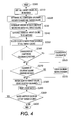
- Fig. 4 is a flowchart outlining one exemplary embodiment of this operation. Beginning in step S200, operation continues to step S210, where all target colours which are to be matched are listed. These target colours may have been inputted via the keyboard 230. Then, in step S220, all component colorants needed to match the target colours are determined for each target colour. One method of doing this is found in Fig. 3, as discussed above. The steps set forth in Fig. 3 are discussed in greater detail in the incorporated '195 patent. This results in a determination of the target colour parameters and the colorants colour parameters required to match each target colours.
- step S230 the amount of each colorants needed to match each of the target colours is determined. This lists reflects all of the colorants, such as, for example, 12 of the 16 Pantene® colours, which will be needed to match all of the target colours. Operation then continues to step S240.
- step S240 the order of target colours to be matched is scheduled.
- step S250 a target colour to match is selected or obtained from the schedule of all target colours.
- the scheduling may be based on several factors, including for example, (1) the amount of each colorants needed to match all target colours; (2) a ranking of which colorants are used in target colour matches from use in the most target colour matches to use in the fewest target colour matches; (3) a ranking of the number of colorants needed for each target colour match from the largest number of colorants to the fewest number of colorants; and (4) a list of the fewest number of changeovers of colorants are needed to match all of the target colours.
- Print jobs which require the same customer-selected colour are grouped and scheduled together. Print jobs which require similar colours are grouped together and ordered so that new component colour concentrates can be added to the existing mixed colorants supply, without having to first empty the supply chamber 10. For example, a print job for a yellow ink colour will be processed before an orange ink colour, which may, for example, be followed by a red ink colour. By processing the print jobs in this order, for example, only red and/or magenta ink has to be added to make each colour change. In another exemplary print job sequence, a light blue ink print job will be processed before a dark blue ink print job, so that only dark blue and/or black concentrates, or the equivalent, have to be added to make the particular colour change.
- step S260 once a target colour to match has been selected, a determination is made whether a changeover of component colorants is needed. This decision is based on the number of colorants supply tanks 15A-15Z, and the number of colorants needed to match all of the target colours. If the number of colorants is the same as, or fewer than the number of supply tanks, then there should be no need for a colorants changeover. However, if the number of colorants is greater than the number of colorants supply tanks, then there will be a need for one or more colorants changeovers or for replacement of one or more of one or more of the supply dispensers 15A-15Z.
- step S265 If a changeover of component colorants is needed, control goes to step S265, where one or more component colorants containers are changed. Control then continues to step S270. If a changeover of component colorants is not needed, control jumps directly from step S260 to step S270.
- step S270 a determination is made whether cleaning of the colorants mixing system is needed. If the supply chamber 10 needs to be cleaned, control jumps to step S275. Otherwise, in step S270, if cleaning of the colorants mixing system is not needed, control jumps directly to step S280. In step S275, the supply chamber 10 is cleaned. This cleaning may also involve cleaning supply lines from component colorants containers to the supply chamber 10 and, where permanent component colorants containers are used as the dispensers 15, cleaning of one or more of the dispensers 15. When the cleaning of the colorants mixing system is completed, control goes to step S280.
- step S280 the selected target colour is matched with the selected colorants. Details of this matching are set forth in Fig. 3, and described above. Then, in step S290, once a colour match is made, the matched colour is printed by the print engine. Next, in step S300, a determination is made whether one or more target colours are on the list of target colours to be matched. If there are one or more such target colours, control jumps back to step S250, where a target colour is selected to match. If there are no more target colours to be matched, control goes to step S400, and the process ends.
- the controller 200 continuously monitors the colorants to see if they need to be replenished in terms of amounts of colorants in each supply tank 15A-Z, or amount and strength of colorants added to the supply reservoir 10, and replenishes the colorants as needed.
- the mixed colorants in the supply chamber 10 can be dumped into a waste container 70.
- the supply chamber 10 can be washed manually when the next customer-selected colour can not be made by adding another colorants to the current mixed colorants material in the supply chamber 10.
- the colour controller 200 automatically empties the supply chamber 10 by actuating the pump 60, for example, to divert flow from the recirculation hose 62 to the hose 66 leading to the waste container 70. After emptying the supply chamber 10 of any remaining colour concentrate mixture, the chamber is refilled by a supply of cleaning fluid.
- This cleaning fluid is circulated through the recirculation hose 62 and the supply hose 18 leading to the development station of the printer and back through the return hose 64.
- the pump 60 is again activated to draw the cleaning fluid into the waste container 70.
- the fluid in the waste container then may be, for example, cleaned and transferred to the cleaning fluid container (not shown).
- the cleaning is achieved by electrophoretic deposition and need not be complete in order to provide functionally useful cleaning solution. Cleaning might also be achieved by settling, filtration, or some combination of these methods.
- Pantone® 151 A target colour of Pantone® 151 was selected.
- Pantone® 151 is an orange which is outside the gamut of process colours (i.e., those made by overlapping halftone patterns of cyan, magenta, yellow, and/or black).
- the colour coordinates (L*a*b*) of both Pantone® 151U and 151C were measured from print samples in the Pantone® Colour Selector 1000/Uncoated and the Pantone® Colour Selector 1000/Coated colour matching guides.
- the target colour to be matched was chosen to be Pantone® 151U because our filter paper is closer in properties to Pantone's uncoated paper than to the coated paper. Comparison to the target colour led to selection of 70% Yellow, 30% Warm Red as an optimum match to Pantone 151.
Landscapes
- Physics & Mathematics (AREA)
- General Physics & Mathematics (AREA)
- Color Electrophotography (AREA)
- Inking, Control Or Cleaning Of Printing Machines (AREA)
- Color Image Communication Systems (AREA)
- Coloring (AREA)
Abstract
Description
- This invention relates to a development system for creating colour output images in a printing machine.
- The importance of customer-selected colour to high-end printing, results in the colour management systems for both Windows® and Macintosh® operating systems to provide processes for specifying customer-selected colours by number, and for passing this information to printers. Similarly, all major personal computer graphics software packages which can output colour information directed to preparing printing plates provide methods of specifying Pantone® colours.
- Currently, customer-selectable spot colour processing methods involve a human operator mixing customer-selected inks according to predetermined formulas, such as those provided by the Pantone® CMS.
- This invention provides systems and methods for efficiently scheduling colour matching of target colours to optimize the accuracy of colour matches, and for using a limited number of colorants containers to accurately match target colours using a number of colorants which exceeds the limited number of colorants containers accurately matching a number of target colours by integrating mixing of colorants similar to the Pantone® primaries with a computer colour controller and print engine.
- This invention separately provides a method of automating the mixing of component colours to match a customer-selected colour.
- This invention also includes methods for automating the emptying, cleaning, and refilling of the mixed colorants supply chamber when the customer-selected colour changes.
- The colour control computer program takes as an input a customer-selected colour, to be printed by the print engine and outputs signals to the ink mixing station which cause mixing of component colours to be mixed to make a mixed colour matching the customer-selected colour. The system may optionally include waste disposal and /or cleaning stations and may automatically empty and clean the mixed colorants supply chamber.
- The ink supply station provides a mixed colorants whose colour matches a customer-selected ink colour. A colour controller receives as an input a customer-specified colour. The colour controller directs the ink mixing station to mix component colours in specific amounts, resulting in the customer's specified colour.
- A particular embodiment in accordance with this invention will now be described with reference to the accompanying drawings; in which:-
- Fig. 1 is a simplified elevational view of a liquid-based printing apparatus, as would incorporate the system of this invention;
- Fig. 2 shows in greater detail one exemplary embodiment of the controller of Fig. 1;
- Fig. 3 is a flowchart outlining one exemplary embodiment of a process of colour matching a single target colour according to this invention; and
- Fig. 4 is a flowchart outlining one exemplary embodiment of a process for colour matching a number of different target colours according to this invention.
-
- One application of the computer-controlled mixing of customer-selected colour inks, can be accomplished according to this invention by a colour control system. A print command may be received from incoming print description, such as from an Adobeò Postscript image file. If the colour control system is an integral part of the print engine, the colour control system can be coordinated when scheduling print jobs, resulting in, minimizing wasted mixed colour inks contaminated during switching between different coloured inks.
- Inputs to the colour control system may include certain specifications or characteristics of a particular substrate onto which the colour will be printed. These inputs may be accomplished, for example, by selection from a list, properties sensed off-line, and/or by appropriate sensors within the print engine.
- The commands to the colorants mixing system direct the addition of as many components as necessary, in the specific amounts, to create the customer-selected colour. Adding individual components may be made, for example, by precisely actuating and deactuating one or more pumps, and/or opening and closing one or more valves to coordinate the time period for the added components.
- The commands to the colorants mixing system may be modified, for example, by feedback from sensors associated with the mixed colorants supply chamber and/or component of the supply containers and/or associated with other parts of the print engine.
- The feedback to the colour control system may include, both colour and non-colour proportions. Non-colour properties of the ink which effect its printability include temperature, pH, viscosity, specific gravity, solids concentration, charge density, conductivity, and/or the concentrations of individual components.
- The colour of the ink in the mixed colorants supply chamber may be measured optically.
- Systems and methods for using the colour of the mixed colorants as it appears or when applied onto a given substrate to adjust the component composition (including the specific components and the amounts of any component) is described in US-A-5,713,062.
- Colour sensors, suitable for measuring ink supply colour and ink layer colour, will normally measure transmission or reflectivity in at least three wavelengths or wavelength regions. Suitable sensors for measuring ink supply colour and ink layer colour include spectrophotometers and calorimeters.
- Fig. 1 shows one exemplary embodiment of a colorants mixing system in which the ink is liquid electrophoretic toner transported from a
supply reservoir 10 to a latent image on aphotoreceptor 101 by anapplicator 20. Thesupply reservoir 10 acts as a holding receptacle to provide a liquid developer comprising a liquid carrier, a charge director compound and toner material which, in the case of a customer selectable colour application of the present invention includes a blend of different colorants toner particles. A plurality ofreplaceable supply dispensers 15A-15Z, each containing a concentrated supply of toner particles and carrier liquid corresponding to a basic colour component in a colour matching system, are provided in association with theoperational supply reservoir 10 and coupled to theoperational supply reservoir 10 as will be described. - An exemplary developing
material applicator 20 includes ahousing 22, having anelongated aperture 24 extending along a longitudinal axis of thehousing 22 so as to be oriented transverse to the surface of thephotoreceptor 101, along the direction of travel of thephotoreceptor 101 as indicated by thearrow 102. Theelongated aperture 24 is coupled to aninlet port 26 which is further coupled to thesupply reservoir 10 by atransport conduit 18. Thetransport conduit 18 operates in conjunction with theaperture 24 to provide a travel path for liquid developing material transported from thesupply reservoir 10 and also to define a developing material application region in which the liquid developer can freely flow to contact the surface of thephotoreceptor 101 to develop the latent image on thephotoreceptor 101. Thus, liquid developing material is pumped or otherwise transported from thesupply reservoir 10 to theapplicator 20 through at least oneinlet port 26 such that the liquid developer flows out of theelongated aperture 24 and into contact with the surface of thephotoreceptor 101. - Slightly downstream of, and adjacent to, the
developer applicator 20, in the direction of movement of thephotoreceptor 101, is an electricallybiased developer roller 30. The peripheral surface of the electricallybiased developer roller 30 is situated in close proximity to the surface of thephotoreceptor 101. Thedeveloper roller 30 rotates in a direction opposite to the movement of thephotoreceptor 101 to apply a substantial shear force to the thin layer of liquid developer present in the area of the nip between the electrically-biased developer roller 30 and thephotoreceptor 101. The shear force is applied to minimize the thickness of the liquid developer on the surface thereof. - This shear force removes excess liquid developing material from the surface of the photoreceptor and transports this excess developing material in the direction of the
development station 20. The excess developing material eventually falls away from the rotating metering roll for collection in thechamber 10 or awaste sump 70. ADC power supply 35 is also provided to maintain an electrical bias on the electricallybiased developer roller 30 at a selected polarity and magnitude such that the image areas of the electrostatic latent image on the photoconductive surface will attract marking particles from the developing material for developing the electrostatic latent image. The electrophoretic development process minimizes the existence of marking particles in background regions and maximizes the deposit of marking particles in image areas on the photoreceptor. - The supply reservoir or
chamber 10 is also coupled by arecirculation hose 62 and a portion of asupply emptying hose 66 to apump 60. Thepump 60 operates, for example, to circulate the contents of thesupply chamber 10 through therecirculation hose 62, as necessary, to keep the contents of thesupply chamber 10 uniformly mixed. Additionally, for example, thepump 60 also draws the contents of thesupply chamber 10 into thesupply emptying hose 66, and, as necessary, may deposit the contents of thesupply chamber 10 into thewaste container 70. - In operation, liquid developing material is transported in the direction of the
photoreceptor 101 filling the gap between the surface of thephotoreceptor 101 and theliquid development station 20. As thephotoreceptor 101 moves in the direction of thearrow 102, a portion of the liquid developing material in contact with thephotoreceptor 101 moves with thephotoreceptor 101 toward thedeveloper roller 30, where marking particles in the liquid developer material are attracted to electrostatic latent image areas on thephotoreceptor 101. The electrically-biased developer roller 30 also removes excess liquid developing material adhering to the photoconductive surface of thephotoreceptor 101 and acts as a seal to prevent extraneous liquid developing material from being carried away by thephotoreceptor 101. - Generally, the liquid carrier medium is present in a large amount in a liquid developing material composition, and constitutes that percentage by weight of the developer not accounted for by the other components. The liquid medium is usually present in an amount of from about 80% to 99.5% by weight, although this amount may vary from this range provided that the objectives of this invention can be achieved.
- This present invention, however, contemplates a developing material replenishing system capable of systematically replenishing individual colour components making up a customer-selectable colour developing material composition. As such, the replenishment system of the present invention includes the plurality of differently coloured
concentrate supply dispensers operative supply reservoir 10 via an associatedvalve member supply dispensers 15A-15Z contains a developing material concentrate of the known basic or primary colour component used in a given colour matching system. It will be understood that each of the plurality ofsupply dispensers 15A-15Z may be coupled to thesupply reservoir 10, or only selected supply dispensers may be coupled to thesupply chamber 10. For example, under certain circumstances, such as space constraints or cost restraints, it may be desirable to use onlydispensers - A colour control system using a
controller 200 as a component of the developer colour mixing and control system of this invention determines appropriate amounts of each colour liquid developer in eachsupply container 15A-15Z, to be added to thesupply chamber 10, and to make other determinations and control various functions, as discussed in more detail, below. - The
supply chamber 10 also contains at least three sensors or sensing devices. In various exemplary embodiments, the at least three sensors include afloat sensor 12, aconductivity sensor 14 and acolour sensor 42. Thefloat sensor 12 operates in relationship to a predetermined fill level "A". The placement of fill level A, may be, for example, fixed within thesupply chamber 10, or may be adjustable to any vertical placement within thesupply chamber 10. Thefloat sensor 12 is electronically coupled to thecontroller 200, and will communicate when thefloat sensor 12 drops below or rises above the predetermined level A, or to communicate the sensed fill level accordingly. Theconductivity sensor 14 is also electronically coupled to thecontroller 200, and will communicate when theconductivity sensor 14 drops below or rises above a predetermined level, or to communicate the sensed conductivity accordingly. Thecolour sensor 42 is also electronically coupled to thecontroller 200, and will communicate a sensed optical density, and/or a sensed colour to thecontroller 200. - The
controller 200 controllably directs the filling, emptying, cleaning and/or replacing of thesupply dispensers 15A-15Z for amounts of components into thesupply chamber 10. Thecontroller 200 also directs uniform mixing of components in thesupply chamber 10, and supply of the colorants mixed in thesupply chamber 10 to the printer, and/or returning unused ink from the printer to thesupply chamber 10. The ink mixing system may further contain sensors, such as those described above, which provide information to the colour control system. - In order to change from one mixed colour to another, the
supply chamber 10 may be drained, and flushed with a cleaning solution (which may be another colorants or diluent) if necessary or desired. Cleaning of thesupply chamber 10 and any associated lines connected to thesupply chamber 10, may be required or desired so that residual mixed colorants does not contaminate or react with a replacement colorants. - Then colorants may be added to the
supply chamber 10 to form the next customer-selected colour in the supply chamber orreservoir 10. Emptying and cleaning of thesupply dispensers 15A-15Z or of the supply chamber orreservoir 10 may be, for example, performed manually, after an ink supply dispenser 15 has been removed from the colorants mixing system. In various exemplary embodiments, this invention may include, for example, replaceable and/or disposable colorants supplychambers 15A-15Z used to deliver inks for an ink jet print engine. Thesupply chamber 10 may be in the form of a replaceable cartridge. The colorants supplychambers 15A-15Z may be discarded and replaced by other colorants supply chambers 15 or cartridges 15. - It may be preferable to automate cleaning by including a waste container and a cleaning station as part of the colour mixing system. Additionally, with powder or other dry inks, diverter blades or rolls may be used, for example, to move the waste mixed colorants powder to a waste container from the
supply chamber 10 and/or the associated colour print station of the print engine. - With liquid inks, a cleaning station may be provided, for example, with a cleaning fluid, which is used to wash the unused mixed colorants out of the
supply chambers 10 and/or the associated colour print station. When used with a liquid ink system, thewaste container 70 may be, for example, connected to the cleaning fluid container to clean the pigmented solids and/or other components from the waste liquid ink. In a liquid ink system, with awaste container 70 and cleaning fluid containers (not shown) interconnected, thecontroller 200 of thecolour control system 100 also controls valves that empty ink from thesupply chamber 10 into thewaste container 70 and refill thesupply chamber 10 with cleaning fluid. Adding components to make the next mixed colorants having the next customer-selected colour can be controlled by any of the conversion methods described below. - The colour mixing system can also allow one or more of the
component supply dispensers 15A-15Z to be replaced with different component supply dispensers 15. This allows the range of mixable colours to be increased without increasing the complexity of the ink transport system, but may require the ink transport system to be at least partially cleaned or flushed after one component supply dispenser 15 is connected to the colour mixing system. Fig. 1 shows an exemplary apparatus for developing an electrostatic latent image, using liquid developing materials, which is described in detail, herein. - The developer unit shown in Fig. 1 represents only one of various known developer devices that can be used to apply liquid developing material to the photoconductive surface.
- In one specific embodiment, the replenishment system includes sixteen supply dispensers, wherein each supply dispenser provides a different base colour developing material corresponding to the sixteen basic or constituent colours of the Pantone® Colour Matching System, such that colour formulations conveniently provided thereby can be utilized to produce over a thousand desirable colours and shades and a customer-selectable colour printing environment. The replenishment colours, also known as colour concentrates, include both a transparent white, which is usable to produce lighter colours on white substrates or transparencies without halftoning or reducing developed mass per unit area (DMA) and an opaque white.
- The mixed colorants is made from carrier fluid, charge director solution, and one or more component colour materials. The component colour materials have higher solids concentrations, generally 10-50% by weight, than the mixed colorants to be supplied to the printer. Similarly, the charge director solution has higher charge director solids concentration, generally 1-10% by weight, than is present in the mixed colorants which is supplied to the printer. The system adds carrier, charge director solution, and one to four component colour concentrates to the
supply chamber 10, as directed by thecolour controller 200. Using this system, as few as two different colour component materials, such as from one or more fromsupply dispensers supply chamber 10 to expand the colour gamut of the customer-selectable colours far beyond the colours available via halftone imaging techniques or even the colours available from mixing just yellow, magenta, cyan and black colour developing materials. - Since different components of the blended or mixed developing material in
supply chamber 10 may develop at different rates, thecontroller 200 determines appropriate amounts of each colour developing material in thecomponent supply dispensers supply chamber 10. Thecontroller 200 controllably operates each of thevalves 16A-16Z to supply appropriate amounts of one or more of the different colorants developing material contained in thecomponent supply dispensers 15A-15Z. - The
controller 200 may be directly connected to the printer's print engine control program, which may accept an input image and identifies the custom colour which the customer has specified. The custom colour may be specified as a coordinate-based number from the Pantone® CMS to thecolour controller 200 via akeyboard 230 or atouch screen 240, shown in Fig. 2. Thecolour controller 200 contains a colour look-up table, which may be located in aROM portion 271 or aRAM portion 272 of thememory 270. For each coordinate-based number in the Pantone® CMS, the colour look-up table includes an entry that has fields for one or more of (1) a list of component colour concentrates to be used, (2) a volume of each component colour concentrate to add to thesupply chamber 10 when the ink supply chamber is to be filled by a new mixed colour, (3) a carrier fluid volume to add when thesupply chamber 10 is to be filled by a new mixed colour, (4) a charge director concentrate volume to add when thesupply chamber 10 is to be filled by a new mixed colour, (5) a volume of each component colour concentrate to add when the overall optical density of the ink supply drops below a predetermined lower level, (6) a measure of the target colour to be matched, e.g., its transmission spectrum or its reflection spectrum, by the mixed colour, and/or (7) a set of characteristics of the component colours, e.g., their absorption spectra. - The absorption spectra for the component colours are measured and controlled in the process used to manufacture the component colour concentrates. The volume of each component colour concentrate to add to the
supply chamber 10 may be, for example, determined empirically for each customer-selectable colour, by printing different mixtures of the component colours onto the paper or other final substrate used in this printer. An additional amount of each component colour concentrate required to add when the overall optical density of the ink supply drops below the predetermined lower level may be also determined empirically, by coating the paper with different amounts of the component colours. In this way, thesupply chamber 10 is constantly replenished by component colours in exactly the ratios that are being printed onto a particular substrate. Because there is the possibility that slight errors in the replenishment could lead to a slow drift of component concentrations during very long print runs, the colour of the toner supply is measured, e.g., by its transmission spectrum, and compared to the target colour throughout the print run. The same colour correction methods that are used to prepare the initial mix of primaries can be used to correct the mix during printing. - The difference between the target and actual transmission spectra may be, for example, determined and combined with the absorption spectra to calculate the concentrations of each component colour in a particular quantity mixed toner.
- Fig. 3 is a flowchart outlining one exemplary embodiment of a method for producing a colour match of a single target colour according to this invention. Fig. 3 is fully described in US-A-6,052,195. The method outlined in Fig. 3 is used in the systems and methods of this invention to both determine which colorants are needed to match all of the target colours selected by a user such as, for example, a customer, and to provide a match for all of the target colours. These steps will be outlined below.
- Beginning in step S500, operation continues to step S510 where the transmission spectra of a target colour is determined. For example, the transmission spectra may be measured using a recording spectrophotometer, or obtained from memory, or downloaded from the Internet or other source. If the target spectrum is measured, it is beneficial to also store the target spectrum in memory. Next, in step S511, feed forward control is used to adjust the baseline proportions based on the measured or retrieved target spectra. Then, in step S512, target colour spectra are converted to absorption spectra. Operator then continues to step S514.
- In step S514, the target absorption spectrum is transferred from a spectral space to a control parameter space. Details of this transfer are set forth in the incorporated '195 patent. Alternatively, the process steps of S510, S512 and S514 can be combined into a single step, as set forth in the incorporated '195 patent.
- In steps S516-S520, the output spectrum is measured and converted to an absorption spectrum A, which is then transformed into measured control parameters, similarly to steps S510-S514. Operation then continues to step S522.
- In step S522, the control parameters describing the output colour are compared to the control parameters describing the target colour. Specifically, an error E representing the difference between the parameters describing the output colour and the parameters describing the target colour is determined. Operation then continues to step S524.
- In step S524, the incremental proportions by which each constituent colour must be adjusted are computed as set forth in the '195 patent. Operation then continues to step S526.
- In step S526, the incremental proportions are evaluated to ensure all appropriate boundary conditions are satisfied. The proportion adjustment values are then determined. In determining which colorants are needed to match all target colours, the proportion adjustment values need not be transmitted to the
supply chamber 10. However, to actually match a target colour, the proportion adjustment values are transmitted to thesupply chamber 10. - Then, in step S528, the process outlined in steps S516-526 is iterated until convergence occurs.
- Then, in step S530, signals representing the adjustments to be made to the proportions of the colorants are stored in a list of colorants needed to match a particular target colour. When determining the component colours needed to match all of the target colours, step S530 need not be repeated or may be repeated a predetermined minimal number of times. When making an actual colour match, the adjustment signals are sent by the
controller 200 to the colorants mixing valves to mix the selected colorants in the proper proportions to make a colour match. - The colour control computer program is used to schedule jobs in an order related to the customer-selected colours the scheduled jobs require.
- Fig. 4 is a flowchart outlining one exemplary embodiment of this operation. Beginning in step S200, operation continues to step S210, where all target colours which are to be matched are listed. These target colours may have been inputted via the
keyboard 230. Then, in step S220, all component colorants needed to match the target colours are determined for each target colour. One method of doing this is found in Fig. 3, as discussed above. The steps set forth in Fig. 3 are discussed in greater detail in the incorporated '195 patent. This results in a determination of the target colour parameters and the colorants colour parameters required to match each target colours. - Next, in step S230, the amount of each colorants needed to match each of the target colours is determined. This lists reflects all of the colorants, such as, for example, 12 of the 16 Pantene® colours, which will be needed to match all of the target colours. Operation then continues to step S240.
- In step S240, the order of target colours to be matched is scheduled. Next, in step S250, a target colour to match is selected or obtained from the schedule of all target colours. The scheduling may be based on several factors, including for example, (1) the amount of each colorants needed to match all target colours; (2) a ranking of which colorants are used in target colour matches from use in the most target colour matches to use in the fewest target colour matches; (3) a ranking of the number of colorants needed for each target colour match from the largest number of colorants to the fewest number of colorants; and (4) a list of the fewest number of changeovers of colorants are needed to match all of the target colours.
- Print jobs which require the same customer-selected colour are grouped and scheduled together. Print jobs which require similar colours are grouped together and ordered so that new component colour concentrates can be added to the existing mixed colorants supply, without having to first empty the
supply chamber 10. For example, a print job for a yellow ink colour will be processed before an orange ink colour, which may, for example, be followed by a red ink colour. By processing the print jobs in this order, for example, only red and/or magenta ink has to be added to make each colour change. In another exemplary print job sequence, a light blue ink print job will be processed before a dark blue ink print job, so that only dark blue and/or black concentrates, or the equivalent, have to be added to make the particular colour change. - Then, in step S260, once a target colour to match has been selected, a determination is made whether a changeover of component colorants is needed. This decision is based on the number of
colorants supply tanks 15A-15Z, and the number of colorants needed to match all of the target colours. If the number of colorants is the same as, or fewer than the number of supply tanks, then there should be no need for a colorants changeover. However, if the number of colorants is greater than the number of colorants supply tanks, then there will be a need for one or more colorants changeovers or for replacement of one or more of one or more of thesupply dispensers 15A-15Z. - If a changeover of component colorants is needed, control goes to step S265, where one or more component colorants containers are changed. Control then continues to step S270. If a changeover of component colorants is not needed, control jumps directly from step S260 to step S270.
- In step S270, a determination is made whether cleaning of the colorants mixing system is needed. If the
supply chamber 10 needs to be cleaned, control jumps to step S275. Otherwise, in step S270, if cleaning of the colorants mixing system is not needed, control jumps directly to step S280. In step S275, thesupply chamber 10 is cleaned. This cleaning may also involve cleaning supply lines from component colorants containers to thesupply chamber 10 and, where permanent component colorants containers are used as the dispensers 15, cleaning of one or more of the dispensers 15. When the cleaning of the colorants mixing system is completed, control goes to step S280. - In step S280, the selected target colour is matched with the selected colorants. Details of this matching are set forth in Fig. 3, and described above. Then, in step S290, once a colour match is made, the matched colour is printed by the print engine. Next, in step S300, a determination is made whether one or more target colours are on the list of target colours to be matched. If there are one or more such target colours, control jumps back to step S250, where a target colour is selected to match. If there are no more target colours to be matched, control goes to step S400, and the process ends.
- The
controller 200 continuously monitors the colorants to see if they need to be replenished in terms of amounts of colorants in eachsupply tank 15A-Z, or amount and strength of colorants added to thesupply reservoir 10, and replenishes the colorants as needed. - It is possible to remove the
supply chamber 10 and to save its contents until the same colour is again selected. Alternatively, the mixed colorants in thesupply chamber 10 can be dumped into awaste container 70. Thesupply chamber 10 can be washed manually when the next customer-selected colour can not be made by adding another colorants to the current mixed colorants material in thesupply chamber 10. In this exemplary embodiment, however, thecolour controller 200 automatically empties thesupply chamber 10 by actuating thepump 60, for example, to divert flow from therecirculation hose 62 to thehose 66 leading to thewaste container 70. After emptying thesupply chamber 10 of any remaining colour concentrate mixture, the chamber is refilled by a supply of cleaning fluid. This cleaning fluid is circulated through therecirculation hose 62 and thesupply hose 18 leading to the development station of the printer and back through thereturn hose 64. After a predetermined cleaning period, thepump 60 is again activated to draw the cleaning fluid into thewaste container 70. The fluid in the waste container then may be, for example, cleaned and transferred to the cleaning fluid container (not shown). The cleaning is achieved by electrophoretic deposition and need not be complete in order to provide functionally useful cleaning solution. Cleaning might also be achieved by settling, filtration, or some combination of these methods. - A simple method of predetermining mixing ratios corresponding to a target colour is shown to demonstrate substrate effects on the final printed colour. A target colour of Pantone® 151 was selected. Pantone® 151 is an orange which is outside the gamut of process colours (i.e., those made by overlapping halftone patterns of cyan, magenta, yellow, and/or black). The colour coordinates (L*a*b*) of both Pantone® 151U and 151C were measured from print samples in the Pantone® Colour Selector 1000/Uncoated and the Pantone® Colour Selector 1000/Coated colour matching guides.
- Filtration was used as the method to predetermine the proportions of Yellow and Warm Red liquid xerographic inks necessary to match Pantone® 151 (an orange). Yellow and Warm Red inks were each diluted to 0.00192 wt % toner solids, for uniform filtration. The target total developed mass per area (DMA) was 0.1 mg2/cm on a filtration area of 10 cm2. A number of 50 gram samples were prepared by mixing the two toners in proportions shown below. 1.0 mg of each mixture was deposited on a filter paper by filtration. After filtration, each sample was dried and fused in a warm oven for about 30 minutes. After cooling, the colour of each sample was measured. The target colour to be matched was chosen to be Pantone® 151U because our filter paper is closer in properties to Pantone's uncoated paper than to the coated paper. Comparison to the target colour led to selection of 70% Yellow, 30% Warm Red as an optimum match to Pantone 151.
%Yellow (mass) %Warm Red (grams) L* a* b* 80% (40.020 g) 20% (9.992 g) 75.5 33.20 75.60 75% (37.708 g) 25% (12.512 g) 73.52 37.62 71.48 70% (34.967 g) 30% (14.993 g) 69.95 45.99 71.86 Target colour Pantone® 151U 68.87 43.27 53.49 Pantone® 151C 64.34 50.01 80.88 - Yellow and Warm Red liquid xerographic inks were then mixed in the predetermined 70/30 ratio and added to a Xerox ColourgrafX 8936 printer. This mixed colorants was printed onto Xerox ColourgrafX 6262 dielectric paper. This paper is smooth and coated, but significantly less glossy than the paper used in the Pantone® Colour Selector 1000/Coated. The printed colour was
L* a* b* DE from 151U 71.09 40.44 52.28 3.79 - Because of the differences between the filter paper, dielectric paper actually used, and the paper used in Pantone® Colour Selector 1000/Coated, this is actually a better match than was achieved with the filtrations. After lamination, the printed colour measured
L* a* b* DE from 151U 66.31 43.84 53.75 2.63 - Thus, even laminating to increase gloss does not bring the printed colour closer to Pantone® 151C than to Pantone® 151U. This shows the need for careful empirical relations between substrate properties, ink colour, and the final printed colour.
- The following numbered clauses disclose various combinations of features:
- 1. A method of colour matching using colorants
supplied to a print engine having a colorant mixing station
and at least one colorant supply chamber, comprising:
- listing a plurality of target colours to be matched;
- listing the colorants needed to match the target colours;
- determining the amounts of each colorants needed to make each target colour;
- selecting colorants to match each scheduled target colour;
- mixing the selected colorants; and
- controllably integrating the previous steps to supply the mixture to the print engine.
- 2. A method of colour matching using colorants
supplied to a print engine having a colorant mixing station
and at least one colorant supply chamber, comprising:
- listing a plurality of target colours to be matched;
- determining colour characteristics of a target coloured medium to be matched by colorants supplied to the print engine;
- converting the determined colour characteristics of the target coloured medium to colour characteristics of a matching coloured medium using the supplied colorants;
- listing the colorants needed to match the target colours;
- determining colour characteristics of a target-coloured medium to be matched by colorants supplied to the print engine;
- determining the amounts of each colorant needed to make each target colour;
- selecting colorants to match a first scheduled target colour;
- mixing the selected colorants; and
- controllably integrating the previous steps to supply the mixture to the print engine.
- 3. A method of colour matching using colorants
supplied to a print engine having a colorant mixing station
and at least one colorant supply chamber, comprising:
- listing a plurality of target colours to be matched;
- converting the determined colour characteristics of the target coloured medium to colour characteristics of a matching coloured medium using the supplied colorants;
- listing the colorants needed to match the target colours;
- determining the amounts of each colorant needed to make each target colour;
- selecting colorants to match a first scheduled target colour;
- mixing the selected colorants; and
- controllably integrating the previous steps to supply the mixture to the print engine.
- 4. A method of colour matching using colorants
supplied to a print engine having a colorant mixing station
and at least one colorant supply chamber, comprising:
- listing a plurality of target colours to be matched;
- listing the colorants needed to match the target colours;
- determining the amounts of each colorants needed to make each target colour;
- determining a schedule of target colours to be matched.
- selecting colorants to match each scheduled target colour;
- mixing the selected colorants; and
- controllably integrating the previous steps to supply the mixture to the print engine.
-
Claims (4)
- A method of colour matching using colorants supplied to a print engine having a colorant mixing station and at least one colorant supply chamber, comprising:listing a plurality of target colours to be matched;listing the colorants needed to match the target colours;determining the amounts of each colorants needed to make each target colour;selecting colorants to match each scheduled target colour;mixing the selected colorants; andcontrollably integrating the previous steps to supply the mixture to the print engine.
- A method of colour matching using colorants supplied to a print engine having a colorant mixing station and at least one colorant supply chamber, comprising:listing a plurality of target colours to be matched;determining colour characteristics of a target coloured medium to be matched by colorants supplied to the print engine;converting the determined colour characteristics of the target coloured medium to colour characteristics of a matching coloured medium using the supplied colorants;listing the colorants needed to match the target colours;determining colour characteristics of a target-coloured medium to be matched by colorants supplied to the print engine;determining the amounts of each colorant needed to make each target colour;selecting colorants to match a first scheduled target colour;mixing the selected colorants; andcontrollably integrating the previous steps to supply the mixture to the print engine.
- A method of colour matching using colorants supplied to a print engine having a colorant mixing station and at least one colorant supply chamber, comprising:listing a plurality of target colours to be matched;converting the determined colour characteristics of the target coloured medium to colour characteristics of a matching coloured medium using the supplied colorants;listing the colorants needed to match the target colours;determining the amounts of each colorant needed to make each target colour;selecting colorants to match a first scheduled target colour;mixing the selected colorants; andcontrollably integrating the previous steps to supply the mixture to the print engine.
- A method of colour matching using colorants supplied to a print engine having a colorant mixing station and at least one colorant supply chamber, comprising:listing a plurality of target colours to be matched;listing the colorants needed to match the target colours;determining the amounts of each colorants needed to make each target colour;determining a schedule of target colours to be matched.selecting colorants to match each scheduled target colour;mixing the selected colorants; andcontrollably integrating the previous steps to supply the mixture to the print engine.
Applications Claiming Priority (2)
| Application Number | Priority Date | Filing Date | Title |
|---|---|---|---|
| US09/986,101 US6575096B1 (en) | 2001-11-07 | 2001-11-07 | Computer controlled mixing of customer-selected color inks for printing machines |
| US986101 | 2001-11-07 |
Publications (3)
| Publication Number | Publication Date |
|---|---|
| EP1310833A2 true EP1310833A2 (en) | 2003-05-14 |
| EP1310833A3 EP1310833A3 (en) | 2004-06-02 |
| EP1310833B1 EP1310833B1 (en) | 2007-09-19 |
Family
ID=25532081
Family Applications (1)
| Application Number | Title | Priority Date | Filing Date |
|---|---|---|---|
| EP02257534A Expired - Lifetime EP1310833B1 (en) | 2001-11-07 | 2002-10-30 | Method of mixing colour inks for printing |
Country Status (5)
| Country | Link |
|---|---|
| US (1) | US6575096B1 (en) |
| EP (1) | EP1310833B1 (en) |
| JP (1) | JP4374178B2 (en) |
| BR (1) | BR0204577A (en) |
| DE (1) | DE60222520T2 (en) |
Cited By (2)
| Publication number | Priority date | Publication date | Assignee | Title |
|---|---|---|---|---|
| WO2007082791A1 (en) * | 2006-01-12 | 2007-07-26 | OCé PRINTING SYSTEMS GMBH | Method for developing potential images which are produced on an intermediate image carrier of images which are to be printed having selectable customer-specific colours in an electrographic printing or copying device |
| WO2022090056A1 (en) | 2020-10-28 | 2022-05-05 | Bobst Bielefeld Gmbh | Printing system |
Families Citing this family (34)
| Publication number | Priority date | Publication date | Assignee | Title |
|---|---|---|---|---|
| JP2003078778A (en) * | 2001-09-04 | 2003-03-14 | Fuji Photo Film Co Ltd | Image converter and image conversion program |
| DE10209856B4 (en) * | 2002-03-06 | 2007-09-20 | Man Roland Druckmaschinen Ag | Method for controlling the introduction of cleaning fluid |
| US20030204410A1 (en) * | 2002-04-26 | 2003-10-30 | Clariant International, Ltd. | Method and apparatus for approving color samples |
| US7623704B2 (en) * | 2003-01-31 | 2009-11-24 | Fuji Xerox Co. Ltd. | Color processing method, color processing apparatus, and storage medium |
| DE10333625B4 (en) * | 2003-07-24 | 2009-04-02 | Gunther Prof. Dr.-Ing. Krieg | Method and device for measuring and controlling the concentration of chemical compounds in fountain solution during offset printing |
| JP2005310115A (en) * | 2004-03-25 | 2005-11-04 | Fuji Photo Film Co Ltd | Image data converter, image data conversion program, and image output system |
| US7630540B2 (en) * | 2004-11-12 | 2009-12-08 | Riso Kagaku Corporation | Image processing device and printer driver converting multivalued pixel values using a color conversion LUT |
| CA2492961C (en) * | 2004-12-23 | 2010-03-23 | Chris Frosztega | Colour coatings blender apparatus, production of colour coatings gradients and application methods and uses therefor |
| KR100618390B1 (en) * | 2005-01-13 | 2006-08-31 | 삼성전자주식회사 | Developer amount control apparatus for developing roller, image forming apparatus having the same, and control method thereof |
| JP4380602B2 (en) * | 2005-07-27 | 2009-12-09 | キヤノン株式会社 | Image forming apparatus and control method thereof |
| US20070048020A1 (en) * | 2005-08-23 | 2007-03-01 | Xerox Corporation | Color order fulfilment method |
| JP5151024B2 (en) * | 2005-11-22 | 2013-02-27 | 富士ゼロックス株式会社 | Printing support apparatus, printing apparatus, printing support method, and printing support program |
| US8078071B2 (en) * | 2006-02-03 | 2011-12-13 | Canon Kabushiki Kaisha | Image forming apparatus and control method of the image forming apparatus |
| DE102007005018B4 (en) * | 2006-02-24 | 2020-06-04 | Heidelberger Druckmaschinen Ag | Process for the color control of copies of a printing press |
| US7650089B2 (en) * | 2006-11-13 | 2010-01-19 | Xerox Corporation | System for measuring and controlling total color of a mixture of colorants such as toner |
| PL2219870T3 (en) * | 2007-12-06 | 2012-02-29 | Windmoeller & Hoelscher | Colour-management |
| US8351100B2 (en) * | 2008-05-28 | 2013-01-08 | Xerox Corporation | Method to create spot colors with white and CMYK toner and achieve color consistency |
| US8065913B2 (en) * | 2008-09-30 | 2011-11-29 | Xerox Corporation | Ink level sensor |
| US8057008B2 (en) * | 2008-10-01 | 2011-11-15 | Xerox Corporation | Ink conductivity fault tolerant mode |
| US8042895B2 (en) * | 2008-10-31 | 2011-10-25 | Xerox Corporation | Ink conductivity recovery method for an imaging device |
| EP2193919A1 (en) * | 2008-12-02 | 2010-06-09 | Fischer & Krecke GmbH | Method of color setting in a rotary printing press |
| JP2010256329A (en) * | 2009-04-03 | 2010-11-11 | Seiko Epson Corp | Measurement of light transmittance in printed materials |
| US8144319B2 (en) | 2009-05-07 | 2012-03-27 | Solum, Inc. | Automated soil measurement device |
| US8839716B2 (en) * | 2011-03-04 | 2014-09-23 | The Procter & Gamble Company | Apparatus for applying indicia having a large color gamut on web substrates |
| US8839717B2 (en) * | 2011-03-04 | 2014-09-23 | The Procter & Gamble Company | Unique process for printing multiple color indicia upon web substrates |
| US8833250B2 (en) | 2011-03-04 | 2014-09-16 | The Procter & Gamble Company | Apparatus for applying indicia having a large color gamut on web substrates |
| US8985013B2 (en) * | 2011-03-04 | 2015-03-24 | The Procter & Gamble Company | Apparatus for applying indicia having a large color gamut on web substrates |
| US9146223B1 (en) | 2012-08-03 | 2015-09-29 | Monsanto Technology Llc | Automated soil measurement device |
| US9291545B1 (en) | 2012-09-06 | 2016-03-22 | Monsanto Technology Llc | Self-filling soil processing chamber with dynamic extractant volume |
| JP6217526B2 (en) * | 2014-05-23 | 2017-10-25 | 京セラドキュメントソリューションズ株式会社 | Image forming apparatus and image forming control method |
| DE102014110598A1 (en) * | 2014-07-28 | 2016-01-28 | Océ Printing Systems GmbH & Co. KG | Process for coloring products |
| KR102307599B1 (en) * | 2015-03-16 | 2021-10-05 | 엘지전자 주식회사 | Printing apparatus for building three-dimensional object |
| WO2017152116A1 (en) * | 2016-03-04 | 2017-09-08 | Quad/Tech, Inc. | System and method for rapid press changeover with sensed ink characteristic |
| DE102018211601A1 (en) * | 2018-07-12 | 2020-01-16 | Heidelberger Druckmaschinen Ag | Process for cleaning the surface of at least one rotatable component of a printing press from a printing fluid |
Citations (2)
| Publication number | Priority date | Publication date | Assignee | Title |
|---|---|---|---|---|
| US5713062A (en) | 1996-09-26 | 1998-01-27 | Xerox Corporation | Color mixing and control system for use in an electrostatographic printing machine |
| US6052195A (en) | 1998-05-22 | 2000-04-18 | Xerox Corporation | Automatic colorant mixing method and apparatus |
Family Cites Families (9)
| Publication number | Priority date | Publication date | Assignee | Title |
|---|---|---|---|---|
| US3357402A (en) | 1966-12-27 | 1967-12-12 | Xerox Corp | Rotary brush development |
| US4403866A (en) * | 1982-05-07 | 1983-09-13 | E. I. Du Pont De Nemours And Company | Process for making paints |
| US4733273A (en) | 1986-07-01 | 1988-03-22 | Xerox Corporation | Liquid developing apparatus |
| US4883018A (en) | 1988-10-28 | 1989-11-28 | Xerox Corporation | Liquid ink development system |
| US5270702A (en) | 1990-06-04 | 1993-12-14 | Motorola, Inc. | Battery door for a selective call receiver |
| US5355201A (en) | 1993-07-21 | 1994-10-11 | Xerox Corporation | Liquid development system |
| US5604567A (en) * | 1994-06-03 | 1997-02-18 | Xerox Corporation | Printer color and gray balance adjustment system |
| US5899605A (en) | 1996-09-26 | 1999-05-04 | Xerox Corporation | Color mixing and color system for use in a printing machine |
| US5897239A (en) | 1997-03-31 | 1999-04-27 | Xerox Corporation | Photometric color correction and control system for custom colors |
-
2001
- 2001-11-07 US US09/986,101 patent/US6575096B1/en not_active Expired - Fee Related
-
2002
- 2002-10-30 EP EP02257534A patent/EP1310833B1/en not_active Expired - Lifetime
- 2002-10-30 DE DE60222520T patent/DE60222520T2/en not_active Expired - Lifetime
- 2002-10-31 JP JP2002317114A patent/JP4374178B2/en not_active Expired - Fee Related
- 2002-10-31 BR BR0204577-0A patent/BR0204577A/en not_active Application Discontinuation
Patent Citations (2)
| Publication number | Priority date | Publication date | Assignee | Title |
|---|---|---|---|---|
| US5713062A (en) | 1996-09-26 | 1998-01-27 | Xerox Corporation | Color mixing and control system for use in an electrostatographic printing machine |
| US6052195A (en) | 1998-05-22 | 2000-04-18 | Xerox Corporation | Automatic colorant mixing method and apparatus |
Cited By (3)
| Publication number | Priority date | Publication date | Assignee | Title |
|---|---|---|---|---|
| WO2007082791A1 (en) * | 2006-01-12 | 2007-07-26 | OCé PRINTING SYSTEMS GMBH | Method for developing potential images which are produced on an intermediate image carrier of images which are to be printed having selectable customer-specific colours in an electrographic printing or copying device |
| WO2022090056A1 (en) | 2020-10-28 | 2022-05-05 | Bobst Bielefeld Gmbh | Printing system |
| US12397540B2 (en) | 2020-10-28 | 2025-08-26 | Bobst Bielefeld Gmbh | Printing system |
Also Published As
| Publication number | Publication date |
|---|---|
| DE60222520D1 (en) | 2007-10-31 |
| EP1310833A3 (en) | 2004-06-02 |
| JP2003182043A (en) | 2003-07-03 |
| BR0204577A (en) | 2003-09-16 |
| US6575096B1 (en) | 2003-06-10 |
| US20030097947A1 (en) | 2003-05-29 |
| EP1310833B1 (en) | 2007-09-19 |
| JP4374178B2 (en) | 2009-12-02 |
| DE60222520T2 (en) | 2008-06-19 |
Similar Documents
| Publication | Publication Date | Title |
|---|---|---|
| EP1310833B1 (en) | Method of mixing colour inks for printing | |
| US6938984B2 (en) | Custom color inkjet printing system | |
| US5899605A (en) | Color mixing and color system for use in a printing machine | |
| CN101231499A (en) | Powder filling method, powder container, developer replenishing device, developer replenishing method, and image forming apparatus | |
| JPH10104954A (en) | Developing system, developing device and printing method for electrostatic copying and printing machine | |
| EP1315049A2 (en) | Hybrid electrophotographic apparatus for custom color printing | |
| CN103676558B (en) | Developer replenishing apparatus and imaging device | |
| JPH11249376A (en) | Color material providing device | |
| US6776099B1 (en) | Central-ink supply system for multi-printer systems | |
| EP0834783B1 (en) | Liquid developing material replenishment system and method | |
| KR20010090481A (en) | Liquid developing device, Liquid developing method and Printer including the device | |
| EP1315048B1 (en) | Hybrid electrophotographic apparatus for custom color printing | |
| EP2230554B1 (en) | System and method for producing a dry toner associated with a selected gloss level | |
| CN100449418C (en) | Process cartridge and image forming apparatus using the same | |
| US20040091286A1 (en) | Method of development of custom colors without changing developer housing | |
| US20080310870A1 (en) | Method for Developing Potential Images Which are Produced on an Intermediate Image Carrier of Images Which are to be Printed Having Selectable Customer-Specific Colors in an Electrographic Printing or Copying Device | |
| US9904212B2 (en) | Toner agitation system including a cam driven reciprocating toner agitator | |
| EP2605914B1 (en) | Fluid delivery system and method thereof | |
| JP4121841B2 (en) | Developing device, custom color housing, and toner image forming method | |
| US6094547A (en) | Process controlled carrier dispensing | |
| EP0833219A1 (en) | Color mixing and control system for use in an electrostatographic printing machine | |
| EP0833220B1 (en) | Color mixing and control system for use in an electrostatographic printing machine | |
| US20070253744A1 (en) | Device and method for the replacement of expired developer | |
| US20040120732A1 (en) | Device and method for the replacement of out-of-date developer | |
| JPH09311533A (en) | Image forming device |
Legal Events
| Date | Code | Title | Description |
|---|---|---|---|
| PUAI | Public reference made under article 153(3) epc to a published international application that has entered the european phase |
Free format text: ORIGINAL CODE: 0009012 |
|
| AK | Designated contracting states |
Designated state(s): AT BE BG CH CY CZ DE DK EE ES FI FR GB GR IE IT LI LU MC NL PT SE SK TR |
|
| AX | Request for extension of the european patent |
Extension state: AL LT LV MK RO SI |
|
| PUAL | Search report despatched |
Free format text: ORIGINAL CODE: 0009013 |
|
| AK | Designated contracting states |
Kind code of ref document: A3 Designated state(s): AT BE BG CH CY CZ DE DK EE ES FI FR GB GR IE IT LI LU MC NL PT SE SK TR |
|
| AX | Request for extension of the european patent |
Extension state: AL LT LV MK RO SI |
|
| RIC1 | Information provided on ipc code assigned before grant |
Ipc: 7G 03G 15/01 A Ipc: 7G 03G 15/10 B |
|
| 17P | Request for examination filed |
Effective date: 20041202 |
|
| AKX | Designation fees paid |
Designated state(s): DE FR GB |
|
| 17Q | First examination report despatched |
Effective date: 20060602 |
|
| GRAP | Despatch of communication of intention to grant a patent |
Free format text: ORIGINAL CODE: EPIDOSNIGR1 |
|
| GRAC | Information related to communication of intention to grant a patent modified |
Free format text: ORIGINAL CODE: EPIDOSCIGR1 |
|
| GRAS | Grant fee paid |
Free format text: ORIGINAL CODE: EPIDOSNIGR3 |
|
| GRAA | (expected) grant |
Free format text: ORIGINAL CODE: 0009210 |
|
| AK | Designated contracting states |
Kind code of ref document: B1 Designated state(s): DE FR GB |
|
| REG | Reference to a national code |
Ref country code: GB Ref legal event code: FG4D |
|
| REF | Corresponds to: |
Ref document number: 60222520 Country of ref document: DE Date of ref document: 20071031 Kind code of ref document: P |
|
| ET | Fr: translation filed | ||
| PLBE | No opposition filed within time limit |
Free format text: ORIGINAL CODE: 0009261 |
|
| STAA | Information on the status of an ep patent application or granted ep patent |
Free format text: STATUS: NO OPPOSITION FILED WITHIN TIME LIMIT |
|
| 26N | No opposition filed |
Effective date: 20080620 |
|
| PGFP | Annual fee paid to national office [announced via postgrant information from national office to epo] |
Ref country code: GB Payment date: 20130923 Year of fee payment: 12 |
|
| PGFP | Annual fee paid to national office [announced via postgrant information from national office to epo] |
Ref country code: DE Payment date: 20130920 Year of fee payment: 12 Ref country code: FR Payment date: 20131028 Year of fee payment: 12 |
|
| REG | Reference to a national code |
Ref country code: DE Ref legal event code: R119 Ref document number: 60222520 Country of ref document: DE |
|
| GBPC | Gb: european patent ceased through non-payment of renewal fee |
Effective date: 20141030 |
|
| PG25 | Lapsed in a contracting state [announced via postgrant information from national office to epo] |
Ref country code: DE Free format text: LAPSE BECAUSE OF NON-PAYMENT OF DUE FEES Effective date: 20150501 Ref country code: GB Free format text: LAPSE BECAUSE OF NON-PAYMENT OF DUE FEES Effective date: 20141030 |
|
| REG | Reference to a national code |
Ref country code: FR Ref legal event code: ST Effective date: 20150630 |
|
| PG25 | Lapsed in a contracting state [announced via postgrant information from national office to epo] |
Ref country code: FR Free format text: LAPSE BECAUSE OF NON-PAYMENT OF DUE FEES Effective date: 20141031 |