EP1310821A2 - Liquid crystal display device and electronic apparatus - Google Patents
Liquid crystal display device and electronic apparatus Download PDFInfo
- Publication number
- EP1310821A2 EP1310821A2 EP02257408A EP02257408A EP1310821A2 EP 1310821 A2 EP1310821 A2 EP 1310821A2 EP 02257408 A EP02257408 A EP 02257408A EP 02257408 A EP02257408 A EP 02257408A EP 1310821 A2 EP1310821 A2 EP 1310821A2
- Authority
- EP
- European Patent Office
- Prior art keywords
- liquid crystal
- light
- films
- display device
- layer
- Prior art date
- Legal status (The legal status is an assumption and is not a legal conclusion. Google has not performed a legal analysis and makes no representation as to the accuracy of the status listed.)
- Granted
Links
- 239000004973 liquid crystal related substance Substances 0.000 title claims abstract description 195
- 239000004986 Cholesteric liquid crystals (ChLC) Substances 0.000 claims abstract description 137
- 239000000758 substrate Substances 0.000 claims abstract description 128
- 238000001228 spectrum Methods 0.000 claims description 30
- 230000010287 polarization Effects 0.000 claims description 25
- 238000000411 transmission spectrum Methods 0.000 claims description 19
- 210000002858 crystal cell Anatomy 0.000 claims description 15
- 230000000295 complement effect Effects 0.000 claims description 10
- 238000005286 illumination Methods 0.000 claims description 10
- 239000000049 pigment Substances 0.000 claims description 3
- 239000010408 film Substances 0.000 description 141
- 239000011295 pitch Substances 0.000 description 15
- 239000003086 colorant Substances 0.000 description 11
- 230000000694 effects Effects 0.000 description 6
- 230000005540 biological transmission Effects 0.000 description 5
- 239000004411 aluminium Substances 0.000 description 3
- 229910052782 aluminium Inorganic materials 0.000 description 3
- XAGFODPZIPBFFR-UHFFFAOYSA-N aluminium Chemical compound [Al] XAGFODPZIPBFFR-UHFFFAOYSA-N 0.000 description 3
- 230000010365 information processing Effects 0.000 description 3
- 238000002834 transmittance Methods 0.000 description 3
- 238000004804 winding Methods 0.000 description 3
- 239000004642 Polyimide Substances 0.000 description 2
- 230000001413 cellular effect Effects 0.000 description 2
- 230000003098 cholesteric effect Effects 0.000 description 2
- 238000010030 laminating Methods 0.000 description 2
- 239000000463 material Substances 0.000 description 2
- 239000011159 matrix material Substances 0.000 description 2
- 229910052751 metal Inorganic materials 0.000 description 2
- 239000002184 metal Substances 0.000 description 2
- 239000000203 mixture Substances 0.000 description 2
- 230000003287 optical effect Effects 0.000 description 2
- 238000001579 optical reflectometry Methods 0.000 description 2
- 229920001721 polyimide Polymers 0.000 description 2
- 238000002310 reflectometry Methods 0.000 description 2
- 239000011347 resin Substances 0.000 description 2
- 229920005989 resin Polymers 0.000 description 2
- 239000010409 thin film Substances 0.000 description 2
- BQCADISMDOOEFD-UHFFFAOYSA-N Silver Chemical compound [Ag] BQCADISMDOOEFD-UHFFFAOYSA-N 0.000 description 1
- 230000015572 biosynthetic process Effects 0.000 description 1
- 239000000470 constituent Substances 0.000 description 1
- 239000011521 glass Substances 0.000 description 1
- AMGQUBHHOARCQH-UHFFFAOYSA-N indium;oxotin Chemical compound [In].[Sn]=O AMGQUBHHOARCQH-UHFFFAOYSA-N 0.000 description 1
- 239000007788 liquid Substances 0.000 description 1
- 238000012986 modification Methods 0.000 description 1
- 230000004048 modification Effects 0.000 description 1
- 239000004033 plastic Substances 0.000 description 1
- 229920003023 plastic Polymers 0.000 description 1
- 239000004332 silver Substances 0.000 description 1
- 229910052709 silver Inorganic materials 0.000 description 1
- 230000007704 transition Effects 0.000 description 1
Images




Classifications
-
- G—PHYSICS
- G02—OPTICS
- G02F—OPTICAL DEVICES OR ARRANGEMENTS FOR THE CONTROL OF LIGHT BY MODIFICATION OF THE OPTICAL PROPERTIES OF THE MEDIA OF THE ELEMENTS INVOLVED THEREIN; NON-LINEAR OPTICS; FREQUENCY-CHANGING OF LIGHT; OPTICAL LOGIC ELEMENTS; OPTICAL ANALOGUE/DIGITAL CONVERTERS
- G02F1/00—Devices or arrangements for the control of the intensity, colour, phase, polarisation or direction of light arriving from an independent light source, e.g. switching, gating or modulating; Non-linear optics
- G02F1/01—Devices or arrangements for the control of the intensity, colour, phase, polarisation or direction of light arriving from an independent light source, e.g. switching, gating or modulating; Non-linear optics for the control of the intensity, phase, polarisation or colour
- G02F1/13—Devices or arrangements for the control of the intensity, colour, phase, polarisation or direction of light arriving from an independent light source, e.g. switching, gating or modulating; Non-linear optics for the control of the intensity, phase, polarisation or colour based on liquid crystals, e.g. single liquid crystal display cells
- G02F1/133—Constructional arrangements; Operation of liquid crystal cells; Circuit arrangements
- G02F1/1333—Constructional arrangements; Manufacturing methods
- G02F1/1335—Structural association of cells with optical devices, e.g. polarisers or reflectors
- G02F1/133528—Polarisers
- G02F1/133536—Reflective polarizers
-
- G—PHYSICS
- G02—OPTICS
- G02F—OPTICAL DEVICES OR ARRANGEMENTS FOR THE CONTROL OF LIGHT BY MODIFICATION OF THE OPTICAL PROPERTIES OF THE MEDIA OF THE ELEMENTS INVOLVED THEREIN; NON-LINEAR OPTICS; FREQUENCY-CHANGING OF LIGHT; OPTICAL LOGIC ELEMENTS; OPTICAL ANALOGUE/DIGITAL CONVERTERS
- G02F1/00—Devices or arrangements for the control of the intensity, colour, phase, polarisation or direction of light arriving from an independent light source, e.g. switching, gating or modulating; Non-linear optics
- G02F1/01—Devices or arrangements for the control of the intensity, colour, phase, polarisation or direction of light arriving from an independent light source, e.g. switching, gating or modulating; Non-linear optics for the control of the intensity, phase, polarisation or colour
- G02F1/13—Devices or arrangements for the control of the intensity, colour, phase, polarisation or direction of light arriving from an independent light source, e.g. switching, gating or modulating; Non-linear optics for the control of the intensity, phase, polarisation or colour based on liquid crystals, e.g. single liquid crystal display cells
- G02F1/133—Constructional arrangements; Operation of liquid crystal cells; Circuit arrangements
- G02F1/1333—Constructional arrangements; Manufacturing methods
- G02F1/1335—Structural association of cells with optical devices, e.g. polarisers or reflectors
-
- G—PHYSICS
- G02—OPTICS
- G02F—OPTICAL DEVICES OR ARRANGEMENTS FOR THE CONTROL OF LIGHT BY MODIFICATION OF THE OPTICAL PROPERTIES OF THE MEDIA OF THE ELEMENTS INVOLVED THEREIN; NON-LINEAR OPTICS; FREQUENCY-CHANGING OF LIGHT; OPTICAL LOGIC ELEMENTS; OPTICAL ANALOGUE/DIGITAL CONVERTERS
- G02F1/00—Devices or arrangements for the control of the intensity, colour, phase, polarisation or direction of light arriving from an independent light source, e.g. switching, gating or modulating; Non-linear optics
- G02F1/01—Devices or arrangements for the control of the intensity, colour, phase, polarisation or direction of light arriving from an independent light source, e.g. switching, gating or modulating; Non-linear optics for the control of the intensity, phase, polarisation or colour
- G02F1/13—Devices or arrangements for the control of the intensity, colour, phase, polarisation or direction of light arriving from an independent light source, e.g. switching, gating or modulating; Non-linear optics for the control of the intensity, phase, polarisation or colour based on liquid crystals, e.g. single liquid crystal display cells
- G02F1/133—Constructional arrangements; Operation of liquid crystal cells; Circuit arrangements
- G02F1/1333—Constructional arrangements; Manufacturing methods
- G02F1/1335—Structural association of cells with optical devices, e.g. polarisers or reflectors
- G02F1/133509—Filters, e.g. light shielding masks
- G02F1/133514—Colour filters
-
- G—PHYSICS
- G02—OPTICS
- G02F—OPTICAL DEVICES OR ARRANGEMENTS FOR THE CONTROL OF LIGHT BY MODIFICATION OF THE OPTICAL PROPERTIES OF THE MEDIA OF THE ELEMENTS INVOLVED THEREIN; NON-LINEAR OPTICS; FREQUENCY-CHANGING OF LIGHT; OPTICAL LOGIC ELEMENTS; OPTICAL ANALOGUE/DIGITAL CONVERTERS
- G02F1/00—Devices or arrangements for the control of the intensity, colour, phase, polarisation or direction of light arriving from an independent light source, e.g. switching, gating or modulating; Non-linear optics
- G02F1/01—Devices or arrangements for the control of the intensity, colour, phase, polarisation or direction of light arriving from an independent light source, e.g. switching, gating or modulating; Non-linear optics for the control of the intensity, phase, polarisation or colour
- G02F1/13—Devices or arrangements for the control of the intensity, colour, phase, polarisation or direction of light arriving from an independent light source, e.g. switching, gating or modulating; Non-linear optics for the control of the intensity, phase, polarisation or colour based on liquid crystals, e.g. single liquid crystal display cells
- G02F1/133—Constructional arrangements; Operation of liquid crystal cells; Circuit arrangements
- G02F1/1333—Constructional arrangements; Manufacturing methods
- G02F1/1335—Structural association of cells with optical devices, e.g. polarisers or reflectors
- G02F1/13356—Structural association of cells with optical devices, e.g. polarisers or reflectors characterised by the placement of the optical elements
- G02F1/133565—Structural association of cells with optical devices, e.g. polarisers or reflectors characterised by the placement of the optical elements inside the LC elements, i.e. between the cell substrates
-
- G—PHYSICS
- G02—OPTICS
- G02F—OPTICAL DEVICES OR ARRANGEMENTS FOR THE CONTROL OF LIGHT BY MODIFICATION OF THE OPTICAL PROPERTIES OF THE MEDIA OF THE ELEMENTS INVOLVED THEREIN; NON-LINEAR OPTICS; FREQUENCY-CHANGING OF LIGHT; OPTICAL LOGIC ELEMENTS; OPTICAL ANALOGUE/DIGITAL CONVERTERS
- G02F1/00—Devices or arrangements for the control of the intensity, colour, phase, polarisation or direction of light arriving from an independent light source, e.g. switching, gating or modulating; Non-linear optics
- G02F1/01—Devices or arrangements for the control of the intensity, colour, phase, polarisation or direction of light arriving from an independent light source, e.g. switching, gating or modulating; Non-linear optics for the control of the intensity, phase, polarisation or colour
- G02F1/13—Devices or arrangements for the control of the intensity, colour, phase, polarisation or direction of light arriving from an independent light source, e.g. switching, gating or modulating; Non-linear optics for the control of the intensity, phase, polarisation or colour based on liquid crystals, e.g. single liquid crystal display cells
- G02F1/133—Constructional arrangements; Operation of liquid crystal cells; Circuit arrangements
- G02F1/1333—Constructional arrangements; Manufacturing methods
- G02F1/1335—Structural association of cells with optical devices, e.g. polarisers or reflectors
- G02F1/13356—Structural association of cells with optical devices, e.g. polarisers or reflectors characterised by the placement of the optical elements
- G02F1/133567—Structural association of cells with optical devices, e.g. polarisers or reflectors characterised by the placement of the optical elements on the back side
-
- G—PHYSICS
- G02—OPTICS
- G02F—OPTICAL DEVICES OR ARRANGEMENTS FOR THE CONTROL OF LIGHT BY MODIFICATION OF THE OPTICAL PROPERTIES OF THE MEDIA OF THE ELEMENTS INVOLVED THEREIN; NON-LINEAR OPTICS; FREQUENCY-CHANGING OF LIGHT; OPTICAL LOGIC ELEMENTS; OPTICAL ANALOGUE/DIGITAL CONVERTERS
- G02F1/00—Devices or arrangements for the control of the intensity, colour, phase, polarisation or direction of light arriving from an independent light source, e.g. switching, gating or modulating; Non-linear optics
- G02F1/01—Devices or arrangements for the control of the intensity, colour, phase, polarisation or direction of light arriving from an independent light source, e.g. switching, gating or modulating; Non-linear optics for the control of the intensity, phase, polarisation or colour
- G02F1/13—Devices or arrangements for the control of the intensity, colour, phase, polarisation or direction of light arriving from an independent light source, e.g. switching, gating or modulating; Non-linear optics for the control of the intensity, phase, polarisation or colour based on liquid crystals, e.g. single liquid crystal display cells
- G02F1/133—Constructional arrangements; Operation of liquid crystal cells; Circuit arrangements
- G02F1/1333—Constructional arrangements; Manufacturing methods
- G02F1/1335—Structural association of cells with optical devices, e.g. polarisers or reflectors
- G02F1/13363—Birefringent elements, e.g. for optical compensation
- G02F1/133638—Waveplates, i.e. plates with a retardation value of lambda/n
-
- G—PHYSICS
- G02—OPTICS
- G02F—OPTICAL DEVICES OR ARRANGEMENTS FOR THE CONTROL OF LIGHT BY MODIFICATION OF THE OPTICAL PROPERTIES OF THE MEDIA OF THE ELEMENTS INVOLVED THEREIN; NON-LINEAR OPTICS; FREQUENCY-CHANGING OF LIGHT; OPTICAL LOGIC ELEMENTS; OPTICAL ANALOGUE/DIGITAL CONVERTERS
- G02F2203/00—Function characteristic
- G02F2203/09—Function characteristic transflective
Definitions
- the present invention relates to liquid crystal display devices and to electronic apparatuses.
- it relates to a structure of transflective liquid crystal display devices having excellent visibility and which can display sufficiently bright images not only in a reflective display mode but also in a transmissive display mode.
- Reflective liquid crystal display devices reduce power consumption because they do not have any light sources, such as a backlight. Therefore they have been used for various portable electronic apparatuses or the like.
- the reflective liquid crystal display devices use outside light, such as natural light or illumination light to display images, it is difficult to view the images in dark places.
- another type of liquid crystal display device has been suggested which uses outside light in bright places, as in the conventional reflective liquid crystal display devices, and uses an internal light source to make displayed images visible in dark places.
- this type of liquid crystal display device uses a display system serving as both a reflective display and a transmissive display.
- a reflective display mode or a transmissive display mode is selected according to the ambient brightness, thereby displaying clear images even in dark places while reducing the power consumption.
- this type of liquid crystal display device is referred to as a "transflective liquid crystal display device", in this specification.
- a transflective liquid crystal display device which has a reflecting layer having slits (apertures) for transmitting light and formed of a metal such as aluminium on the inner surface of a lower substrate (hereinafter, the liquid crystal side surfaces of substrates may be referred to as inner surfaces and the opposite surfaces may be referred to as outer surfaces) and which allows the reflecting layer to serve as a transflective layer.
- the liquid crystal side surfaces of substrates may be referred to as inner surfaces and the opposite surfaces may be referred to as outer surfaces
- the reflecting layer to serve as a transflective layer.
- this liquid crystal display device by providing the metallic film on the inner surface of the lower substrate, the parallax effect due to the thickness of the lower substrate is reduced. In particular, color mixture is prevented in a structure having color filters.
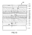
- Fig. 13 shows an example of a transflective liquid crystal display device using the transflective layer.
- the liquid crystal display device 100 has liquid crystal 103 held between a pair of transparent substrates 101 and 102.
- a reflecting layer 104 and an insulating layer 106 are deposited on the lower substrate 101.
- a lower electrode 108 is formed of a transparent conductive film, such as an indium tin oxide (hereinafter referred to as ITO) film, on the insulating layer 106, and the lower electrode 108 is covered with an alignment layer 107.
- ITO indium tin oxide
- a color filter 109 including R (red), G (green), and B (blue) pigmented films are formed on the upper substrate 102.
- a planarizing layer 111 is deposited on the color filter 109.
- Upper electrodes 112 are formed of a transparent conductive film, such as an ITO film, on the planarizing film 111, and the upper electrodes 112 are covered with an alignment layer 113.
- the reflecting layer 104 is formed of a metal having a high optical reflectivity, such as aluminium, and the reflecting layer 104 has a slit 110 for transmitting light in each pixel.
- the slits 110 allow the reflecting layer 104 to serve as a transflective layer (therefore, hereinafter, the reflecting layer 104 is referred to as a transflective layer).
- the upper substrate 102 is provided with a front diffuser 118, a retardation layer 119, and an upper polarizer 114 on the outer surface thereof, in that order from the upper substrate 102 side.
- the lower substrate 101 is provided with a quarter wave plate 115 and a lower polarizer 116 on the outer surface thereof, in that order.
- a backlight 117 (illumination device) is disposed under the lower surface of the lower substrate 101, that is, under the lower polarizer 116.
- liquid crystal display device 100 shown in Fig. 13 When the liquid crystal display device 100 shown in Fig. 13 is used in a reflective mode in a bright place, outside light entering through the upper substrate 102 from above, such as sunlight or illumination light, passes through the liquid crystal 103 to be reflected at the surface of the transflective layer 104 on the lower substrate 101, and then passes through the liquid crystal 103 again to be emitted to the upper substrate 102 side.
- light emitted from the backlight 117 under the lower substrate 101 passes through the slits 110 of the reflecting layer 104, and then passes through the liquid crystal 103 to be emitted to the upper substrate 102 side. This light contributes to displaying images in the respective modes.
- a metallic film having a high optical reflectivity such as an aluminium or silver film
- a dielectric mirror formed by alternately laminating dielectric thin layers having different refractive indexes a cholesteric reflector using a cholesteric liquid crystal, a hologram reflector using a hologram element, and the like have recently been proposed.
- These new types of reflectors not only serve as reflectors for reflecting light, making use of the characteristics of the constituents thereof, but also have a particular function.
- the cholesteric liquid crystal exhibits a liquid crystal phase at a specific temperature (liquid crystal transition temperature) or more, in which liquid crystal molecules are arranged in a regular helical manner with a constant pitch.
- This structure allows the cholesteric liquid crystal to selectively reflect only light having a wavelength corresponding to the pitch of the helix and, thus, to transmit the other light. Since the pitch of the helix can be controlled by, for example, changing the ultraviolet light intensity or the temperature when the liquid crystal is hardened, the color of reflected light is locally changeable and the cholesteric liquid crystal can, therefore, be used as a reflective color filter. Also, by laminating a plurality of cholesteric liquid crystal layers for selectively reflecting light of different colors, the resulting laminate can serve as a reflector for reflecting white light.
- the known transflective liquid crystal display device as shown in Fig. 13 has a problem in that, while displayed images can be viewed, regardless of the presence or absence of outside light, the brightness of images in a transmissive mode is much degraded in comparison with in a reflective mode. This is because, in the transmissive mode, no more than substantially half of light emitted from the backlight is used for displaying images and only the light passing through the slits of the transflective layer contributes to displaying images. This problem is also caused by the quarter wave plate and the lower polarizer disposed under the outer surface of the lower substrate and other reasons.
- the known transflective liquid crystal display device has two display modes which are used separately according to whether light is reflected or transmitted.
- substantially half of light emitted from the backlight is absorbed by the upper polarizer and, thus, only the rest half light is used for displaying images.
- a reflective mode almost all the linearly polarized light entering from the upper substrate side is used for displaying bright images.
- a transmissive mode the light traveling from the lower surface of the liquid crystal layer toward the upper substrate side must be circularly polarized in order to display images as in the reflective mode.
- half of the circularly polarized light is adsorbed by the upper polarizer while being emitted from the upper substrate to the outside. As a result, no more than substantially half of the light entering the liquid crystal layer can contribute to displaying images.
- the display principle of this liquid crystal display device itself originally has a factor responsible for making displayed images dark in a transmissive mode.
- the brightness of displayed images depends on the ratio of the entire slit area to the entire transflective layer area (that is, the aperture ratio). Although a larger aperture ratio improves the brightness in a transmissive mode, it reduces the area of the transflective layer other than the apertures. Consequently, displayed images become dark in a reflective mode.
- the aperture ratio of the slits cannot be increased beyond a certain level, in view of ensuring bright images in the reflective mode and, hence, it is limited to improve the brightness in the transmissive mode.
- the display principle of the transflective liquid crystal display device since a quarter wave plate is needed under the outer surface of the lower substrate, the brightness becomes insufficient in a transmissive mode. The reason will now be described.
- the following description refers to the structure in which dark images are displayed when a non-selection voltage is applied and bright images are displayed when a selection voltage is applied.
- the light is reflected at the surface of the transflective layer 104 on the lower substrate 101 to reverse the circular polarization direction thereof, and then passes through the liquid crystal 103 again to change to linearly polarized light having a polarization axis perpendicular to the drawing.
- the light reaches the upper substrate 102. Since the upper polarizer 114 disposed above the upper substrate 102 has a polarization axis parallel to the drawing, light reflected at the transflective layer 104 is absorbed by the upper polarizer 114 and it does not return to the outside (viewer side) of the liquid crystal display device 100.
- the liquid crystal display device 100 displays dark images.
- a voltage applied to the liquid crystal 103 changes the orientation direction of the liquid crystal 103.
- light entering from the outside of the upper substrate 102 changes to linearly polarized light and is subsequently reflected at the transflective layer 104.
- the linearly polarized light returns to the outside (viewer side) through the upper polarizer 114 disposed above the upper substrate 102 while maintaining the polarization axis parallel to the drawing.
- the liquid crystal display device 100 displays bright images.
- liquid crystal display device 100 displays images in a transmissive mode
- light emitted from the backlight 117 enters from the outside of the lower substrate 101 to the liquid crystal 103, and part of the light is transmitted through the slits 110 to contribute to displaying images.
- the light traveling to the upper substrate 102 through the slits 110 must be circularly polarized as in a reflective mode, as described above.
- the quarter wave plate 115 is required for converting the light linearly polarized by passing through the lower polarizer 116 to circularly polarized light.
- the light emitted from the backlight 117 changes to linearly polarized light perpendicular to the drawing on passing through the lower polarizer 116. Then, it passes through the quarter wave plate 115 to change to substantially circularly polarized light and reaches the transflective layer 104. The light is reflected at the lower surface of the transflective layer 104 to reverse the circular polarization direction, and passes through the quarter wave plate 115 again to change to linearly polarized light having a polarization axis parallel to the drawing.
- the linearly polarized light is absorbed by the lower polarizer 116 having a polarization axis perpendicular to the drawing.
- the light emitted from the backlight 117 and not transmitted through the slits 110 is reflected at the lower surface of the transflective layer 104, and is then almost completely absorbed by the lower polarizer 116 under the lower substrate 101.
- the transflective liquid crystal display device 100 As described above, almost all the light reflected at the transflective layer 104 without passing through the slits 110 in a transmissive mode is absorbed by the lower polarizer 116 under the lower substrate 101, and, therefore, only part of the light emitted from the backlight 117 can be used to display images. If the light can be transmitted through the lower polarizer 116 to return to the backlight 117 without being absorbed by the lower polarizer 116, the returned light is combined with light originally emitted from the backlight 117, thus improving the brightness of the backlight 117 effectively. Consequently, the brightness in a transmissive mode can be improved. In other words, if the light reflected at the transflective layer 104 without passing through the slits 110 can be reused to display images, the brightness in the transmissive mode can be improved. However, this has not been achieved in the known structure.
- the present invention is proposed to solve the problem described above, and one object of the present invention is to provide a transflective liquid crystal display device in which the brightness in a transmissive mode is improved to have excellent visibility. Another object of the present invention is to provide an electronic apparatus having the liquid crystal display device having the excellent visibility.
- a liquid crystal display device of the present invention includes a liquid crystal cell having an upper substrate, a lower substrate opposing the upper substrate, and a liquid crystal layer held between the upper substrate and the lower substrate.
- a color filter layer including a plurality of pigmented films containing different color pigments and a transflective layer including cholesteric liquid crystal films for reflecting part of elliptically polarized light in a predetermined direction and transmitting part of the elliptically polarized light are disposed on the inner surface of the lower substrate, in that order.
- An upper elliptically polarized light transmitting means for allowing elliptically polarized light to enter the liquid crystal layer from above the upper substrate and a lower elliptically polarized light transmitting means for allowing elliptically polarized light to enter the liquid crystal layer from below the lower substrate are provided.
- the liquid crystal layer reverses the polarized direction of the elliptically polarized light either when a selection voltage is applied or when a non-selection voltage is applied, and does not change the polarization when the other voltage is applied.
- At least part of the transmission spectrum of each pigmented film included in the color filter layer overlaps with the refection spectrum of the corresponding cholesteric liquid crystal film.
- Cholesteric liquid crystal has a so-called selective reflectivity which allows liquid crystal to reflect light circularly polarized in the same direction as the winding direction of the helical liquid crystal molecules and having a wavelength equivalent to the pitch of the helix. Conversely, the cholesteric liquid crystal transmits light having wavelengths different from the pitch of the helical molecules therein and light circularly polarized in the direction opposite to the winding direction of the helical molecules therein even if the light has a wavelength equivalent to the pitch of the helix.
- the cholesteric liquid crystal films of the present invention do not completely transmit, but partly reflects and partly transmits, light circularly polarized in the same direction as the winding direction of the helical molecules therein and having a wavelength equivalent to the pitch of the helix. This is one of the characteristic features of the present invention. This function allows the cholesteric liquid crystal films to serve as a transflective layer.
- the inventors found that, in a reflective liquid crystal display device using a reflecting layer formed of cholesteric liquid crystal, which has recently been proposed, light can be reflected and transmitted in the same display mode by setting the liquid crystal to a mode in which light entering a liquid crystal cell is elliptically polarized and in which the polarized direction of the elliptically polarized light is reversed either when a selection voltage is applied or when a non-selection voltage is applied, and that, thus, images displayed in a transmissive mode do not become dark, according to the display principle.
- the inventors also found that light reflected toward the lower substrate by the selective reflectivity of the cholesteric liquid crystal in a transmissive display mode is reusable even if the structure of the outer surface side of the lower substrate is the same as the conventional structure. Focusing attention on these points, the inventors have reached the present invention.
- the display principle of the liquid crystal display device of the present invention and the reason why light reflected at the transflective layer is reusable will now be described with reference to Fig. 3.
- Fig. 3 is a schematic illustration of the display principle of the liquid crystal display device according to the present invention.
- the lower substrate 2 is provided with a color filter layer 6 (hereinafter referred to as a pigmented color filter layer, occasionally) including pigmented films 5 (illustrated as red (R) pigmented films in Fig. 3) and a transflective layer 7 including cholesteric liquid crystal films 8, in that order, on the inner surface thereof.
- the cholesteric liquid crystal films 8 reflect part of light circularly polarized in a predetermined direction and having a predetermined wavelength band (color) and transmit part of the same.
- the cholesteric liquid crystal films 8 reflect 80% of a red light circularly polarized clockwise (hereinafter referred to as a right-handed circularly polarized light) and transmit 20% of the red light.
- the transmission spectrum of the pigmented films 5 of the color filter layer 6 overlaps with the reflection spectrum of the cholesteric liquid crystal films 8 overlying the pigmented films 5.
- the cholesteric liquid crystal films 8 for selectively reflecting red light are disposed above the pigmented films 5 for transmitting the red light.
- the liquid crystal display device of the present invention has an upper elliptically polarized light transmitting means for allowing the elliptically polarized light to enter the liquid crystal layer 3 from the upper substrate 1 side.
- the upper elliptically polarized light transmitting means includes an upper polarizer 9 for transmitting light linearly polarized in one direction and an upper quarter wave plate 10 for converting the linearly polarized light transmitted through the upper polarizer 9 to circularly polarized light.
- a lower elliptically polarized light transmitting means is also provided for allowing the elliptically polarized light to enter the liquid crystal layer 3 from the lower substrate 2 side.
- the lower elliptically polarized light transmitting means includes a lower polarizer 11 and a lower quarter wave plate 12, as in the upper substrate 1 side. At the upper substrate side and the lower substrate side, both polarization axes of the polarizers 9 and 11 extend in parallel with the drawing Fig. 3. When light linearly polarized in this direction enters the quarter wave plates 10 and 12, right-handed circularly polarized light is emitted.
- the liquid crystal layer 3 is intended to reverse the polarization (rotation direction) of circularly polarized light entering the liquid crystal layer 3 according to whether a selection voltage is applied.
- a non-selection voltage when liquid crystal is in an off state, the liquid crystal layer 3 has a phase difference of ⁇ /2 ( ⁇ is the wavelength of incident light) with the liquid crystal molecules 13 lying. Therefore, right-handed circularly polarized light entering the liquid crystal layer 3 is transmitted to change to left-handed circularly polarized light and, in contrast, left-handed circularly polarized light changes to right-handed circularly polarized light.
- a selection voltage when a selection voltage is applied (when the liquid crystal is in an on state) so that the liquid crystal molecules 13 rise, the phase difference disappears and, therefore, the polarization (rotation direction) of the circularly polarized light does not change.
- a big difference between the known transflective layer using a metallic film and the transflective layer of the present invention using the cholesteric liquid crystal is that while the metallic transflective layer reverses the rotation direction of circularly polarized light when the light is reflected, the cholesteric liquid crystal transflective layer does not reverse the rotation direction of the circularly polarized light when the light is reflected. Specifically, while right-handed circularly polarized light reflected at the metallic transflective layer changes to left-handed circularly polarized light, right-handed circularly polarized light reflected at the cholesteric liquid crystal transflective layer remains right-handed.
- the right-handed circularly polarized red light is reflected at the transflective layer 7 above the lower substrate 2 and is transmitted through the liquid crystal layer 3 again toward the upper substrate 1. Since the liquid crystal is in an on state at this time, the right-handed circularly polarized light remains right-handed. However, the light subsequently passes through the upper quarter wave plate 10 to change to linearly polarized light having a polarization axis parallel to the drawing and which is capable of passing through the upper polarizer 9. Thus, the light returns to the outside (viewer side) so that the liquid crystal display device displays bright (red) images.
- the liquid crystal display device displays images in a transmissive mode
- light emitted from, for example, a backlight enters the liquid crystal cell 4 from the outside of the lower substrate 2 to contribute to displaying images.
- substantially the same action as in the reflective mode occurs from the lower substrate 2 side to the upper substrate 1 side.
- the lower substrate 2 since the lower substrate 2 has the lower polarizer 11 and the lower quarter wave plate 12 as in the upper substrate 1, right-handed circularly polarized light enters the liquid crystal layer 3 from the lower substrate 2 side, and 20% of the light passes through the transflective layer 7.
- the liquid crystal display device displays dark images.
- the right-handed circularly polarized light subsequently passes through the upper quarter wave plate 10 to change to linearly polarized light having a polarization axis parallel to the drawing and which is capable of passing through the upper polarizer 9, the light returns to the outside (viewer side) so that the liquid crystal display device displays bright (red) images.
- the linearly polarized light having the same polarization axis as that of the lower polarizer 11 is emitted from the lower substrate 2 side. Then, the light is reflected at, for example, a reflector provided at the backlight, and enters the liquid crystal cell 4 again to be reused for displaying images.
- the liquid crystal display device of the present invention can reflect and transmit light in the same display mode.
- a large amount of light transmitted through the transflective layer including the cholesteric liquid crystal contributes to displaying images without the upper polarizer absorbing part of the light entering from the lower substrate side.
- light reflected at the transflective layer including the cholesteric liquid crystal is reused for displaying images.
- the ratio of the reflection to the transmission that is, a reflection ratio of 80% and a transmission ratio of 20%, of the cholesteric liquid crystal is, of course, by way of an example, and the ratio of the reflection to the transmission may be varied.
- the above-described light entering from the upper substrate side and lower substrate side is illustrated as an ideal example, or "(right-handed) circularly polarized light". However, it is not necessarily circularly polarized in order to realize the above-described function of the liquid crystal display device of the present invention, as long as it is "elliptically polarized light" in a broad sense.
- the liquid crystal display device of the present invention may further have an illumination device for emitting light to the liquid crystal cell from below the lower substrate.
- elliptically polarized light must be emitted from below the lower substrate by some means. Any possible means can be taken for that purpose, and, by providing an illumination device for emitting light to the liquid crystal cell from the lower substrate side, that is, a so-called backlight, a structure allowing elliptically polarized light to enter from the lower substrate side can be readily achieved.
- the upper elliptically polarized light transmitting means and the lower elliptically polarized light transmitting means may each include a polarizer for transmitting light linearly polarized in one direction and a retardation layer for changing the linearly polarized light transmitted through the polarizer to elliptically polarized light.
- the retardation layer can have any phase difference, but, preferably, it is a quarter wave plate.
- the quarter wave plate changes linearly polarized light emitted from the polarizer into elliptically polarized light, and particularly into circularly polarized light, the light use efficiency increases most and, thus, the liquid crystal display device can display brighter images. If the upper retardation layer disposed above the upper substrate needs a color compensation function, however, the quarter wave plate is not necessarily used as the retardation layer, and any retardation film having a desired phase difference can be used.
- the cholesteric liquid crystal films may each serve as a reflective color filter, in a predetermined region, for selectively reflecting colored light having a wavelength corresponding to the pitch of helical liquid crystal molecules therein, and at least part of the reflection spectrum of each cholesteric liquid crystal film overlaps with the transmission spectrum of the corresponding pigmented film included in the color filter layer.
- the color of light reflected at the cholesteric liquid crystal films and the color of light transmitted through the pigmented films of the color filter layer are the same.
- the cholesteric liquid crystal films for the liquid crystal display device of the present invention may be multilayer films in which a plurality of cholesteric liquid crystal films including helical liquid crystal molecules having different pitches are laminated.
- the cholesteric liquid crystal films can serve as so-called white reflectors, which reflect circularly polarized light having various wavelengths.
- the cholesteric liquid crystal films can each serve as a reflective color filter for reflecting, for example, red (R), green (G), or blue (B) light.
- R red
- G green
- B blue
- the liquid crystal display device may further include, at the predetermined regions between the lower substrate and the color filter layer, additional cholesteric liquid crystal films for reflecting at least part of colored light having wavelengths outside the reflection spectrum of the respective cholesteric liquid crystal films of the transflective layer.
- the liquid crystal display device may further include, in predetermined regions between the lower substrate and the color filter layer, additional cholesteric liquid crystal films for reflecting at least part of light having a color complementary to the color of light transmitted through the respective pigmented films of the color filter layer.
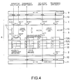
- Fig. 4 is different from Fig. 3 in that additional cholesteric liquid crystal films for selectively reflecting colored light having wavelengths outside the reflection spectrum of the cholesteric liquid crystal films included in the transflective layer are disposed under the pigmented color filter layer formed above the lower substrate. Specifically, the additional cholesteric liquid crystal films selectively reflect light having a color complementary to the color of light transmitted through the pigmented films of the color filter layer.
- the color of light reflected at the cholesteric liquid crystal films included in the transflective layer and the color of light transmitted through the pigmented color filter layer are red (R), and additional two-layered cholesteric liquid crystal films for selectively reflecting green (G) and blue (B) lights are deposited.
- R red
- additional two-layered cholesteric liquid crystal films for selectively reflecting green (G) and blue (B) lights are deposited.
- a reflective mode circularly polarized red light from the upper substrate 1 side toward the lower substrate 2 is transmitted through the pigmented films 5 of the pigmented color filter layer 6 and passes through cholesteric liquid crystal films 14 for selectively reflecting green light and cholesteric liquid crystal films 15 for selectively reflecting blue light. Also, green light and blue light are selectively reflected at the respective lower cholesteric liquid crystal films 14 and 15 to travel toward the upper substrate 1 side again. However, this light is absorbed by the red pigmented films 5 of the pigmented color filter layer 6 and is not emitted to the liquid crystal layer 3. In the reflective mode, therefore, the display principle is substantially the same as in the description above.
- the green and blue light components of the light are reflected without being absorbed by the red pigmented films 5, thus being reused as well as red light components reflected at the transflective layer 7.
- the reuse efficiency increases and, thus, brighter transmissive display images can be displayed.
- An electronic apparatus of the present invention comprises a liquid crystal display device of the present invention described above.
- an electronic apparatus which includes a liquid crystal display device having excellent visibility and capable of displaying bright images even in a transmissive mode.
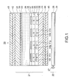
- Fig. 1 is a sectional view of a liquid crystal display device according to the first embodiment and shows an exemplary transflective liquid crystal color display device.
- a liquid crystal display device according to the first embodiment and shows an exemplary transflective liquid crystal color display device.
- thicknesses, dimensional ratios, and the like of the components are changed if necessary.
- a liquid crystal display device 20 has a liquid crystal cell 21 and a backlight 22 (illumination device), as shown in Fig. 1.
- the liquid crystal cell 21 has a lower substrate 23 and an upper substrate 24 opposing each other and a liquid crystal layer 26 held between the lower substrate 23 and the upper substrate 24.
- the liquid crystal layer 26 is formed of, for example, STN (super twisted nematic) liquid crystal whose phase difference is set at ⁇ /2.
- the backlight 22 is disposed at the backside (the outer surface side of the lower substrate 23) of the liquid crystal cell 21.
- the backlight 22 includes a light source 27 such as a LED (light-emitting diode), a light guide plate 28, and a reflector 29, and the like.
- a pigmented color filter layer 32 including pigmented films 31r, 31g, and 31b containing, for example, respective color pigments R, G, and B is formed on the inner surface of the lower substrate 23 formed of a light-transmitting material, such as glass or plastics.
- a transflective layer 35 including cholesteric liquid crystal films 34r, 34g, and 34b for selectively reflecting light of the respective colors R, G, and B is formed above the pigmented color filter layer 32 with an overcoat layer 33 therebetween.
- Each of the cholesteric liquid crystal films 34r, 34g, and 34b reflects part of the corresponding colored light circularly polarized in a predetermined direction.
- the ratio of the reflection to the transmission is set in the range of 8:2 to 1:9.
- the ratio may be set by controlling the thickness of the cholesteric liquid crystal films 34r, 34g, and 34b.
- the transmission spectrums of the pigmented films 31r, 31g, and 31b of the pigmented color filter layer 32 substantially overlap with the reflection spectrums of the respective cholesteric liquid crystal films 34r, 34g, and 34b overlying the pigmented color filter layer 32.
- the cholesteric liquid crystal film 34r for selectively reflecting red light overlies the pigmented film 31r for transmitting red light
- the cholesteric liquid crystal film 34g for selectively reflecting green light overlies the pigmented film 31g for transmitting green light
- the cholesteric liquid crystal film 34b for selectively reflecting blue light overlies the pigmented film 31b for transmitting blue light.
- the cholesteric liquid crystal films 34r, 34g, and 34b are each intended to selectively reflect light having a wavelength corresponding to the pitch of the helical liquid crystal molecules thereof.
- the helical pitch can be locally controlled by, for example, changing the intensity of ultraviolet light or the temperature when the cholesteric liquid crystal is hardened.
- a cholesteric liquid crystal film having a helical pitch set at about 450 nm selectively reflects blue light; a cholesteric liquid crystal film having a helical pitch set at about 550 nm selectively reflects green light; and a cholesteric liquid crystal film having a helical pitch set at about 650 nm selectively reflects red light.
- all the cholesteric liquid crystal films serve as reflective color filters.
- the pigmented color filter layer 32 mainly serves as color filters to produce colors of transmissive display images.
- the pigmented films 31r, 31g, and 31b of these pigmented color filter layer 32 and the cholesteric liquid crystal films 34r, 34g, and 34b overlying the pigmented films may be patterned in plan view as in conventional color filter patterns, such as a stripe pattern, a mosaic pattern, and a delta pattern.
- Lower electrodes 37 are formed of a transparent conductive film, such as ITO, on the overcoat layer 36 formed on the transflective layer 35, at the inner surface side of the lower substrate 23.
- An alignment layer 38 is formed of a resin such as polyimide on the lower electrodes 37.
- an upper electrode 39 is formed of a transparent conductive film, such as ITO, and an alignment layer 40 is formed of a resin, such as polyimide, on the upper electrode 39.
- the lower electrodes 37 and the upper electrode 39 may be structured by an active matrix system using switching elements, such as thin film transistors (TFTs) and thin film diodes (TFDs), or by a passive matrix system.
- TFTs thin film transistors
- TFDs thin film diodes
- An upper retardation layer 42 and an upper polarizer 43 are formed at the outer surface side of the upper substrate 24, in that order from the substrate side.
- a lower retardation layer 44 and a lower polarizer 45 are formed at the outer surface side of the lower substrate 23, in that order from the substrate side.
- the upper and lower retardation layers 42 and 44 and polarizers 43 and 45 are intended to allow light circularly polarized in a predetermined direction to enter the liquid crystal layer 26.
- the rotation directions of circularly polarized light entering from the upper substrate 24 side and circularly polarized light entering from the lower substrate 23 side must be substantially the same.
- the directions of the polarization axes of the upper polarizer 43 and the lower polarizer 45 must be substantially the same, as in Fig. 1, where both the directions are parallel to the drawing.
- a quarter wave plate is not necessarily used as the retardation layer, and any retardation film having a desired phase difference can be used.
- the liquid crystal display device 20 of the present embodiment can reflect and transmit light in the same display mode.
- the transflective layer 35 including the cholesteric liquid crystal films 34r, 34g, and 34b contributes to displaying images without the upper polarizer absorbing part of the light entering from below the lower substrate 23, not as in the known transflective liquid crystal display device.
- Light reflected at the transflective layer 35 including the cholesteric liquid crystal films 34r, 34g, and 34b and thus not entering the liquid crystal layer 26 can be reused for transmissive display images.
- the effect of fully using circularly polarized light transmitted through the transflective layer 35 including the cholesteric liquid crystal films 34r, 34g, and 34b and the effect of reusing circularly polarized light reflected at the transflective layer 35 for displaying images improve the brightness of transmissive display images while maintaining the brightness of reflective display images.
- the transflective liquid crystal display device having excellent visibility can be achieved.
- Fig. 2 is a sectional view of a liquid crystal display device according to the second embodiment.
- the fundamental structure of a liquid crystal display device of the present embodiment is the same as in the first embodiment except that additional cholesteric liquid films are further provided under the pigmented color filter layer.
- Fig. 2 the same parts as in Fig. 1 are designated by the same reference numerals and the description is not repeated.
- a liquid crystal display device 50 of the second embodiment has a cholesteric liquid crystal layer 51 for selectively reflecting colored light having wavelengths outside the reflection spectrum of the cholesteric liquid crystal films 34r, 34g, and 34b included in the transflective layer 35, between the lower substrate 23 and the pigmented color filter layer 32.
- the cholesteric liquid crystal layer 51 selectively reflects light having colors complementary to the colors of light transmitted through the pigmented films 31r, 31g, and 31b of the pigmented color filter layer 32.
- the region (34r and 31r) where the color of light reflected at the cholesteric liquid crystal films of the transflective layer 35 and the color of light transmitted through the pigmented color filter layer 32 are red (R) has two-layered cholesteric liquid crystal films 52g and 52b for selectively reflecting green (G) light and blue (B) light, respectively;
- the region (34b and 31b) where the color of light reflected at the cholesteric liquid crystal films of the transflective layer 35 and the color of light transmitted through the pigmented color filter layer 32 are blue (B) has two-layered cholesteric liquid crystal films 52r and 52g for selectively reflecting red (
- the cholesteric liquid crystal layer 51 may be formed of single-layered cholesteric liquid crystal films, instead of the two-layered cholesteric liquid crystal films.
- single-layered cholesteric liquid crystal films for selectively reflecting cyanic light, magenta light, and yellow light are disposed at the regions transmitting red (R) light, green (G) light, and blue (B) light, respectively.
- the cholesteric liquid crystal layer 51 may be composed of three or more layers including cholesteric liquid crystal films which selectively reflect light of complementary colors.
- the display principle of the liquid crystal display device 50 according to the present embodiment has also been described above and is not repeated.
- circularly polarized light emitted from the lower retardation layer 44 in the transmissieve display mode enters the cholesteric liquid crystal layer 51 before entering pigmented films 31r, 31g, and 31b of the pigmented color filter layer 32. Therefore components of circularly polarized colored light complementary to the colors of the pigmented films 31r, 31g, and 31b of the pigmented color filter layer 32 are reflected at the cholesteric liquid crystal films 52r, 52g, and 52b without being absorbed by the pigmented films 31r, 31g, and 31b, thus being reused. As a result, light reuse efficiency increases as a whole and, thus, brighter transmissive display images can be displayed.
- Fig. 5 shows the reflection spectrum around 550 nm of cholesteric liquid crystal films and the transmission spectrum around 550 nm of a pigmented color filter, according to the third embodiment. Specifically, a region corresponding to a green (G) pigmented film of the pigmented color filter is shown. Although only the green (G) region is described here, red (R) and blue (B) regions are the same. Light having transmission wavelengths emitted from a backlight is transmitted through the regions not having the reflection spectrum.
- the fundamental structure of a liquid crystal display device of the present embodiment is the same as in the first embodiment except that the reflection spectrum of the cholesteric liquid crystal films disposed above the pigmented color filter layer is narrower than the transmission spectrum of the pigmented color filter layer.
- a reflection spectrum narrower than a transmission spectrum means that the band width between wavelengths corresponding to half the transmittance (referred to as the half band width of the transmission spectrum) includes the half band width of the reflection spectrum.
- the half band width of the transmission spectrum is in the range of 500 to 580 nm and that the half band width of the reflection spectrum is in the range of 520 to 560 nm and, hence, represents the third embodiment.
- the structure of the third embodiment is the same as in Fig. 1 and the description is not repeated.
- band width of a selective reflection spectrum is proportional to the refractive index anisotropy ⁇ n of a cholesteric liquid crystal film, a smaller band width of the reflection spectrum is realized by setting the refractive index anisotropy ⁇ n small.
- the transmittance can be increased.
- Fig. 6 is a sectional view of a liquid crystal display device according to the present embodiment.
- the fundamental structure of a liquid crystal display device of the present embodiment is the same as in the first embodiment except that the area of the cholesteric liquid crystal layer disposed above the pigmented color filter layer is set smaller than that of the pigmented color filter layer, and the cholesteric liquid crystal layer and the pigmented color filter layer are separated by a light-transmitting layer.
- the same parts as in Fig. 1 are designated by the same reference numerals and the description is not repeated.
- the regions not having the cholesteric liquid crystal layer thereabove are present, and the pigmented color filter layer is covered with the light-transmitting layer. Light emitted from the backlight can pass through these regions to enter the liquid crystal layer without being reflected at the cholesteric liquid crystal films. Thus, the transmittance can be increased.
- Fig. 7 shows the reflection spectrum around 550 nm of cholesteric liquid crystal films and the transmission spectrum around 550 nm of a pigmented color filter, according to the fifth embodiment.
- the fundamental structure of a liquid crystal display device of the present embodiment is the same as in the first embodiment except that the cholesteric liquid crystal films are formed so as to reflect and transmit light having specific wavelengths.
- the structure of the present embodiment is the same as in Fig. 1 and the description is not repeated.
- the cholesteric liquid crystal films of the present embodiment are formed so as to reflect and transmit light having specific wavelengths.
- the cholesteric liquid crystal films are formed so as to have a thickness smaller than that of cholesteric liquid crystal films for reflecting the entire light having specific wavelengths. In this structure, the amount of illumination light from the backlight transmitted through the cholesteric liquid crystal films can be increased and, thus, bright images can be expected.
- Fig. 8 shows the reflection spectrum around 550 nm of cholesteric liquid crystal films and the transmission spectrum around 550 nm of a pigmented color filter, according to the sixth embodiment.
- the fundamental structure of a liquid crystal display device of the present embodiment is the same as in the second embodiment except that the reflection spectrum of the cholesteric liquid crystal layer disposed between the lower substrate and the pigmented color filter layer is narrower than the spectrum complementary to the transmission spectrum of the pigmented films of the pigmented color filter layer.
- the structure of the present embodiment is the same as in Fig. 2 and the description is not repeated.
- the reflection spectrum of the cholesteric liquid crystal layer disposed between the lower substrate and the pigmented color filter layer is narrower than the spectrum complementary to the transmission spectrum of the pigmented films of the pigmented color filter layer, and thus the light can be reused.
- color mixture is prevented in reflective display images. As a result, light reuse efficiency increases as a whole and, thus, brighter transmissive display images can be displayed.
- green (G) wavelength band is described here, red (R) and blue (B) wavelength bands are also the same.
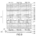
- Fig. 9 is a sectional view of a liquid crystal display device according to the seventh embodiment.
- the fundamental structure of a liquid crystal display device according to the present embodiment is the same as in the second embodiment except that the area of the cholesteric liquid crystal films disposed between the lower substrate and the pigmented color filter layer is larger than the area of the pigmented films of the pigmented color filter layer.
- the same parts as in Fig. 2 are designated by the same reference numerals and the description is not repeated.
- the area of the cholesteric liquid crystal films disposed between the lower substrate and the pigmented color filter layer is larger than the area of the pigmented films of the pigmented color filter layer, and thus the light can be reused.
- light reuse efficiency increases as a whole and, thus, brighter transmissive display images can be displayed.
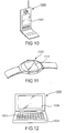
- Fig. 10 is a perspective view of an exemplary cellular telephone.
- numeral 1000 designates the main body of a cellular phone and numeral 1001 designates a liquid crystal display using the liquid crystal display device described above.
- Fig. 11 is a perspective view of an exemplary wristwatch-type electronic apparatus.
- numeral 1100 designates the main body of a wristwatch and numeral 1101 designates a liquid crystal display using the liquid crystal display device described above.
- Fig. 12 is a perspective view of an exemplary portable information processing apparatus, such as a word processor or a personal computer.
- numeral 1200 designates an information processing apparatus
- numeral 1202 designates an input portion such as a keyboard
- numeral 1204 designates the main body of the information processing apparatus
- numeral 1206 designates a liquid crystal display using the liquid crystal display device described above.
- these electronic apparatuses shown in Figs. 10 to 12 each have a liquid crystal display using any one of the liquid crystal display devices according to the above-described embodiments, bright images can be displayed even in a transmissive mode. Hence, the electronic apparatuses each have a liquid crystal display ensuring excellent visibility in every place.
- the technical scope of the present invention is not limited to the above-described embodiments, and various modifications may be made without departing from the scope of the invention.
- the quarter wave plate is used as a elliptically polarized light-transmitting means in the embodiments, any optical material may be used as long as it is capable of allowing elliptically polarized light to enter the liquid crystal layer.
- circularly polarized light enter the liquid crystal layer.
- incident light is not necessarily limited to perfect circularly polarized light, and if the decrease of light use efficiency is acceptable in some degree, elliptically polarized light may be used.
- the color of light transmitted through the pigmented films of the pigmented color filter layer and the color of light reflected at the respective cholesteric liquid crystal films are the same, that is, the transmission spectrum of the pigmented films of the pigmented color filter layer substantially overlaps with the reflection spectrum of the respective cholesteric liquid crystal films.
- these two spectrums may at least partly overlap.
- the liquid crystal display device of the present invention can reflect and transmit light in the same display mode. Particularly in a transmissive mode, most of the light transmitted through the transflective layer including cholesteric liquid crystal contributes to displaying images without the upper polarizer absorbing part of the light entering from the lower substrate side, as in a known transflective liquid crystal display device. Also, light reflected at the transflective layer including the cholesteric liquid crystal and thus not entering the liquid crystal layer is reused for displaying images. Thus, a transflective liquid crystal display device can be achieved which increases the brightness of transmissive display images while maintaining the brightness of reflective display images and thus has excellent visibility.
Landscapes
- Physics & Mathematics (AREA)
- Nonlinear Science (AREA)
- Mathematical Physics (AREA)
- Chemical & Material Sciences (AREA)
- Crystallography & Structural Chemistry (AREA)
- General Physics & Mathematics (AREA)
- Optics & Photonics (AREA)
- Liquid Crystal (AREA)
- Polarising Elements (AREA)
- Optical Filters (AREA)
Abstract
A liquid crystal display device 20 of the present invention has an upper substrate 24 and a lower substrate 23 opposing each other and liquid crystal 26 held between the upper substrate 24 and the lower substrate 23. A transflective layer 35 including cholesteric liquid crystal films 34r, 34g, and 34b are disposed above the lower substrate 23. A backlight 22 is also provided. Retardation layers 42 and 44 and polarizers 43 and 45 are disposed outside the upper substrate 24 and the lower substrate 23, respectively, in that order from the substrate sides. A pigmented color filter layer 32 including pigmented films 31r, 31g, and 31b underlies the transflective layer 35 to transmit light of the same color as that of light selectively reflected at the respective cholesteric liquid crystal films 34r, 34g, and 34b.
Description
- The present invention relates to liquid crystal display devices and to electronic apparatuses. In particular, it relates to a structure of transflective liquid crystal display devices having excellent visibility and which can display sufficiently bright images not only in a reflective display mode but also in a transmissive display mode.
- Reflective liquid crystal display devices reduce power consumption because they do not have any light sources, such as a backlight. Therefore they have been used for various portable electronic apparatuses or the like. However, since the reflective liquid crystal display devices use outside light, such as natural light or illumination light to display images, it is difficult to view the images in dark places. Accordingly, another type of liquid crystal display device has been suggested which uses outside light in bright places, as in the conventional reflective liquid crystal display devices, and uses an internal light source to make displayed images visible in dark places. Hence, this type of liquid crystal display device uses a display system serving as both a reflective display and a transmissive display. In this system, a reflective display mode or a transmissive display mode is selected according to the ambient brightness, thereby displaying clear images even in dark places while reducing the power consumption. Hereinafter, this type of liquid crystal display device is referred to as a "transflective liquid crystal display device", in this specification.
- A transflective liquid crystal display device has been proposed which has a reflecting layer having slits (apertures) for transmitting light and formed of a metal such as aluminium on the inner surface of a lower substrate (hereinafter, the liquid crystal side surfaces of substrates may be referred to as inner surfaces and the opposite surfaces may be referred to as outer surfaces) and which allows the reflecting layer to serve as a transflective layer. In this liquid crystal display device, by providing the metallic film on the inner surface of the lower substrate, the parallax effect due to the thickness of the lower substrate is reduced. In particular, color mixture is prevented in a structure having color filters.
- Fig. 13 shows an example of a transflective liquid crystal display device using the transflective layer.
- The liquid
crystal display device 100 hasliquid crystal 103 held between a pair oftransparent substrates layer 104 and aninsulating layer 106 are deposited on thelower substrate 101. Alower electrode 108 is formed of a transparent conductive film, such as an indium tin oxide (hereinafter referred to as ITO) film, on theinsulating layer 106, and thelower electrode 108 is covered with analignment layer 107. On the other hand, on theupper substrate 102, acolor filter 109 including R (red), G (green), and B (blue) pigmented films are formed. A planarizinglayer 111 is deposited on thecolor filter 109.Upper electrodes 112 are formed of a transparent conductive film, such as an ITO film, on theplanarizing film 111, and theupper electrodes 112 are covered with analignment layer 113. - The reflecting
layer 104 is formed of a metal having a high optical reflectivity, such as aluminium, and the reflectinglayer 104 has aslit 110 for transmitting light in each pixel. Theslits 110 allow the reflectinglayer 104 to serve as a transflective layer (therefore, hereinafter, the reflectinglayer 104 is referred to as a transflective layer). In addition, theupper substrate 102 is provided with afront diffuser 118, aretardation layer 119, and anupper polarizer 114 on the outer surface thereof, in that order from theupper substrate 102 side. Thelower substrate 101 is provided with aquarter wave plate 115 and alower polarizer 116 on the outer surface thereof, in that order. Also, a backlight 117 (illumination device) is disposed under the lower surface of thelower substrate 101, that is, under thelower polarizer 116. - When the liquid
crystal display device 100 shown in Fig. 13 is used in a reflective mode in a bright place, outside light entering through theupper substrate 102 from above, such as sunlight or illumination light, passes through theliquid crystal 103 to be reflected at the surface of thetransflective layer 104 on thelower substrate 101, and then passes through theliquid crystal 103 again to be emitted to theupper substrate 102 side. On the other hand, when the liquidcrystal display device 100 is used in a transmissive mode in a dark place, light emitted from thebacklight 117 under thelower substrate 101 passes through theslits 110 of the reflectinglayer 104, and then passes through theliquid crystal 103 to be emitted to theupper substrate 102 side. This light contributes to displaying images in the respective modes. - In such a transflective liquid crystal display device, a metallic film having a high optical reflectivity, such as an aluminium or silver film, has been used as the reflecting layer. On the other hand, a dielectric mirror formed by alternately laminating dielectric thin layers having different refractive indexes, a cholesteric reflector using a cholesteric liquid crystal, a hologram reflector using a hologram element, and the like have recently been proposed. These new types of reflectors not only serve as reflectors for reflecting light, making use of the characteristics of the constituents thereof, but also have a particular function.
- In particular, the cholesteric liquid crystal exhibits a liquid crystal phase at a specific temperature (liquid crystal transition temperature) or more, in which liquid crystal molecules are arranged in a regular helical manner with a constant pitch. This structure allows the cholesteric liquid crystal to selectively reflect only light having a wavelength corresponding to the pitch of the helix and, thus, to transmit the other light. Since the pitch of the helix can be controlled by, for example, changing the ultraviolet light intensity or the temperature when the liquid crystal is hardened, the color of reflected light is locally changeable and the cholesteric liquid crystal can, therefore, be used as a reflective color filter. Also, by laminating a plurality of cholesteric liquid crystal layers for selectively reflecting light of different colors, the resulting laminate can serve as a reflector for reflecting white light.
- However, the known transflective liquid crystal display device as shown in Fig. 13 has a problem in that, while displayed images can be viewed, regardless of the presence or absence of outside light, the brightness of images in a transmissive mode is much degraded in comparison with in a reflective mode. This is because, in the transmissive mode, no more than substantially half of light emitted from the backlight is used for displaying images and only the light passing through the slits of the transflective layer contributes to displaying images. This problem is also caused by the quarter wave plate and the lower polarizer disposed under the outer surface of the lower substrate and other reasons.
- The known transflective liquid crystal display device has two display modes which are used separately according to whether light is reflected or transmitted. In particular, when the light is transmitted, substantially half of light emitted from the backlight is absorbed by the upper polarizer and, thus, only the rest half light is used for displaying images. Specifically, in a reflective mode, almost all the linearly polarized light entering from the upper substrate side is used for displaying bright images. In contrast, in a transmissive mode, the light traveling from the lower surface of the liquid crystal layer toward the upper substrate side must be circularly polarized in order to display images as in the reflective mode. However, half of the circularly polarized light is adsorbed by the upper polarizer while being emitted from the upper substrate to the outside. As a result, no more than substantially half of the light entering the liquid crystal layer can contribute to displaying images. The display principle of this liquid crystal display device itself originally has a factor responsible for making displayed images dark in a transmissive mode.
- Also, since the light transmitted through the slits is used to display images in a transmissive mode, the brightness of displayed images depends on the ratio of the entire slit area to the entire transflective layer area (that is, the aperture ratio). Although a larger aperture ratio improves the brightness in a transmissive mode, it reduces the area of the transflective layer other than the apertures. Consequently, displayed images become dark in a reflective mode. The aperture ratio of the slits cannot be increased beyond a certain level, in view of ensuring bright images in the reflective mode and, hence, it is limited to improve the brightness in the transmissive mode.
- According to the display principle of the transflective liquid crystal display device, since a quarter wave plate is needed under the outer surface of the lower substrate, the brightness becomes insufficient in a transmissive mode. The reason will now be described. The following description refers to the structure in which dark images are displayed when a non-selection voltage is applied and bright images are displayed when a selection voltage is applied.
- First, when the liquid
crystal display device 100 displays dark images in a reflective mode will be described with reference to the liquid crystal display device shown in Fig. 13. Light entering from the outside of theupper substrate 102 passes through theupper polarizer 114 disposed above theupper substrate 102 to change to linearly polarized light having a polarization axis parallel to the drawing when the polarization axis of theupper polarizer 114 is parallel to the drawing. Then, while passing through theliquid crystal 103, the light changes to substantially circularly polarized light by birefringence of theliquid crystal 103. The light is reflected at the surface of thetransflective layer 104 on thelower substrate 101 to reverse the circular polarization direction thereof, and then passes through theliquid crystal 103 again to change to linearly polarized light having a polarization axis perpendicular to the drawing. Thus, the light reaches theupper substrate 102. Since theupper polarizer 114 disposed above theupper substrate 102 has a polarization axis parallel to the drawing, light reflected at thetransflective layer 104 is absorbed by theupper polarizer 114 and it does not return to the outside (viewer side) of the liquidcrystal display device 100. Thus, the liquidcrystal display device 100 displays dark images. - On the other hand, when bright images are displayed in a reflective mode, a voltage applied to the
liquid crystal 103 changes the orientation direction of theliquid crystal 103. As a result, after passing through theliquid crystal 103, light entering from the outside of theupper substrate 102 changes to linearly polarized light and is subsequently reflected at thetransflective layer 104. The linearly polarized light returns to the outside (viewer side) through theupper polarizer 114 disposed above theupper substrate 102 while maintaining the polarization axis parallel to the drawing. Thus, the liquidcrystal display device 100 displays bright images. - When the liquid
crystal display device 100 displays images in a transmissive mode, light emitted from thebacklight 117 enters from the outside of thelower substrate 101 to theliquid crystal 103, and part of the light is transmitted through theslits 110 to contribute to displaying images. - In this instance, in order that the liquid
crystal display device 100 displays dark images, the light traveling to theupper substrate 102 through theslits 110 must be circularly polarized as in a reflective mode, as described above. Hence, in order to substantially circularly polarize the light emitted from thebacklight 117 and transmitted through theslits 110, thequarter wave plate 115 is required for converting the light linearly polarized by passing through thelower polarizer 116 to circularly polarized light. - As for light not transmitted through the
slits 110 in the light emitted from thebacklight 117, when the polarization axis of thelower polarizer 116 is perpendicular to the drawing, the light emitted from thebacklight 117 changes to linearly polarized light perpendicular to the drawing on passing through thelower polarizer 116. Then, it passes through thequarter wave plate 115 to change to substantially circularly polarized light and reaches thetransflective layer 104. The light is reflected at the lower surface of thetransflective layer 104 to reverse the circular polarization direction, and passes through thequarter wave plate 115 again to change to linearly polarized light having a polarization axis parallel to the drawing. The linearly polarized light is absorbed by thelower polarizer 116 having a polarization axis perpendicular to the drawing. In other words, the light emitted from thebacklight 117 and not transmitted through theslits 110 is reflected at the lower surface of thetransflective layer 104, and is then almost completely absorbed by thelower polarizer 116 under thelower substrate 101. - In the transflective liquid
crystal display device 100, as described above, almost all the light reflected at thetransflective layer 104 without passing through theslits 110 in a transmissive mode is absorbed by thelower polarizer 116 under thelower substrate 101, and, therefore, only part of the light emitted from thebacklight 117 can be used to display images. If the light can be transmitted through thelower polarizer 116 to return to thebacklight 117 without being absorbed by thelower polarizer 116, the returned light is combined with light originally emitted from thebacklight 117, thus improving the brightness of thebacklight 117 effectively. Consequently, the brightness in a transmissive mode can be improved. In other words, if the light reflected at thetransflective layer 104 without passing through theslits 110 can be reused to display images, the brightness in the transmissive mode can be improved. However, this has not been achieved in the known structure. - The present invention is proposed to solve the problem described above, and one object of the present invention is to provide a transflective liquid crystal display device in which the brightness in a transmissive mode is improved to have excellent visibility. Another object of the present invention is to provide an electronic apparatus having the liquid crystal display device having the excellent visibility.
- In order to solve the objects, a liquid crystal display device of the present invention includes a liquid crystal cell having an upper substrate, a lower substrate opposing the upper substrate, and a liquid crystal layer held between the upper substrate and the lower substrate. A color filter layer including a plurality of pigmented films containing different color pigments and a transflective layer including cholesteric liquid crystal films for reflecting part of elliptically polarized light in a predetermined direction and transmitting part of the elliptically polarized light are disposed on the inner surface of the lower substrate, in that order. An upper elliptically polarized light transmitting means for allowing elliptically polarized light to enter the liquid crystal layer from above the upper substrate and a lower elliptically polarized light transmitting means for allowing elliptically polarized light to enter the liquid crystal layer from below the lower substrate are provided. The liquid crystal layer reverses the polarized direction of the elliptically polarized light either when a selection voltage is applied or when a non-selection voltage is applied, and does not change the polarization when the other voltage is applied. At least part of the transmission spectrum of each pigmented film included in the color filter layer overlaps with the refection spectrum of the corresponding cholesteric liquid crystal film.
- Cholesteric liquid crystal has a so-called selective reflectivity which allows liquid crystal to reflect light circularly polarized in the same direction as the winding direction of the helical liquid crystal molecules and having a wavelength equivalent to the pitch of the helix. Conversely, the cholesteric liquid crystal transmits light having wavelengths different from the pitch of the helical molecules therein and light circularly polarized in the direction opposite to the winding direction of the helical molecules therein even if the light has a wavelength equivalent to the pitch of the helix. Also, the cholesteric liquid crystal films of the present invention do not completely transmit, but partly reflects and partly transmits, light circularly polarized in the same direction as the winding direction of the helical molecules therein and having a wavelength equivalent to the pitch of the helix. This is one of the characteristic features of the present invention. This function allows the cholesteric liquid crystal films to serve as a transflective layer.
- The inventors found that, in a reflective liquid crystal display device using a reflecting layer formed of cholesteric liquid crystal, which has recently been proposed, light can be reflected and transmitted in the same display mode by setting the liquid crystal to a mode in which light entering a liquid crystal cell is elliptically polarized and in which the polarized direction of the elliptically polarized light is reversed either when a selection voltage is applied or when a non-selection voltage is applied, and that, thus, images displayed in a transmissive mode do not become dark, according to the display principle. The inventors also found that light reflected toward the lower substrate by the selective reflectivity of the cholesteric liquid crystal in a transmissive display mode is reusable even if the structure of the outer surface side of the lower substrate is the same as the conventional structure. Focusing attention on these points, the inventors have reached the present invention. The display principle of the liquid crystal display device of the present invention and the reason why light reflected at the transflective layer is reusable will now be described with reference to Fig. 3.
- Fig. 3 is a schematic illustration of the display principle of the liquid crystal display device according to the present invention.
- An
upper substrate 1 and alower substrate 2 formed by a pair of light-transmitting substrates hold aliquid crystal layer 3 therebetween to form aliquid crystal cell 4. Thelower substrate 2 is provided with a color filter layer 6 (hereinafter referred to as a pigmented color filter layer, occasionally) including pigmented films 5 (illustrated as red (R) pigmented films in Fig. 3) and atransflective layer 7 including cholestericliquid crystal films 8, in that order, on the inner surface thereof. The cholestericliquid crystal films 8 reflect part of light circularly polarized in a predetermined direction and having a predetermined wavelength band (color) and transmit part of the same. In this description, for example, the cholestericliquid crystal films 8 reflect 80% of a red light circularly polarized clockwise (hereinafter referred to as a right-handed circularly polarized light) and transmit 20% of the red light. The transmission spectrum of the pigmentedfilms 5 of thecolor filter layer 6 overlaps with the reflection spectrum of the cholestericliquid crystal films 8 overlying the pigmentedfilms 5. In this case, the cholestericliquid crystal films 8 for selectively reflecting red light are disposed above the pigmentedfilms 5 for transmitting the red light. - The liquid crystal display device of the present invention has an upper elliptically polarized light transmitting means for allowing the elliptically polarized light to enter the
liquid crystal layer 3 from theupper substrate 1 side. In Fig. 3, the upper elliptically polarized light transmitting means includes anupper polarizer 9 for transmitting light linearly polarized in one direction and an upperquarter wave plate 10 for converting the linearly polarized light transmitted through theupper polarizer 9 to circularly polarized light. As shown in Fig. 3, a lower elliptically polarized light transmitting means is also provided for allowing the elliptically polarized light to enter theliquid crystal layer 3 from thelower substrate 2 side. The lower elliptically polarized light transmitting means includes alower polarizer 11 and a lowerquarter wave plate 12, as in theupper substrate 1 side. At the upper substrate side and the lower substrate side, both polarization axes of thepolarizers quarter wave plates - The
liquid crystal layer 3 is intended to reverse the polarization (rotation direction) of circularly polarized light entering theliquid crystal layer 3 according to whether a selection voltage is applied. For example, when a non-selection voltage is applied (when liquid crystal is in an off state), theliquid crystal layer 3 has a phase difference of λ/2 (λ is the wavelength of incident light) with theliquid crystal molecules 13 lying. Therefore, right-handed circularly polarized light entering theliquid crystal layer 3 is transmitted to change to left-handed circularly polarized light and, in contrast, left-handed circularly polarized light changes to right-handed circularly polarized light. On the other hand, when a selection voltage is applied (when the liquid crystal is in an on state) so that theliquid crystal molecules 13 rise, the phase difference disappears and, therefore, the polarization (rotation direction) of the circularly polarized light does not change. - When bright images are displayed in the reflective mode in the liquid crystal display device shown in Fig. 3 (the left end in Fig. 3), light entering from the outside of the
upper substrate 1 passes through theupper polarizer 9 above theupper substrate 1 to change to linearly polarized light having a polarization axis parallel to the drawing. Then, the light passes through the upperquarter wave plate 10 to change to right-handed circularly polarized light. If the liquid crystal is in an on state, the rotation direction of the circularly polarized light does not change. Therefore the right-handed circularly polarized light entering theliquid crystal layer 3 remains right-handed even though the light passes through theliquid crystal layer 3 to reach thetransflective layer 7. - A big difference between the known transflective layer using a metallic film and the transflective layer of the present invention using the cholesteric liquid crystal is that while the metallic transflective layer reverses the rotation direction of circularly polarized light when the light is reflected, the cholesteric liquid crystal transflective layer does not reverse the rotation direction of the circularly polarized light when the light is reflected. Specifically, while right-handed circularly polarized light reflected at the metallic transflective layer changes to left-handed circularly polarized light, right-handed circularly polarized light reflected at the cholesteric liquid crystal transflective layer remains right-handed. Therefore 80% of the right-handed circularly polarized red light is reflected at the
transflective layer 7 above thelower substrate 2 and is transmitted through theliquid crystal layer 3 again toward theupper substrate 1. Since the liquid crystal is in an on state at this time, the right-handed circularly polarized light remains right-handed. However, the light subsequently passes through the upperquarter wave plate 10 to change to linearly polarized light having a polarization axis parallel to the drawing and which is capable of passing through theupper polarizer 9. Thus, the light returns to the outside (viewer side) so that the liquid crystal display device displays bright (red) images. - In contrast, when dark images are displayed in a reflective mode (the second from the right in Fig. 3), by setting the liquid crystal to be an off state so that the
liquid crystal layer 3 has a phase difference of λ/2, right-handed circularly polarized light entering from theupper substrate 1 side passes through theliquid crystal layer 3 to change to left-handed circularly polarized light. In Fig. 3, since the cholestericliquid crystal films 8 of thetransflective layer 7 reflect no more than part of the right-handed circularly polarized light, thetransflective layer 7 transmits the left-handed circularly polarized light. Then, the light passes through the lowerquarter wave plate 12 to change to linearly polarized light having a polarization axis perpendicular to the drawing. The linearly polarized light is then absorbed by thelower polarizer 11 and does not return to the outside (viewer side). Thus, the liquid crystal display device displays dark images. - On the other hand, when the liquid crystal display device displays images in a transmissive mode, light emitted from, for example, a backlight enters the
liquid crystal cell 4 from the outside of thelower substrate 2 to contribute to displaying images. In this instance, when dark images are displayed in the transmissive mode (right end in Fig. 3), substantially the same action as in the reflective mode occurs from thelower substrate 2 side to theupper substrate 1 side. Specifically, in Fig. 3, since thelower substrate 2 has thelower polarizer 11 and the lowerquarter wave plate 12 as in theupper substrate 1, right-handed circularly polarized light enters theliquid crystal layer 3 from thelower substrate 2 side, and 20% of the light passes through thetransflective layer 7. If the liquid crystal is in an off state, on reaching theupper substrate 1, the light changes to left-handed circularly polarized light. Then, the light passes through the upperquarter wave plate 10 to change to linearly polarized light having a polarization axis perpendicular to the drawing. The linearly polarized light is then absorbed by theupper polarizer 9 and is not emitted to the outside (viewer side). Thus, the liquid crystal display device displays dark images. - When bright images are displayed in a transmissive mode (the second from the left in Fig. 3), light entering from the
lower substrate 2 side passes through thelower polarizer 11 to change to linearly polarized light having a polarization axis parallel to the drawing, and subsequently passes through the lowerquarter wave plate 12 to change to right-handed circularly polarized light. Then, the light passes through the pigmentedfilms 5 of the pigmentedcolor filter layer 6 to become right-handed circularly polarized red light and is emitted. Thetransflective layer 7 including the cholesteric liquid crystal transmits 20% of this emitted light, and if the liquid crystal is in an on state, the 20% right-handed circularly polarized light reaches theupper substrate 1, remaining right-handed. Since the right-handed circularly polarized light subsequently passes through the upperquarter wave plate 10 to change to linearly polarized light having a polarization axis parallel to the drawing and which is capable of passing through theupper polarizer 9, the light returns to the outside (viewer side) so that the liquid crystal display device displays bright (red) images. - On the other hand, 80% of the right-handed circularly polarized red light transmitted through pigmented
films 5 of the pigmentedcolor filter layer 6 is reflected at thetransflective layer 7 in the downward direction when bright images are displayed in the transmissive mode. Since, at this point, the cholesteric liquid crystal does not change the rotation direction of the reflected circularly polarized light, as described above, the reflected light is right-handed circularly polarized light. Therefore, the light subsequently passes through the lowerquarter wave plate 12 to change to linearly polarized light having a polarization axis parallel to the drawing. This linearly polarized light passes through thelower polarizer 11 having polarization axis parallel to the drawing. Thus, the linearly polarized light having the same polarization axis as that of thelower polarizer 11 is emitted from thelower substrate 2 side. Then, the light is reflected at, for example, a reflector provided at the backlight, and enters theliquid crystal cell 4 again to be reused for displaying images. - Although the description is omitted, when dark images are displayed in the transmissive mode, 80% of the right-handed circularly polarized light transmitted trough the pigmented
films 5 of the pigmentedcolor filter layer 6 is, also, reflected at thetransflective layer 7 including the cholesteric liquid crystal to be emitted to the outside of theliquid crystal cell 4 from thelower substrate 2 side once, and then enters theliquid crystal cell 4 again. However, since the light is absorbed by theupper polarizer 9, the light does not affect dark images. Also, since, when bright images are displayed in a reflective mode, 20% of right-handed circularly polarized light entering from above passes through thetransflective layer 7, the light is emitted to the outside of theliquid crystal cell 4 from thelower substrate 2 side once, and then enters theliquid crystal cell 4 again. The light contributes to displaying images, thus maintaining bright images in the reflective mode. - As described above, the liquid crystal display device of the present invention can reflect and transmit light in the same display mode. In particular, when bright images are displayed in a transmissive mode, a large amount of light transmitted through the transflective layer including the cholesteric liquid crystal contributes to displaying images without the upper polarizer absorbing part of the light entering from the lower substrate side. Also, light reflected at the transflective layer including the cholesteric liquid crystal is reused for displaying images. The ratio of the reflection to the transmission, that is, a reflection ratio of 80% and a transmission ratio of 20%, of the cholesteric liquid crystal is, of course, by way of an example, and the ratio of the reflection to the transmission may be varied. However, regardless of the ratio, circularly polarized light transmitted through the transflective layer including the cholesteric liquid crystal can be fully used, and circularly polarized light reflected at the transflective layer can also be reused for displaying images. These effects improve the brightness of transmissive display images while maintaining the brightness of reflective display images. Thus, the transflective liquid crystal display device having excellent visibility can be achieved.
- The above-described light entering from the upper substrate side and lower substrate side is illustrated as an ideal example, or "(right-handed) circularly polarized light". However, it is not necessarily circularly polarized in order to realize the above-described function of the liquid crystal display device of the present invention, as long as it is "elliptically polarized light" in a broad sense.
- Preferably, the liquid crystal display device of the present invention may further have an illumination device for emitting light to the liquid crystal cell from below the lower substrate.
- In order that the transmissive display mode and the reflective display mode are the same in the liquid crystal display device of the present invention, elliptically polarized light must be emitted from below the lower substrate by some means. Any possible means can be taken for that purpose, and, by providing an illumination device for emitting light to the liquid crystal cell from the lower substrate side, that is, a so-called backlight, a structure allowing elliptically polarized light to enter from the lower substrate side can be readily achieved.
- The upper elliptically polarized light transmitting means and the lower elliptically polarized light transmitting means may each include a polarizer for transmitting light linearly polarized in one direction and a retardation layer for changing the linearly polarized light transmitted through the polarizer to elliptically polarized light.
- By disposing these two optical members at upper substrate side and the lower substrate side, outside light, such as sunlight or illumination light, and illumination light from the backlight are easily changed to elliptically polarized light. This is preferable to the liquid crystal display device of the present invention.
- The retardation layer can have any phase difference, but, preferably, it is a quarter wave plate.
- Since the quarter wave plate changes linearly polarized light emitted from the polarizer into elliptically polarized light, and particularly into circularly polarized light, the light use efficiency increases most and, thus, the liquid crystal display device can display brighter images. If the upper retardation layer disposed above the upper substrate needs a color compensation function, however, the quarter wave plate is not necessarily used as the retardation layer, and any retardation film having a desired phase difference can be used.
- The cholesteric liquid crystal films may each serve as a reflective color filter, in a predetermined region, for selectively reflecting colored light having a wavelength corresponding to the pitch of helical liquid crystal molecules therein, and at least part of the reflection spectrum of each cholesteric liquid crystal film overlaps with the transmission spectrum of the corresponding pigmented film included in the color filter layer. In other words, the color of light reflected at the cholesteric liquid crystal films and the color of light transmitted through the pigmented films of the color filter layer are the same.
- The cholesteric liquid crystal films for the liquid crystal display device of the present invention may be multilayer films in which a plurality of cholesteric liquid crystal films including helical liquid crystal molecules having different pitches are laminated. Thus, the cholesteric liquid crystal films can serve as so-called white reflectors, which reflect circularly polarized light having various wavelengths. Also, by setting the pitches of the helical liquid crystal molecules in cholesteric liquid crystal films different from one another, the cholesteric liquid crystal films can each serve as a reflective color filter for reflecting, for example, red (R), green (G), or blue (B) light. According to the display principle described above, by using this cholesteric liquid crystal films serving as the reflective color filters, a displayed image can have different colors by dot in the display region. In this instance, the cholesteric liquid crystal films mainly serve as reflective display color filters, and the pigmented films of the color filter layer mainly serve as transmissive display color filters.
- The liquid crystal display device may further include, at the predetermined regions between the lower substrate and the color filter layer, additional cholesteric liquid crystal films for reflecting at least part of colored light having wavelengths outside the reflection spectrum of the respective cholesteric liquid crystal films of the transflective layer. In other words, the liquid crystal display device may further include, in predetermined regions between the lower substrate and the color filter layer, additional cholesteric liquid crystal films for reflecting at least part of light having a color complementary to the color of light transmitted through the respective pigmented films of the color filter layer. The function and the effect of the additional cholesteric liquid crystal films will now be described with reference to Fig. 4.
- Fig. 4 is different from Fig. 3 in that additional cholesteric liquid crystal films for selectively reflecting colored light having wavelengths outside the reflection spectrum of the cholesteric liquid crystal films included in the transflective layer are disposed under the pigmented color filter layer formed above the lower substrate. Specifically, the additional cholesteric liquid crystal films selectively reflect light having a color complementary to the color of light transmitted through the pigmented films of the color filter layer. In Fig. 4, the color of light reflected at the cholesteric liquid crystal films included in the transflective layer and the color of light transmitted through the pigmented color filter layer are red (R), and additional two-layered cholesteric liquid crystal films for selectively reflecting green (G) and blue (B) lights are deposited. The following description will illustrate only parts changed by providing the additional cholesteric liquid crystal films, and the display principle, which is basically the same as in Fig. 3, is not described.
- As for a reflective mode, circularly polarized red light from the
upper substrate 1 side toward thelower substrate 2 is transmitted through the pigmentedfilms 5 of the pigmentedcolor filter layer 6 and passes through cholestericliquid crystal films 14 for selectively reflecting green light and cholestericliquid crystal films 15 for selectively reflecting blue light. Also, green light and blue light are selectively reflected at the respective lower cholestericliquid crystal films upper substrate 1 side again. However, this light is absorbed by thered pigmented films 5 of the pigmentedcolor filter layer 6 and is not emitted to theliquid crystal layer 3. In the reflective mode, therefore, the display principle is substantially the same as in the description above. - Next, the function and the effect of the lower cholesteric
liquid crystal films quarter wave plate 12 to change to right-handed circularly polarized light. Then, right-handed circularly polarized blue light and right-handed circularly polarized green light are reflected at the cholestericliquid crystal films liquid crystal films red pigmented films 5 of the pigmentedcolor filter layer 6, and then 80% of the light is reflected at thetransflective layer 7. - In the case of Fig. 3 where no lower cholesteric liquid crystal film is provided, all the right-handed circularly polarized light emitted from the lower
quarter wave plate 12 enters thered pigmented films 5 of the pigmentedcolor filter layer 6. Green and blue light components of the entered light are absorbed by thered pigmented films 5 and are not, therefore, reused. In contrast, in the case of Fig. 4 where the lower cholestericliquid crystal films quarter wave plate 12 enters the cholestericliquid crystal films red pigmented films 5 of the pigmentedcolor filter layer 6. Therefore the green and blue light components of the light are reflected without being absorbed by thered pigmented films 5, thus being reused as well as red light components reflected at thetransflective layer 7. As a result, the reuse efficiency increases and, thus, brighter transmissive display images can be displayed. - An electronic apparatus of the present invention comprises a liquid crystal display device of the present invention described above.
- In this structure, an electronic apparatus can be achieved which includes a liquid crystal display device having excellent visibility and capable of displaying bright images even in a transmissive mode.
- Embodiments of the present invention will now be described by way of further example only and with reference to the accompanying drawings, in which:-
- Fig. 1 is a sectional view of a liquid crystal display device according to a first embodiment of the present invention.
- Fig. 2 is a sectional view of a liquid crystal display device according to a second embodiment of the present invention.
- Fig. 3 is a schematic illustration showing the display principle of the liquid crystal display device according to the first embodiment.
- Fig. 4 is a schematic illustration showing the display principle of the liquid crystal display device according to the second embodiment.
- Fig. 5 is a graph showing a transmission-reflection distribution of a color filter according to a third embodiment.
- Fig. 6 is a sectional view of a liquid crystal display device according to a fourth embodiment.
- Fig. 7 is a graph showing a transmission-reflection distribution of a color filter according to a fifth embodiment.
- Fig. 8 is a graph showing a transmission-reflection distribution of a color filter according to a sixth embodiment.
- Fig. 9 is a sectional view of a liquid crystal display device according to a seventh embodiment.
- Fig. 10 is a perspective view of an electronic apparatus of the present invention.
- Fig. 11 is a perspective view of another electronic apparatus of the present invention.
- Fig. 12 is a perspective view of still another electronic apparatus of the present invention.
- Fig. 13 is a sectional view of a known liquid crystal display device.
-
- A first embodiment will now be described with reference to Fig. 1.
- Fig. 1 is a sectional view of a liquid crystal display device according to the first embodiment and shows an exemplary transflective liquid crystal color display device. In order to make it easy to understand the following drawings, thicknesses, dimensional ratios, and the like of the components are changed if necessary.
- A liquid
crystal display device 20 according to the present embodiment has aliquid crystal cell 21 and a backlight 22 (illumination device), as shown in Fig. 1. Theliquid crystal cell 21 has alower substrate 23 and anupper substrate 24 opposing each other and aliquid crystal layer 26 held between thelower substrate 23 and theupper substrate 24. Theliquid crystal layer 26 is formed of, for example, STN (super twisted nematic) liquid crystal whose phase difference is set at λ/2. Thebacklight 22 is disposed at the backside (the outer surface side of the lower substrate 23) of theliquid crystal cell 21. Thebacklight 22 includes alight source 27 such as a LED (light-emitting diode), alight guide plate 28, and areflector 29, and the like. - A pigmented
color filter layer 32 includingpigmented films lower substrate 23 formed of a light-transmitting material, such as glass or plastics. Atransflective layer 35 including cholestericliquid crystal films color filter layer 32 with anovercoat layer 33 therebetween. Each of the cholestericliquid crystal films liquid crystal films - The transmission spectrums of the pigmented
films color filter layer 32 substantially overlap with the reflection spectrums of the respective cholestericliquid crystal films color filter layer 32. Specifically, the cholestericliquid crystal film 34r for selectively reflecting red light overlies the pigmentedfilm 31r for transmitting red light; the cholestericliquid crystal film 34g for selectively reflecting green light overlies the pigmentedfilm 31g for transmitting green light; and the cholestericliquid crystal film 34b for selectively reflecting blue light overlies the pigmentedfilm 31b for transmitting blue light. The cholestericliquid crystal films - While the cholesteric
liquid crystal films color filter layer 32 mainly serves as color filters to produce colors of transmissive display images. The pigmentedfilms color filter layer 32 and the cholestericliquid crystal films -
Lower electrodes 37 are formed of a transparent conductive film, such as ITO, on theovercoat layer 36 formed on thetransflective layer 35, at the inner surface side of thelower substrate 23. Analignment layer 38 is formed of a resin such as polyimide on thelower electrodes 37. Also, at the inner surface side of theupper substrate 24, anupper electrode 39 is formed of a transparent conductive film, such as ITO, and analignment layer 40 is formed of a resin, such as polyimide, on theupper electrode 39. Thelower electrodes 37 and theupper electrode 39 may be structured by an active matrix system using switching elements, such as thin film transistors (TFTs) and thin film diodes (TFDs), or by a passive matrix system. - An
upper retardation layer 42 and an upper polarizer 43 (both defining an upper elliptically polarized light transmitting means) are formed at the outer surface side of theupper substrate 24, in that order from the substrate side. Also, alower retardation layer 44 and a lower polarizer 45 (both defining a lower elliptically polarized light transmitting means) are formed at the outer surface side of thelower substrate 23, in that order from the substrate side. The upper and lower retardation layers 42 and 44 andpolarizers liquid crystal layer 26. According to the display principle of the liquid crystal display device of the present invention, the rotation directions of circularly polarized light entering from theupper substrate 24 side and circularly polarized light entering from thelower substrate 23 side must be substantially the same. Hence, the directions of the polarization axes of theupper polarizer 43 and thelower polarizer 45 must be substantially the same, as in Fig. 1, where both the directions are parallel to the drawing. If theupper retardation layer 42 disposed above theupper substrate 24 needs a color compensation function, however, a quarter wave plate is not necessarily used as the retardation layer, and any retardation film having a desired phase difference can be used. - The display principle of the liquid
crystal display device 20 having the above-described structure has already been described above and is not repeated. As described above, the liquidcrystal display device 20 of the present embodiment can reflect and transmit light in the same display mode. In particular, when bright images are displayed in a transmissive mode, most of the light transmitted through thetransflective layer 35 including the cholestericliquid crystal films lower substrate 23, not as in the known transflective liquid crystal display device. Light reflected at thetransflective layer 35 including the cholestericliquid crystal films liquid crystal layer 26 can be reused for transmissive display images. Thus, the effect of fully using circularly polarized light transmitted through thetransflective layer 35 including the cholestericliquid crystal films transflective layer 35 for displaying images improve the brightness of transmissive display images while maintaining the brightness of reflective display images. Thus, the transflective liquid crystal display device having excellent visibility can be achieved. - A second embodiment will now be described with reference to Fig. 2.
- Fig. 2 is a sectional view of a liquid crystal display device according to the second embodiment. The fundamental structure of a liquid crystal display device of the present embodiment is the same as in the first embodiment except that additional cholesteric liquid films are further provided under the pigmented color filter layer. In Fig. 2, the same parts as in Fig. 1 are designated by the same reference numerals and the description is not repeated.
- As shown in Fig. 2, a liquid
crystal display device 50 of the second embodiment has a cholestericliquid crystal layer 51 for selectively reflecting colored light having wavelengths outside the reflection spectrum of the cholestericliquid crystal films transflective layer 35, between thelower substrate 23 and the pigmentedcolor filter layer 32. Specifically, the cholestericliquid crystal layer 51 selectively reflects light having colors complementary to the colors of light transmitted through the pigmentedfilms color filter layer 32. - Specifically, in Fig. 2, the region (34r and 31r) where the color of light reflected at the cholesteric liquid crystal films of the
transflective layer 35 and the color of light transmitted through the pigmentedcolor filter layer 32 are red (R) has two-layered cholestericliquid crystal films transflective layer 35 and the color of light transmitted through the pigmentedcolor filter layer 32 are green (G) has two-layered cholestericliquid crystal films transflective layer 35 and the color of light transmitted through the pigmentedcolor filter layer 32 are blue (B) has two-layered cholestericliquid crystal films films liquid crystal layer 51, the cholestericliquid crystal layer 51 may be formed of single-layered cholesteric liquid crystal films, instead of the two-layered cholesteric liquid crystal films. For example, single-layered cholesteric liquid crystal films for selectively reflecting cyanic light, magenta light, and yellow light are disposed at the regions transmitting red (R) light, green (G) light, and blue (B) light, respectively. Also, the cholestericliquid crystal layer 51 may be composed of three or more layers including cholesteric liquid crystal films which selectively reflect light of complementary colors. - The display principle of the liquid
crystal display device 50 according to the present embodiment has also been described above and is not repeated. In the liquidcrystal display device 50 according to the present embodiment, circularly polarized light emitted from thelower retardation layer 44 in the transmissieve display mode enters the cholestericliquid crystal layer 51 before enteringpigmented films color filter layer 32. Therefore components of circularly polarized colored light complementary to the colors of the pigmentedfilms color filter layer 32 are reflected at the cholestericliquid crystal films films - A third embodiment will now be described with reference to Fig. 5.
- Fig. 5 shows the reflection spectrum around 550 nm of cholesteric liquid crystal films and the transmission spectrum around 550 nm of a pigmented color filter, according to the third embodiment. Specifically, a region corresponding to a green (G) pigmented film of the pigmented color filter is shown. Although only the green (G) region is described here, red (R) and blue (B) regions are the same. Light having transmission wavelengths emitted from a backlight is transmitted through the regions not having the reflection spectrum. The fundamental structure of a liquid crystal display device of the present embodiment is the same as in the first embodiment except that the reflection spectrum of the cholesteric liquid crystal films disposed above the pigmented color filter layer is narrower than the transmission spectrum of the pigmented color filter layer. It is defined here that a reflection spectrum narrower than a transmission spectrum means that the band width between wavelengths corresponding to half the transmittance (referred to as the half band width of the transmission spectrum) includes the half band width of the reflection spectrum. Specifically, Fig. 5 shows that the half band width of the transmission spectrum is in the range of 500 to 580 nm and that the half band width of the reflection spectrum is in the range of 520 to 560 nm and, hence, represents the third embodiment. The structure of the third embodiment is the same as in Fig. 1 and the description is not repeated.
- Since the band width of a selective reflection spectrum is proportional to the refractive index anisotropy Δn of a cholesteric liquid crystal film, a smaller band width of the reflection spectrum is realized by setting the refractive index anisotropy Δn small.
- By setting the reflection spectrum of the cholesteric
liquid crystal films color filter layer 32, the transmittance can be increased. - A fourth embodiment will now be described with reference to Fig. 6.
- Fig. 6 is a sectional view of a liquid crystal display device according to the present embodiment. The fundamental structure of a liquid crystal display device of the present embodiment is the same as in the first embodiment except that the area of the cholesteric liquid crystal layer disposed above the pigmented color filter layer is set smaller than that of the pigmented color filter layer, and the cholesteric liquid crystal layer and the pigmented color filter layer are separated by a light-transmitting layer. In Fig. 6, the same parts as in Fig. 1 are designated by the same reference numerals and the description is not repeated.
- In this structure, above the pigmented color filter layer, the regions not having the cholesteric liquid crystal layer thereabove are present, and the pigmented color filter layer is covered with the light-transmitting layer. Light emitted from the backlight can pass through these regions to enter the liquid crystal layer without being reflected at the cholesteric liquid crystal films. Thus, the transmittance can be increased.
- A fifth embodiment of the present invention will now be described with reference to Fig. 7.
- Fig. 7 shows the reflection spectrum around 550 nm of cholesteric liquid crystal films and the transmission spectrum around 550 nm of a pigmented color filter, according to the fifth embodiment. The fundamental structure of a liquid crystal display device of the present embodiment is the same as in the first embodiment except that the cholesteric liquid crystal films are formed so as to reflect and transmit light having specific wavelengths. The structure of the present embodiment is the same as in Fig. 1 and the description is not repeated.
- The cholesteric liquid crystal films of the present embodiment are formed so as to reflect and transmit light having specific wavelengths. In order to realize this formation, the cholesteric liquid crystal films are formed so as to have a thickness smaller than that of cholesteric liquid crystal films for reflecting the entire light having specific wavelengths. In this structure, the amount of illumination light from the backlight transmitted through the cholesteric liquid crystal films can be increased and, thus, bright images can be expected.
- A sixth embodiment of the present invention will now be described with reference to Fig. 8.
- Fig. 8 shows the reflection spectrum around 550 nm of cholesteric liquid crystal films and the transmission spectrum around 550 nm of a pigmented color filter, according to the sixth embodiment. The fundamental structure of a liquid crystal display device of the present embodiment is the same as in the second embodiment except that the reflection spectrum of the cholesteric liquid crystal layer disposed between the lower substrate and the pigmented color filter layer is narrower than the spectrum complementary to the transmission spectrum of the pigmented films of the pigmented color filter layer. The structure of the present embodiment is the same as in Fig. 2 and the description is not repeated.
- In the present embodiment, by setting the reflection spectrum of the cholesteric liquid crystal layer disposed between the lower substrate and the pigmented color filter layer to be narrower than the spectrum complementary to the transmission spectrum of the pigmented films of the pigmented color filter layer, light emitted from the backlight other than green (G) light can return to the backlight side without being absorbed by the pigmented color filter layer, and thus the light can be reused. Also, color mixture is prevented in reflective display images. As a result, light reuse efficiency increases as a whole and, thus, brighter transmissive display images can be displayed. Although only the green (G) wavelength band is described here, red (R) and blue (B) wavelength bands are also the same.
- A seventh embodiment will now be described with reference to Fig. 9.
- Fig. 9 is a sectional view of a liquid crystal display device according to the seventh embodiment. The fundamental structure of a liquid crystal display device according to the present embodiment is the same as in the second embodiment except that the area of the cholesteric liquid crystal films disposed between the lower substrate and the pigmented color filter layer is larger than the area of the pigmented films of the pigmented color filter layer. In Fig. 9, the same parts as in Fig. 2 are designated by the same reference numerals and the description is not repeated.
- In the present embodiment, by setting the area of the cholesteric liquid crystal films disposed between the lower substrate and the pigmented color filter layer to be larger than the area of the pigmented films of the pigmented color filter layer, light emitted from the backlight can return to the backlight side without being absorbed by the pigmented color filter layer, and thus the light can be reused. As a result, light reuse efficiency increases as a whole and, thus, brighter transmissive display images can be displayed.
- Electronic apparatuses having the liquid crystal display device according the embodiments will now be described.
- Fig. 10 is a perspective view of an exemplary cellular telephone. In Fig. 10, numeral 1000 designates the main body of a cellular phone and numeral 1001 designates a liquid crystal display using the liquid crystal display device described above.
- Fig. 11 is a perspective view of an exemplary wristwatch-type electronic apparatus. In Fig. 11, numeral 1100 designates the main body of a wristwatch and numeral 1101 designates a liquid crystal display using the liquid crystal display device described above.
- Fig. 12 is a perspective view of an exemplary portable information processing apparatus, such as a word processor or a personal computer. In Fig. 12, numeral 1200 designates an information processing apparatus, numeral 1202 designates an input portion such as a keyboard, numeral 1204 designates the main body of the information processing apparatus, and numeral 1206 designates a liquid crystal display using the liquid crystal display device described above.
- Since these electronic apparatuses shown in Figs. 10 to 12 each have a liquid crystal display using any one of the liquid crystal display devices according to the above-described embodiments, bright images can be displayed even in a transmissive mode. Hence, the electronic apparatuses each have a liquid crystal display ensuring excellent visibility in every place.
- The technical scope of the present invention is not limited to the above-described embodiments, and various modifications may be made without departing from the scope of the invention. For example, although the quarter wave plate is used as a elliptically polarized light-transmitting means in the embodiments, any optical material may be used as long as it is capable of allowing elliptically polarized light to enter the liquid crystal layer.
- In order to display images, it is ideal in the present invention that circularly polarized light enter the liquid crystal layer. However, incident light is not necessarily limited to perfect circularly polarized light, and if the decrease of light use efficiency is acceptable in some degree, elliptically polarized light may be used. In the embodiments, the color of light transmitted through the pigmented films of the pigmented color filter layer and the color of light reflected at the respective cholesteric liquid crystal films are the same, that is, the transmission spectrum of the pigmented films of the pigmented color filter layer substantially overlaps with the reflection spectrum of the respective cholesteric liquid crystal films. However, if the decrease of light use efficiency is acceptable in some degree, these two spectrums may at least partly overlap.
- As described above, the liquid crystal display device of the present invention can reflect and transmit light in the same display mode. Particularly in a transmissive mode, most of the light transmitted through the transflective layer including cholesteric liquid crystal contributes to displaying images without the upper polarizer absorbing part of the light entering from the lower substrate side, as in a known transflective liquid crystal display device. Also, light reflected at the transflective layer including the cholesteric liquid crystal and thus not entering the liquid crystal layer is reused for displaying images. Thus, a transflective liquid crystal display device can be achieved which increases the brightness of transmissive display images while maintaining the brightness of reflective display images and thus has excellent visibility.
Claims (16)
- A liquid crystal display device comprising a liquid crystal cell including an upper substrate, a lower substrate opposing the upper substrate, and a liquid crystal layer held between the upper substrate and the lower substrate,
wherein a color filter layer including a plurality of pigmented films containing different color pigments and a transflective layer including cholesteric liquid crystal films for reflecting part of elliptically polarized light in a predetermined direction and transmitting part of the elliptically polarized light are disposed on the inner surface of the lower substrate, in that order; an upper elliptically polarized light transmitting means for allowing elliptically polarized light to enter the liquid crystal layer from above the upper substrate and a lower elliptically polarized light transmitting means for allowing elliptically polarized light to enter the liquid crystal layer from below the lower substrate are provided; the liquid crystal layer reverses the polarized direction of the elliptically polarized light either when a selection voltage is applied or when a non-selection voltage is applied, and does not change the polarization when the other voltage is applied; and at least part of the transmission spectrum of each pigmented film included in the color filter layer overlaps with the refection spectrum of the corresponding cholesteric liquid crystal film. - A liquid crystal display device according to Claim 1, further comprising an illumination device for emitting light from below the lower substrate.
- A liquid crystal display device according to Claim 2, wherein the upper elliptically polarized light transmitting means and the lower elliptically polarized light transmitting means each include a polarizer for transmitting light linearly polarized in one direction and a retardation layer for changing the linearly polarized light transmitted through the polarizer to elliptically polarized light.
- A liquid crystal display device according to Claim 3, wherein the retardation layer is a quarter wave plate.
- A liquid crystal display device according to any one of Claims 1 to 4, wherein the cholesteric liquid crystal films each serve as a reflective color filter, in a predetermined region, for selectively reflecting colored light having a wavelength corresponding to the pitch of helical liquid crystal molecules therein, and at least part of the reflection spectrum of each cholesteric liquid crystal film overlaps with the transmission spectrum of the corresponding pigmented film included in the color filter layer.
- A liquid crystal display device according to any one of Claims 1 to 5, wherein the cholesteric liquid crystal films are formed in the predetermined regions, and the area of the cholesteric liquid crystal films is smaller than the area of the pigmented films of the color filter layer, in plan view.
- A liquid crystal display device according to any one of Claims 1 to 5, wherein the reflection spectrum of each cholesteric liquid crystal film is narrower than the transmission spectrum of the corresponding pigmented film of the color filter layer.
- A liquid crystal display device according to any one of Claims 1 to 5, wherein the cholesteric liquid crystal films reflect and transmit light having specific wavelengths.
- A liquid crystal display device according to any one of Claims 1 to 4, wherein the cholesteric liquid crystal films each serve as a reflective color filter, in a predetermined region, for selectively reflecting colored light having a wavelength corresponding to the pitch of helical liquid crystal molecules therein, and the color of the light reflected at each cholesteric liquid crystal film and the color of light transmitted through the corresponding pigmented film of the color filter layer are the same.
- A liquid crystal display device according to any one of Claims 1 to 9, wherein the cholesteric liquid crystal films are disposed in the predetermined regions, and the pigmented films are covered with a light-transmitting layer.
- A liquid crystal display device according to Claim 5 or 9, further comprising, at the predetermined regions between the lower substrate and the color filter layer, additional cholesteric liquid crystal films for reflecting at least part of colored light having wavelengths outside the reflection spectrum of the respective cholesteric liquid crystal films of the transflective layer.
- A liquid crystal display device according to Claim 5 or 11, wherein the cholesteric liquid crystal films disposed between the lower substrate and the color filter layer, and the area of the cholesteric liquid crystal films is the same as or larger than the area of the pigmented films of the color filter layer, in plan view.
- A liquid crystal display device according to Claim 5 or 11, wherein the reflection spectrum of the cholesteric liquid crystal films disposed between the lower substrate and the color filter layer is narrower than the spectrum complementary to the transmission spectrum of the respective pigmented films of the color filter layer.
- A liquid crystal display device according to Claim 5 or 11, further comprising, at the predetermined regions between the lower substrate and the color filter layer, additional cholesteric liquid crystal films for reflecting at least part of light having a color complementary to the color of light transmitted through the respective pigmented films of the color filter layer.
- A liquid crystal display device according to any one of Claims 5 to 14, wherein the cholesteric liquid crystal films are disposed at the predetermined regions between the lower substrate and the color filter layer, and the pigmented films are covered with a transparent layer.
- An electronic apparatus comprising a liquid crystal display device as set forth in any one of Claims 1 to 15.
Applications Claiming Priority (4)
| Application Number | Priority Date | Filing Date | Title |
|---|---|---|---|
| JP2001326523 | 2001-10-24 | ||
| JP2001326523 | 2001-10-24 | ||
| JP2001363330 | 2001-11-28 | ||
| JP2001363330A JP3705192B2 (en) | 2001-10-24 | 2001-11-28 | Liquid crystal display device and electronic device |
Publications (3)
| Publication Number | Publication Date |
|---|---|
| EP1310821A2 true EP1310821A2 (en) | 2003-05-14 |
| EP1310821A3 EP1310821A3 (en) | 2003-12-03 |
| EP1310821B1 EP1310821B1 (en) | 2009-09-09 |
Family
ID=26624075
Family Applications (1)
| Application Number | Title | Priority Date | Filing Date |
|---|---|---|---|
| EP02257408A Expired - Lifetime EP1310821B1 (en) | 2001-10-24 | 2002-10-24 | Liquid crystal display device and electronic apparatus |
Country Status (7)
| Country | Link |
|---|---|
| US (1) | US6795148B2 (en) |
| EP (1) | EP1310821B1 (en) |
| JP (1) | JP3705192B2 (en) |
| KR (1) | KR100519832B1 (en) |
| CN (1) | CN1202439C (en) |
| DE (1) | DE60233627D1 (en) |
| TW (1) | TWI232983B (en) |
Cited By (2)
| Publication number | Priority date | Publication date | Assignee | Title |
|---|---|---|---|---|
| DE10306291B3 (en) * | 2003-02-14 | 2004-08-26 | Siemens Ag | Electro-optic liquid crystal display for mobile telephone or other application has array of cells with red, green and blue filters and first and second substrates with transparent electrodes |
| WO2004104678A1 (en) * | 2003-05-21 | 2004-12-02 | Koninklijke Philips Electronics N.V. | Two-sided readable display device |
Families Citing this family (24)
| Publication number | Priority date | Publication date | Assignee | Title |
|---|---|---|---|---|
| JP2004199027A (en) * | 2002-10-24 | 2004-07-15 | Seiko Epson Corp | Display device and electronic equipment |
| KR100539836B1 (en) * | 2003-03-27 | 2005-12-28 | 엘지.필립스 엘시디 주식회사 | Liquid crystal display device |
| JP4222117B2 (en) * | 2003-06-17 | 2009-02-12 | セイコーエプソン株式会社 | Color filter array and manufacturing method thereof, display device, and projection display device |
| JP4251483B2 (en) * | 2003-06-24 | 2009-04-08 | 日東電工株式会社 | Optical element, condensing backlight system, and liquid crystal display device |
| KR100986163B1 (en) * | 2003-07-08 | 2010-10-07 | 엘지디스플레이 주식회사 | Transmissive liquid crystal display device having cholesteric liquid crystal color filter and manufacturing method thereof |
| KR101041680B1 (en) * | 2003-07-28 | 2011-06-14 | 티피오 홍콩 홀딩 리미티드 | Transflective Liquid Crystal Display Device |
| TWI322290B (en) | 2004-02-13 | 2010-03-21 | Toshiba Matsushita Display Tec | Liquid crystal display |
| KR101209053B1 (en) | 2005-06-02 | 2012-12-06 | 삼성디스플레이 주식회사 | Display device |
| US20060285037A1 (en) * | 2005-06-21 | 2006-12-21 | Chi Lin Technology Co., Ltd. | Apparatus for mixing light beams and backlight module having the same |
| US8023073B2 (en) | 2006-01-26 | 2011-09-20 | Samsung Electronics Co., Ltd. | Color filter display panel, thin film transistor array panel, liquid crystal display thereof, and method thereof |
| KR100798527B1 (en) * | 2006-03-24 | 2008-01-28 | 비오이 하이디스 테크놀로지 주식회사 | Transflective Liquid Crystal Display |
| DE102006017564B3 (en) * | 2006-04-13 | 2007-12-27 | Aeg Gesellschaft für Moderne Informationssysteme mbH | Color liquid crystal display device |
| US20090040879A1 (en) * | 2007-08-10 | 2009-02-12 | Galie Louis M | Wearable electronic device with multiple display functionality |
| US8013963B2 (en) | 2008-04-11 | 2011-09-06 | Himax Display, Inc. | Color filter, method of fabricating the same and liquid crystal display panel including the same |
| CN101576629B (en) * | 2008-05-09 | 2011-08-10 | 立景光电股份有限公司 | Color filter, method for making same, and liquid crystal display containing the color filter |
| EP2335036A1 (en) * | 2008-10-02 | 2011-06-22 | Koninklijke Philips Electronics N.V. | Spectral detector comprising a cholesteric liquid crystal mixture |
| JP4853540B2 (en) * | 2009-03-26 | 2012-01-11 | 富士ゼロックス株式会社 | Writing device |
| WO2016056617A1 (en) * | 2014-10-10 | 2016-04-14 | 日本化薬株式会社 | Light reflecting film, and light controlling film, optical film, functional glass, and head-up display using light reflecting film |
| CN105093700B (en) * | 2015-09-17 | 2019-01-22 | 京东方科技集团股份有限公司 | An orientation device, a display panel and a display device |
| KR102618352B1 (en) * | 2016-07-05 | 2023-12-28 | 삼성디스플레이 주식회사 | Display apparatus |
| KR102366365B1 (en) * | 2017-05-18 | 2022-02-25 | 엘지디스플레이 주식회사 | Reflective liquid crystal film and display device including the same |
| JP2019095591A (en) * | 2017-11-22 | 2019-06-20 | シャープ株式会社 | Display device |
| CN114265226B (en) * | 2021-12-30 | 2023-08-11 | 京东方科技集团股份有限公司 | Display module and display device |
| CN117111366A (en) * | 2023-09-18 | 2023-11-24 | 重庆惠科金渝光电科技有限公司 | Display panels and display devices |
Citations (2)
| Publication number | Priority date | Publication date | Assignee | Title |
|---|---|---|---|---|
| JPH10301221A (en) | 1997-04-18 | 1998-11-13 | Wacker Chemie Gmbh | Redispersible powder composition for preparing photographic recording materials |
| JPH1166088A (en) | 1997-08-19 | 1999-03-09 | Sony Corp | Recording and playback device |
Family Cites Families (10)
| Publication number | Priority date | Publication date | Assignee | Title |
|---|---|---|---|---|
| GB2296807A (en) * | 1994-12-29 | 1996-07-10 | Sharp Kk | Illumination system |
| KR100233655B1 (en) * | 1997-04-09 | 1999-12-01 | 구본준 | Color filter and manufacturing method |
| JP2000258760A (en) | 1999-03-12 | 2000-09-22 | Toshiba Corp | Liquid crystal display |
| JP3405935B2 (en) | 1999-03-19 | 2003-05-12 | シャープ株式会社 | Color liquid crystal display |
| JP4494552B2 (en) * | 1999-06-03 | 2010-06-30 | 大日本印刷株式会社 | Transmission type liquid crystal display device |
| JP2000352611A (en) | 1999-06-10 | 2000-12-19 | Fuji Photo Film Co Ltd | Color filter for reflection transmission type liquid crystal display device and display device using the same |
| JP3526429B2 (en) | 1999-12-27 | 2004-05-17 | シャープ株式会社 | Reflective liquid crystal display |
| KR100586242B1 (en) * | 2000-01-06 | 2006-06-02 | 엘지.필립스 엘시디 주식회사 | Reflective liquid crystal display device and manufacturing method |
| JP2001242315A (en) * | 2000-02-29 | 2001-09-07 | Fuji Photo Film Co Ltd | Cholesteric liquid crystal color filter, its manufacturing method and display device utilizing the same |
| KR100394988B1 (en) * | 2001-02-14 | 2003-08-19 | 엘지.필립스 엘시디 주식회사 | Reflective Liquid Crystal Display Device using a Cholesteric Liquid Crystal Color Filter |
-
2001
- 2001-11-28 JP JP2001363330A patent/JP3705192B2/en not_active Expired - Lifetime
-
2002
- 2002-10-17 TW TW091123945A patent/TWI232983B/en not_active IP Right Cessation
- 2002-10-23 KR KR10-2002-0064784A patent/KR100519832B1/en not_active Expired - Lifetime
- 2002-10-23 CN CNB021460116A patent/CN1202439C/en not_active Expired - Lifetime
- 2002-10-24 EP EP02257408A patent/EP1310821B1/en not_active Expired - Lifetime
- 2002-10-24 DE DE60233627T patent/DE60233627D1/en not_active Expired - Lifetime
- 2002-10-24 US US10/278,929 patent/US6795148B2/en not_active Expired - Lifetime
Patent Citations (2)
| Publication number | Priority date | Publication date | Assignee | Title |
|---|---|---|---|---|
| JPH10301221A (en) | 1997-04-18 | 1998-11-13 | Wacker Chemie Gmbh | Redispersible powder composition for preparing photographic recording materials |
| JPH1166088A (en) | 1997-08-19 | 1999-03-09 | Sony Corp | Recording and playback device |
Cited By (2)
| Publication number | Priority date | Publication date | Assignee | Title |
|---|---|---|---|---|
| DE10306291B3 (en) * | 2003-02-14 | 2004-08-26 | Siemens Ag | Electro-optic liquid crystal display for mobile telephone or other application has array of cells with red, green and blue filters and first and second substrates with transparent electrodes |
| WO2004104678A1 (en) * | 2003-05-21 | 2004-12-02 | Koninklijke Philips Electronics N.V. | Two-sided readable display device |
Also Published As
| Publication number | Publication date |
|---|---|
| EP1310821A3 (en) | 2003-12-03 |
| KR100519832B1 (en) | 2005-10-06 |
| US6795148B2 (en) | 2004-09-21 |
| JP2003202560A (en) | 2003-07-18 |
| CN1414417A (en) | 2003-04-30 |
| TWI232983B (en) | 2005-05-21 |
| EP1310821B1 (en) | 2009-09-09 |
| KR20030033987A (en) | 2003-05-01 |
| JP3705192B2 (en) | 2005-10-12 |
| CN1202439C (en) | 2005-05-18 |
| DE60233627D1 (en) | 2009-10-22 |
| US20030076466A1 (en) | 2003-04-24 |
Similar Documents
| Publication | Publication Date | Title |
|---|---|---|
| EP1310821B1 (en) | Liquid crystal display device and electronic apparatus | |
| US6285422B1 (en) | Transflective liquid crystal device with bright reflective display | |
| US6727967B2 (en) | Transelective lcd in which reflected light passes through color filters twice, transmitted light passes through color filter only once, but also passes through additional layer of cholesteric liquid crystal or band-pass filter | |
| JP3707420B2 (en) | Liquid crystal display device and electronic device | |
| US6999147B2 (en) | Reflector, liquid crystal display device, and electronic apparatus | |
| KR100301854B1 (en) | Transmission-reflection type liquid crystal display device | |
| JP2004046175A (en) | Transflective liquid crystal display device and method of manufacturing the same | |
| JP3849923B2 (en) | Liquid crystal display | |
| KR100393390B1 (en) | reflective liquid crystal display device | |
| KR100488328B1 (en) | Liquid crystal apparatus and electronic apparatus | |
| KR100314392B1 (en) | Liquid crystal display device | |
| JP2003228067A (en) | Liquid crystal display and electronic equipment | |
| JP3873667B2 (en) | Liquid crystal display device and electronic device | |
| JP4058980B2 (en) | Liquid crystal display device and electronic device | |
| JP4110891B2 (en) | Liquid crystal display device and electronic device | |
| US20030137625A1 (en) | Liquid crystal display and electronic instrument | |
| US20030156241A1 (en) | Circuit for liquid crystal display device and electronic equipment | |
| JP3778025B2 (en) | Liquid crystal display device and electronic device | |
| JP4051997B2 (en) | Liquid crystal display device and electronic device | |
| JP4165109B2 (en) | Liquid crystal display device and electronic device | |
| WO2004003646A1 (en) | Transflective display | |
| JP2004145097A (en) | Liquid crystal display device and electronic equipment provided with the same | |
| JP2003302630A (en) | Liquid crystal devices and electronic equipment | |
| JP2004029202A (en) | Liquid crystal display device and electronic equipment | |
| JP2003075829A (en) | Reflective liquid crystal device and electronic equipment |
Legal Events
| Date | Code | Title | Description |
|---|---|---|---|
| PUAI | Public reference made under article 153(3) epc to a published international application that has entered the european phase |
Free format text: ORIGINAL CODE: 0009012 |
|
| AK | Designated contracting states |
Designated state(s): AT BE BG CH CY CZ DE DK EE ES FI FR GB GR IE IT LI LU MC NL PT SE SK TR |
|
| AX | Request for extension of the european patent |
Extension state: AL LT LV MK RO SI |
|
| PUAL | Search report despatched |
Free format text: ORIGINAL CODE: 0009013 |
|
| AK | Designated contracting states |
Kind code of ref document: A3 Designated state(s): AT BE BG CH CY CZ DE DK EE ES FI FR GB GR IE IT LI LU MC NL PT SE SK TR |
|
| AX | Request for extension of the european patent |
Extension state: AL LT LV MK RO SI |
|
| 17P | Request for examination filed |
Effective date: 20040517 |
|
| AKX | Designation fees paid |
Designated state(s): DE FR GB |
|
| 17Q | First examination report despatched |
Effective date: 20070417 |
|
| GRAP | Despatch of communication of intention to grant a patent |
Free format text: ORIGINAL CODE: EPIDOSNIGR1 |
|
| GRAS | Grant fee paid |
Free format text: ORIGINAL CODE: EPIDOSNIGR3 |
|
| GRAA | (expected) grant |
Free format text: ORIGINAL CODE: 0009210 |
|
| AK | Designated contracting states |
Kind code of ref document: B1 Designated state(s): DE FR GB |
|
| REG | Reference to a national code |
Ref country code: GB Ref legal event code: FG4D |
|
| REF | Corresponds to: |
Ref document number: 60233627 Country of ref document: DE Date of ref document: 20091022 Kind code of ref document: P |
|
| PLBE | No opposition filed within time limit |
Free format text: ORIGINAL CODE: 0009261 |
|
| STAA | Information on the status of an ep patent application or granted ep patent |
Free format text: STATUS: NO OPPOSITION FILED WITHIN TIME LIMIT |
|
| 26N | No opposition filed |
Effective date: 20100610 |
|
| PGFP | Annual fee paid to national office [announced via postgrant information from national office to epo] |
Ref country code: DE Payment date: 20101020 Year of fee payment: 9 |
|
| PGFP | Annual fee paid to national office [announced via postgrant information from national office to epo] |
Ref country code: GB Payment date: 20101020 Year of fee payment: 9 |
|
| PGFP | Annual fee paid to national office [announced via postgrant information from national office to epo] |
Ref country code: FR Payment date: 20111103 Year of fee payment: 10 |
|
| GBPC | Gb: european patent ceased through non-payment of renewal fee |
Effective date: 20121024 |
|
| REG | Reference to a national code |
Ref country code: FR Ref legal event code: ST Effective date: 20130628 |
|
| PG25 | Lapsed in a contracting state [announced via postgrant information from national office to epo] |
Ref country code: DE Free format text: LAPSE BECAUSE OF NON-PAYMENT OF DUE FEES Effective date: 20130501 Ref country code: GB Free format text: LAPSE BECAUSE OF NON-PAYMENT OF DUE FEES Effective date: 20121024 |
|
| REG | Reference to a national code |
Ref country code: DE Ref legal event code: R119 Ref document number: 60233627 Country of ref document: DE Effective date: 20130501 |
|
| PG25 | Lapsed in a contracting state [announced via postgrant information from national office to epo] |
Ref country code: FR Free format text: LAPSE BECAUSE OF NON-PAYMENT OF DUE FEES Effective date: 20121031 |