EP1310783A1 - Apparatus and method for measuring optical characteristics, recording medium - Google Patents
Apparatus and method for measuring optical characteristics, recording medium Download PDFInfo
- Publication number
- EP1310783A1 EP1310783A1 EP01934505A EP01934505A EP1310783A1 EP 1310783 A1 EP1310783 A1 EP 1310783A1 EP 01934505 A EP01934505 A EP 01934505A EP 01934505 A EP01934505 A EP 01934505A EP 1310783 A1 EP1310783 A1 EP 1310783A1
- Authority
- EP
- European Patent Office
- Prior art keywords
- phase
- modulation frequency
- wavelength
- modified
- frequency
- Prior art date
- Legal status (The legal status is an assumption and is not a legal conclusion. Google has not performed a legal analysis and makes no representation as to the accuracy of the status listed.)
- Withdrawn
Links
Images






Classifications
-
- G—PHYSICS
- G01—MEASURING; TESTING
- G01M—TESTING STATIC OR DYNAMIC BALANCE OF MACHINES OR STRUCTURES; TESTING OF STRUCTURES OR APPARATUS, NOT OTHERWISE PROVIDED FOR
- G01M11/00—Testing of optical apparatus; Testing structures by optical methods not otherwise provided for
- G01M11/30—Testing of optical devices, constituted by fibre optics or optical waveguides
- G01M11/33—Testing of optical devices, constituted by fibre optics or optical waveguides with a light emitter being disposed at one fibre or waveguide end-face, and a light receiver at the other end-face
- G01M11/333—Testing of optical devices, constituted by fibre optics or optical waveguides with a light emitter being disposed at one fibre or waveguide end-face, and a light receiver at the other end-face using modulated input signals
-
- G—PHYSICS
- G01—MEASURING; TESTING
- G01M—TESTING STATIC OR DYNAMIC BALANCE OF MACHINES OR STRUCTURES; TESTING OF STRUCTURES OR APPARATUS, NOT OTHERWISE PROVIDED FOR
- G01M11/00—Testing of optical apparatus; Testing structures by optical methods not otherwise provided for
- G01M11/30—Testing of optical devices, constituted by fibre optics or optical waveguides
- G01M11/33—Testing of optical devices, constituted by fibre optics or optical waveguides with a light emitter being disposed at one fibre or waveguide end-face, and a light receiver at the other end-face
- G01M11/335—Testing of optical devices, constituted by fibre optics or optical waveguides with a light emitter being disposed at one fibre or waveguide end-face, and a light receiver at the other end-face using two or more input wavelengths
-
- G—PHYSICS
- G01—MEASURING; TESTING
- G01M—TESTING STATIC OR DYNAMIC BALANCE OF MACHINES OR STRUCTURES; TESTING OF STRUCTURES OR APPARATUS, NOT OTHERWISE PROVIDED FOR
- G01M11/00—Testing of optical apparatus; Testing structures by optical methods not otherwise provided for
- G01M11/30—Testing of optical devices, constituted by fibre optics or optical waveguides
- G01M11/33—Testing of optical devices, constituted by fibre optics or optical waveguides with a light emitter being disposed at one fibre or waveguide end-face, and a light receiver at the other end-face
- G01M11/338—Testing of optical devices, constituted by fibre optics or optical waveguides with a light emitter being disposed at one fibre or waveguide end-face, and a light receiver at the other end-face by measuring dispersion other than PMD, e.g. chromatic dispersion
Definitions
- the present invention relates to the measurement of the dispersion characteristic of optical fibers and other optical devices, and in particular to the determination of the frequency of modulating the incident light to optical devices.
- Fig. 12 is a block diagram showing the configuration of an optical characteristic measuring apparatus according to the prior art. As shown in Fig. 12, the measuring system is divided into a light source system 10 and a characteristic measurement system 20.
- a variable wavelength light source 12 of the light source system 10 varies the wavelength to generate a light (variable wavelength light) having wavelengths of ⁇ i and ⁇ i+1.
- the variable wavelength light will be modulated by a light modulator 14.
- the light modulator 14 includes LN (lithium niobate).
- the light modulator 14 receives an electrical signal having a frequency of fi from a modulation power supply 16 and modulates the variable wavelength light with the frequency fi.
- the light outputted from the light modulator 14 is introduced into an optical fiber or other DUT (device under test) 30.
- the transmitted light having transmitted the DUT 30 will be supplied to an optical/electrical converter 22 of the characteristic measuring system 20.
- the optical/electrical converter 22 proceeds to an optical/electrical conversion of the transmitted light and outputs to a phase comparator 24.
- the phase comparator 24 measures the phase of the output signal of the optical/electrical converter 22 with reference to the electrical signal produced by the modulation power supply 16.
- the phase when the incident light wavelength is ⁇ i will be represented by ⁇ i
- the phase when the incident light wavelength is ⁇ i+1 will be represented by ⁇ i+1.
- the characteristic computing section 26 will compute the wavelength dispersion characteristic and other characteristics of the DUT 30 from ⁇ i and ⁇ i+1.
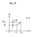
- the characteristic computing section 26 will be described with reference to the phase-wavelength diagram shown in Fig. 13.
- ⁇ i+1- ⁇ i is represented by ⁇
- the group delay time is computed from ⁇ and the modulation frequency fi, and then the wavelength dispersion is computed therefrom.
- the range of phase difference that can be measured from the phase comparator 24 extends from - ⁇ to ⁇ . Therefore, it is preferable that ⁇ i+1- ⁇ i would be within the range extending from - ⁇ to ⁇ . This is because any large modulation frequency fi can easily exceed the range of - ⁇ to ⁇ . In other words, when the same time difference is expressed by the phase difference, the bigger the frequency is, the cycle is shorter, and when it is expressed by the phase difference, the cycle will be longer. For example, when the time difference is 1/50 secs., if the frequency is 1 Hz, the range of phase difference is only 0.04 ⁇ , but if the frequency is 50Hz, it will be 2 ⁇ . Therefore, the modulation frequency fi should be lowered to the minimum possible, and the wavelength ⁇ of the incident light should be varied.
- the modulation frequency fi has a high value. This is due to the fact that, when a same time difference is expressed with a phase difference, the larger the frequency is, the shorter the cycle becomes, and when it is expressed with a phased difference, the cycle will be greater.
- the present invention has an object of providing devices enabling to enlarge the modulation frequency that modulates a variable length wavelength generated by the light source without making problem with respect to the measurement of the optical characteristic.
- an apparatus for measuring the characteristics of device under test that transmits light includes: a variable wavelength light source for generating a variable wavelength light; a wavelength setting unit for setting the variable wavelength light at a first wavelength and a second wavelength; an initial modulation frequency setting unit for setting the initial modulation frequency for modulation; a modulating signal generating unit for generating a modulating signal of a set modulation frequency; an optical modulating unit for receiving the input of the modulating signal and modulating the variable wavelength light with the frequency of the modulating signal; a phase measuring unit for measuring a first phase of a transmitted light, which is obtained by the transmission through the device under test of an incident light having the first wavelength and a second phase of the transmitted light, which is obtained by the transmission through the device under test of an incident light having the second wavelength; a modified modulation frequency computing unit for computing a modified modulation frequency by multiplying the value, which is obtained by dividing the given phase value by the phase difference between the first phase and the second phase, by the initial modulation frequency; and
- the initial modulation frequency is limited to a small value to insure that the phase difference between the first phase and the second phase will be less than the given phase value, for example, ⁇ .
- the modified modulation frequency computing unit enables to compute a modified modulation frequency that causes the phase difference between the transmitted light corresponding to the first wavelength and the transmitted light corresponding to the second wavelength to coincide with the given phase value. Therefore, if the frequency modulating the incident light is chosen as the modified modulation frequency by the modified modulation frequency setting unit, the phase difference between the transmitted light corresponding to the first wavelength and the transmitted light corresponding to the second wavelength will be the given phase value. Therefore, it is possible to measure the phase difference. And further as the frequency for modulating the incident light can be increased, the measurement precision of the phase difference can be improved.
- the present invention as described in claim 2, is the optical characteristic measuring apparatus according to claim 1, wherein the initial modulation frequency setting unit sets the minimum initial modulation frequency and the initial modulation frequencies other than the minimum initial modulation frequency; the modified modulation frequency computing unit computes a modified modulation frequency by multiplying by the minimum initial modulation frequency the value obtained by dividing the given phase value by the phase difference between the first phase and the second phase of the transmitted light resulting from the transmission through the device under test of the incident light modulated by the minimum initial modulation frequency; and the modified modulation frequency setting unit sets the maximum the initial modulation frequency among the initial modulation frequencies equal to or below the modified modulation frequencies as the frequency of the modulating signal.
- the initial modulation frequency is limited to a small value to insure that the phase difference between the first phase and the second phase will be less than the given phase value, for example, ⁇ .
- the modified modulation frequency computing unit enables to compute a modified modulation frequency that causes the phase difference between the transmitted light corresponding to the first wavelength and the transmitted light corresponding to the second wavelength to coincide with the given phase value. Therefore, if the maximum initial modulation frequency among the initial modulation frequencies below the modified modulation frequency is set as the modified modulation frequency by the modified modulation frequency setting unit, the phase difference between the transmitted light corresponding to the first wavelength and the transmitted light corresponding to the second wavelength will be the given phase value. Therefore, it is possible to measure the phase difference. And further as the frequency for modulating the incident light can be increased, the measurement precision of the phase difference can be improved.
- the present invention as described in claim 3, is the optical characteristic measuring apparatus according to claim 1 or 2, wherein there are a plurality of first wavelengths and a plurality of second wavelengths.
- the present invention as described in claim 4 is the optical characteristic measuring apparatus according to claim 3 wherein, the intervals between the first wavelength and the second wavelength are equal, and the second wavelength is taken as the first wavelength and furthermore another second wavelength is taken so that the intervals between the first wavelength and the second wavelength are equal.
- the present invention as described in claim 5, is the optical characteristics measuring apparatus according to claim 3 or 4, wherein after completing the setting of the first wavelength and the second wavelength, the modified modulation frequency setting unit sets the modified modulation frequency as the frequency of the modulating signal.
- the present invention as described in claim 6, is the optical characteristics measuring apparatus according to claim 3 or 4, wherein every time when the first wavelength and the second wavelength are set, the modified modulation frequency setting unit sets the modified modulation frequency as the frequency of the modulating signal.
- the optical characteristics measuring apparatus includes an optical/electrical conversion unit for outputting electrical signals obtained by optical/electrical conversion of the transmitted light to the phase measuring unit.
- the present invention as described in claim 8, is the optical characteristics measuring apparatus according to either one of claims 1 to 6, wherein the phase measuring unit measures the phase difference between the modulating signal and the transmitted light.
- the optical characteristics measuring apparatus includes a characteristic computing unit for computing the group delay or the wavelength dispersion of the device under test by unit of the phase difference measured by the phase measuring unit.
- a method for measuring the characteristics of device under test that transmits light includes: a variable wavelength light generating step for generating a variable wavelength light; a wavelength setting step for setting the variable wavelength light at a first wavelength and a second wavelength; an initial modulation frequency setting step for setting the initial modulation frequency for modulation; a modulating signal generating step for generating a modulating signal of a set modulation frequency; an optical modulating step for receiving the input of the modulating signal and modulating the variable wavelength light with the frequency of the modulating signal; a phase measuring step for measuring the first phase of the transmitted light, which is obtained by the transmission through the device under test of an incident light having the first wavelength and the second phase of the transmitted light, which is obtained by the transmission through the device under test of an incident light having the second wavelength; a modified modulation frequency computing step for computing a modified modulation frequency by multiplying the value, which is obtained by dividing the given phase value by the phase difference between the first phase and the second phase, by the initial modulation frequency; and
- the present invention as described in claim 11, is the optical characteristic measuring method according to claim 10, wherein the initial modulation frequency setting step sets the minimum initial modulation frequency and the initial modulation frequencies other than the minimum initial modulation frequency; the modified modulation frequency computing step computes a modified modulation frequency by multiplying by the minimum initial modulation frequency the value obtained by dividing the given phase value by the phase difference between the first phase and the second phase of the transmitted light resulting from the transmission through the device under test of the incident light modulated by the minimum initial modulation frequency; and the modified modulation frequency setting step sets the maximum the initial modulation frequency among the initial modulation frequencies equal to or below the modified modulation frequencies as the frequency of the modulating signal.
- the present invention as described in claim 12, is a computer-readable medium having a program of instructions for execution by the computer to perform a characteristics measuring process for measuring characteristics of device under test that transmits light, the characteristics measuring process including: a variable wavelength light generating process for generating a variable wavelength light; a wavelength setting process for setting the variable wavelength light at a first wavelength and a second wavelength; an initial modulation frequency setting process for setting the initial modulation frequency for modulation; a modulating signal generating process for generating a modulating signal of a set modulation frequency; an optical modulating process for receiving the input of the modulating signal and modulating the variable wavelength light with the frequency of the modulating signal; a phase measuring process for measuring the first phase of the transmitted light, which is obtained by the transmission through the device under test of an incident light having the first wavelength and the second phase of the transmitted light, which is obtained by the transmission through the device under test of an incident light having the second wavelength; a modified modulation frequency computing process for computing a modified modulation frequency by multiplying the value, which is obtained by dividing the
- the present invention as described in claim 13, is the computer-readable medium according to claim 12, wherein the initial modulation frequency setting process sets the minimum initial modulation frequency and the initial modulation frequencies other than the minimum initial modulation frequency; the modified modulation frequency computing process computes a modified modulation frequency by multiplying by the minimum initial modulation frequency the value obtained by dividing the given phase value by the phase difference between the first phase and the second phase of the transmitted light resulting from the transmission through the device under test of the incident light modulated by the minimum initial modulation frequency; and the modified modulation frequency setting process sets the maximum the initial modulation frequency among the initial modulation frequencies equal to or below the modified modulation frequencies as the frequency of the modulating signal.
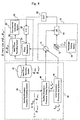
- Fig. 1 is a block diagram showing the configuration of the optical characteristic measuring apparatus related to the first preferred embodiment of the present invention.
- the optical characteristic measuring apparatus related to the preferred embodiments of the present invention includes a light source system 10 for introducing light to the DUT 30, a characteristic measuring system 20 for receiving light having transmitted the DUT 30 and measuring the characteristics of the DUT 30, and a modulation frequency setting system 40 for setting the modulation frequency.
- the light source system 10 includes a variable wavelength light source 12, an optical modulator 14, a modulating power source 16, and a wavelength setting section 18.
- the variable wavelength light source 12 generates a variable wavelength light.
- the wavelength of the variable wavelength light varies discretely by means of the wavelength setting section 18 between the first wavelength of ⁇ i and the second wavelength of ⁇ i+1.
- the light modulator 14 modulates the variable wavelength light with the frequency of electrical signals generated by the modulation power supply 16 and supplies the variable wavelength light to the DUT 30.
- the light modulator 14 includes LN (lithium niobate).
- the modulation power source 16 generates electrical signals for modulating the frequencies set by the modulation frequency setting system 40.
- the electrical signals for modulation are supplied to the light modulator 14 and the phase comparator 24 described below.
- the wavelength setting section 18 sets discretely the wavelength of variable wavelength lights at the first wavelength ⁇ i and the second wavelength ⁇ i+1.
- the DUT 30 is for example an optical fiber.
- the incident light supplied to the DUT 30 transmits the DUT 30.
- the incident light transmitting the DUT 30 is called "transmitted light.”
- the characteristic measuring system 20 includes an optical/electrical converter 22, a phase comparator 24, a characteristic computing section 26 and a modified phase recording section 28.
- the optical/electrical converter 22 converts the transmitted light through the optical/electrical conversion process and generates electrical signals which are outputted to the phase comparator 24.
- the phase comparator 24 measures the phase difference between the electrical signals obtained by converting the transmitted light through the optical/electrical conversion process and the electrical signals for modulation.
- the modified phase recording section 28 records the first modified phase ⁇ i and the second modified phase ⁇ i+1 respectively corresponding to the first wavelength ⁇ i and the second wavelength ⁇ i+1 of the incident light when the modified modulation frequency setting section 46 described later sets the frequency of the modulation power source 16 at fi.
- the characteristic computing section 26 computes the group delay characteristic and the wavelength dispersion characteristic of the DUT 30 from the first modified phase ⁇ i and the second modified phase ⁇ i+1 recorded at the modified phase recording section 28.
- the group delay characteristic can be computed from the relationship between the phase measured by the phase comparator 24 and the modulation frequency fi.
- the wavelength dispersion characteristic can be obtained by differentiating the group delay characteristic by the wavelength.
- the modulation frequency setting system 40 includes an initial phase recording section 42, a modified modulation frequency computing section 44, a modified modulation frequency setting section 46, and an initial modulation frequency setting section 48.
- the initial phase recording section 42 records the first initial phase ⁇ min_i and the second initial phase ⁇ min_i+1 respectively corresponding to the first wavelength ⁇ i and the second wavelength ⁇ i+1 of the incident light when the initial modulation frequency setting section 48 described later sets the frequency of the modulation power source 16 at fmin.
- the modified modulation frequency computing section 44 computes the modified modulation frequency fi.
- the modified modulation frequency setting section 46 sets the modified modulation frequency fi as the frequency of the electrical signals for modulation generated by the modulation power source 16.
- the initial modulation frequency setting section 48 sets the initial modulation frequency fmin as the frequency of the electrical signals for modulation generated by the modulation power source 16.
- the initial modulation frequency fmin is normally set at a small value so that the difference between the first initial phase ⁇ min_i and the second initial phase ⁇ min_i+1 may be easily contained within a range of - ⁇ to ⁇ or 0 to 2 ⁇ .
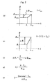
- Fig. 2(a) shows the relationship between the phase and the wavelength when the modulation frequency is the initial modulation frequency fmin.
- Fig. 2 (a) shows, the difference between the first initial phase ⁇ min_i and the second initial phase ⁇ min_i+1 is ⁇ min_i and is small.
- the modulation frequency f is replaced by the modified modulation frequency fi (fi>fmin)
- the difference between the first modified phase ⁇ i and the second modified phase ⁇ i+1 is ⁇ i and is large. This is because, as shown in Fig.
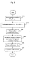
- Fig. 3 is a flow chart showing the operation of the first embodiment.
- the initial modulation frequency setting section 48 sets the initial modulation frequency fmin as the frequency of the electrical signals for modulation generated by the modulation power source 16 (S10).
- the wavelength setting section 18 sets the frequency of the variable wavelength light generated by the variable wavelength light source 12 at the first wavelength ⁇ i and the second wavelength ⁇ i+1.
- the light modulator 14 is supplied with the electrical signals for modulation generated by the modulation power source 16.
- the variable wavelength light is modulated by the frequency fmin of the electrical signals for modulation at the light modulator 14 to be supplied to the DUT 30.
- the transmitted light that has transmitted the DUT 30 is converted by the optical/electrical conversion process by the optical/electrical converter 22 to be supplied to the phase comparator 24.
- the phase comparator 24 measures the phase differences between the phase of the electrical signals outputted by the optical/electrical converter 22 and the phase of the electrical signals for modulation generated by the modulation power source 16. These phase differences are the first initial phase ⁇ min_i and the second initial phase ⁇ min_i+1.
- the phase comparator 24 measures the first initial phase ⁇ min_i and the second initial phase ⁇ min_i+1 (S12).
- the first initial phase ⁇ min_i and the second initial phase ⁇ min_i+1 are recorded at the initial phase recording section 42.
- the modified modulation frequency computing section 44 reads the first initial phase ⁇ min_i and the second initial phase ⁇ min_i+1 from the initial phase recording section 42 and computes a modified modulation frequency fi (S14).
- the modified modulation frequency fi can be computed by using the formula shown in Fig. 2(d) when it is desired to limit ⁇ i at a value equal to or less than ⁇ . If it is desired to keep ⁇ i at a given value other than ⁇ , it is possible to compute the value of the modified modulation frequency fi by multiplying the given value by fmin/ ⁇ min as shown in Fig. 2(e).
- the modified modulation frequency fi is sent from the modified modulation frequency computing section 44 to the modified modulation frequency setting section 46.
- the modified modulation frequency setting section 46 sets the modified modulation frequency fi as the frequency of the electrical signals for modulation generated by the modulation power source 16 (S16).
- the wavelength setting section 18 sets the wavelength of the variable wavelength light generated by the variable wavelength light source 12 at the first wavelength ⁇ i and the second wavelength ⁇ i+1.
- the light modulator 14 is supplied with the electrical signals for modulation generated by the modulation power source 16.
- the variable wavelength light is modulated with the frequency fi of the electrical signals for modulation at the light modulator 14 to be supplied to the DUT 30.
- the transmitted light having transmitted the DUT 30 is converted by the optical/electrical conversion process by the optical/electrical converter 22 to be supplied to the phase comparator 24.
- the phase comparator 24 measures the phase differences between the phase of the electrical signals outputted by the optical/electrical converter 22 and the phase of the electrical signals for modulation generated by the modulation power source 16.
- phase differences are the first initial phase ⁇ i and the second initial phase ⁇ i+1.
- the phase comparator 24 seeks the first modified phase ⁇ i and the second modified phase ⁇ i+1 (S17).
- the first modified phase ⁇ i and the second modified phase ⁇ i+1 are recorded at the modified phase recording section 28.
- the characteristic computing section 26 reads the first modified phase ⁇ i and the second modified phase ⁇ i+1 from the modified phase recording section 28 to compute the group delay or the wavelength dispersion of the DUT 30 (S18).
- the modified modulation frequency computing section 46 it is possible to compute by means of the modified modulation frequency computing section 46 a modified modulation frequency fi that will leave the phase difference between the first modified phase ⁇ i and the second modified phase ⁇ i+1 at a given phase value, for example at a value equal to or less than ⁇ . Therefore, if the frequency for modulating the incident light is set at the modified modulation frequency fi by the modified modulation frequency setting section 46, the phase difference between the first modified phase ⁇ i and the second modified phase ⁇ i+1 will be the required phase value ⁇ , and thus the phase difference can be measured. Moreover, as the frequency for modulating the incident light can be sufficiently large, the measure precision of the phase difference can be enhanced.
- the second preferred embodiment is different from the first preferred embodiment in that the modified modulation frequency fi itself is not chosen as the frequency of the electrical signals for modulation.
- Fig. 4 is a block diagram showing the configuration of an optical characteristic measuring apparatus relating to the second preferred embodiment of the present invention.
- the optical characteristic measuring apparatus relating to the preferred embodiment includes a light source system 10 introducing light into the DUT 30, a characteristic measuring system 20 for receiving the light having transmitted the DUT 30 and measuring the characteristics of the DUT 30, and a modulation frequency setting system 40 for setting the modulation frequency.
- the light source system 10 includes a variable wavelength light source 12, a light modulator 14, a modulation power source 16 and a wavelength setting section 18.
- the variable wavelength light source 12 generates variable wavelength light.
- the wavelength of the variable wavelength light varies discretely such as the first wavelength ⁇ i and the second wavelength ⁇ i+1 by the operation of the wavelength setting section 18.
- the light modulator 14 modulates the variable wavelength light by the frequency of the electrical signals generated by the modulation power source 16 which will be supplied to the DUT 30.
- the light modulator 14 includes LN (lithium niobate).
- the modulation power source 16 generates electrical signals for modulating the frequencies set by the modulation frequency setting system 40.
- the electrical signals for modulation is supplied to the light modulator 14 and the phase comparator 24 described later.
- the wavelength setting section 18 sets discretely the frequency of variable wavelength light, for example, at the first wavelength ⁇ i and at the second wavelength ⁇ i+1.
- the DUT 30 is for example an optical fiber.
- the incident light supplied to the DUT 30 transmits the DUT 30.
- the incident light transmitting the DUT 30 is called "transmitted light.”
- the characteristic measuring system 20 includes an optical/electrical converter 22, a phase comparator 24, a characteristic computing section 26 and a modified phase recording section 28.
- the optical/electrical converter 22 converts the transmitted light by the optical/ electrical conversion process and generates electrical signals which will then be supplied to the phase comparator 24.
- the phase comparator 24 measures the phase difference between the electrical signals obtained by converting by the optical/electrical conversion process the transmitted light and the electrical signals for modulation.
- the modified phase recording section 28 records the first modified phase ⁇ i and the second modified phase ⁇ i+1 respectively corresponding to the first wavelength ⁇ i and the second wavelength ⁇ i+1 of the incident light when the modified modulation frequency setting section 46 sets the frequency of the modulation power source 16 at any one of fai, fbi, .... Incidentally, fai, fbi, ... will be described later.
- the characteristic computing section 26 computes the group delay characteristic and the wavelength dispersion characteristic of the DUT 30 from the first modified phase ⁇ i and the second modified phase ⁇ i+1 recorded in the modified phase recording section 28.
- the group delay characteristic can be computed from the relationship between the phase measured by the phase comparator 24 and the modified frequency (any one of fai, fbi, ).
- the wavelength dispersion characteristic can be computed by differentiating the group delay characteristic by the wavelength.
- the modulation frequency setting system 40 includes an initial phase recording section 42, a modified modulation frequency computing section 44, a modified modulation frequency setting section 46, and an initial modulation frequency setting section 48.
- the initial phase recording section 42 records the first initial phase ⁇ min_i and the second initial phase ⁇ min_i+1 respectively corresponding to the first wavelength ⁇ i and the second wavelength ⁇ i+1 of the incident light when the initial modulation frequency setting section 48 described later sets the frequency of the modulation power source 16 at fmin.
- the modified modulation frequency computing section 44 computes the modified modulation frequency fi.
- the modified modulation frequency setting section 46 sets the maximum below the modified modulation frequency fi within fai, fbi, ... as the frequency of the electrical signals for modulation generated by the modulation power source 16.
- the initial modulation frequency setting section 48 sets the initial modulation frequencies fmin, fai, fbi, ... as the frequency of the electrical signals for modulation generated by the modulation power source 16.
- the initial modulation frequency fmin is normally set at a small value so that the difference between the first initial phase ⁇ min_i and the second initial phase ⁇ min_i+1 may be contained with sufficient margin within the range between - ⁇ and ⁇ or between 0 and 2 ⁇ .
- fai, fbi, ... are set at a larger value than fmin. For this reason, the initial modulation frequency fmin is called the minimum initial modulation frequency fmin.
- Fig. 2(a) shows the relations between the phase and the wavelength when the modulation frequency f is the initial modulation frequency fmin.
- Fig. 2(a) shows, the difference between the first initial phase ⁇ min_i and the second initial phase ⁇ min_i+1 is ⁇ min_i and is small.
- the modulation frequency f is replaced by the modified modulation frequency fi (fi>fmin), as shown in Fig.
- the modified modulation frequency setting section 46 sets the maximum below the modified modulation frequency fi among fai, fbi, ... as the modulation frequency.
- the modulation of the incident light by means of such a modulation frequency will produce the maximum value at or below ⁇ for the phase difference between the first modified phase ⁇ i and the second modified phase ⁇ i+1, which will be larger than the phase difference ⁇ min_i for the initial phase.
- Fig. 5 is a flow chart showing the operation of the second embodiment.
- the initial modulation frequency setting section 48 sets the initial modulation frequencies fmin, fai, fbi, ... as the frequency of the electrical signals for modulation generated by the modulation power source 16 (S11).
- the wavelength setting section 18 sets the wavelength of the variable wavelength light generated by the variable wavelength light source 12 at the first wavelength ⁇ i and the second wavelength ⁇ i+1.
- the light modulator 14 is supplied with the electrical signals for modulation generated by the modulation power source 16.
- the variable wavelength light is modulated by the frequency fmin, fai, fbi, ... of the electrical signals for modulation at the light modulator 14 and is supplied to the DUT 30.
- the transmitted light that has transmitted the DUT 30 is converted by the optical/electrical conversion process by the optical/electrical converter 22 to be supplied to the phase comparator 24.
- the phase comparator 24 measures the phase differences between the phase of the electrical signals outputted by the optical/electrical converter 22 and the phase of the electrical signals for modulation generated by the modulation power source 16.
- phase differences corresponding to the incident light modulated by the minimum initial modulation frequency fmin are the first initial phase ⁇ min_i and the second initial phase ⁇ min_i+1.
- the phase differences measured by the phase comparator 24 are ⁇ ai, ⁇ bi, ....
- the phase comparator 24 computes the first initial phase ⁇ min_i, the second initial phase ⁇ min_i+1 and the initial phases ⁇ ai, ⁇ bi, ... (S13).
- the first initial phase ⁇ min_i and the second initial phase ⁇ min_i +1 are recorded in the initial phase recording section 42.
- the initial phases ⁇ ai, ⁇ bi, ... are recorded in the modified phase recording section 28.
- the wavelengths of the variable wavelength light are set at the first wavelength ⁇ i and the variable frequencies are switched from fmin to fai, fbi, fci, ....
- the first initial phase ⁇ min_i and the initial phases ⁇ ai, ⁇ bi, ⁇ ci, ... are measured (S13a).
- S13a means the first step of S13 shown in Fig. 5.
- the wavelength of the variable wavelength light is set at the second wavelength of ⁇ i+1, and the second initial phase ⁇ min_i+1 is measured (S13b).
- S13b means the last step of S13 shown in Fig. 5.
- the modified modulation frequency computing section 44 reads the first initial phase ⁇ min_i and the second initial phase ⁇ min_i+1 from the initial phase recording section 42, and computes the modified modulation frequency fi (S14).
- the modified modulation frequency fi can be computed by means of the formula shown in Fig. 2(d). If it is desired to contain ⁇ i at a value other than ⁇ , it is possible to compute the modified modulation frequency fi by multiplying the given value by fmin/ ⁇ min as shown in Fig. 2(e).
- the modified modulation frequency fi is sent from the modified modulation frequency computing section 44 to the modified modulation frequency setting section 46. And equally the initial modulation frequencies fmin, fai, fbi, ... are sent from the initial modulation frequency setting section 48 to the modified modulation frequency setting section 46. There, the modified modulation frequency setting section 46 sets the maximum frequency at or below the modified modulation frequency fi among the initial modulation frequencies fmin, fai, fbi, ... as the frequency of the electrical signals for modulation generated by the modulation power source 16 (S20). For example, fai ⁇ fbi ⁇ fi ⁇ fci. In such a case, as shown in Fig. 6, the modified modulation frequency setting section 46 sets fbi as the frequency of the electrical signals for modulation generated by the modulation power source 16.
- the wavelength setting section 18 sets the wavelength of the variable wavelength light generated by the variable wavelength light source 12 at the second wavelength ⁇ i+1.
- the light modulator 14 is supplied with the electrical signals for modulation generated by the modulation power source 16.
- the variable wavelength light is modulated at the light modulator 14 by the frequency set by the modified modulation frequency setting section 46 (any one among fai, fbi, ...) of the electrical signals for modulation and is supplied to the DUT 30.
- the transmitted light that has transmitted the DUT 30 is converted by the optical/electrical conversion process by the optical/electrical converter 22 and is supplied to the phase comparator 24.
- the phase comparator 24 measures the phase differences between the phase of the electrical signals outputted by the optical/electrical converter 22 and the phase of the electrical signals for modulation generated by the modulation power source 16. This phase difference is the second modified phase ⁇ i+1. Namely, the phase comparator 24 computes the second modified phase ⁇ i+1 (S22).
- phase comparator 24 computes the second modified phase ⁇ i+1.
- the modified modulation frequency setting section 46 has set fbi as the frequency of the electrical signals for modulation generated by the modulation power source 16.
- the phase comparator 24 computes the second modified phase ⁇ i+1 (S22).
- the phase at the time when the modulation frequency is fbi and the wavelength of the variable wavelength light is ⁇ i+1 is measured.
- the phase at the time when the wavelength of the variable wavelength light is the second wavelength ⁇ i+1 is not measured.
- the second modified phase ⁇ i+1 is recorded in the modified phase recording section 28.
- the first modified phase ⁇ i corresponds to the modulation frequency set by the modified modulation frequency setting section 46 among the initial phases ⁇ ai, ⁇ bi, ....
- the modified modulation frequency setting section 46 has set fbi as the modulation frequency as shown in Fig. 6, the first modified phase ⁇ i is the initial phase ⁇ bi. Therefore, we can assume that the first modified phase ⁇ i has already been recorded in the modified phase recording section 28. Therefore, the characteristic computing section 26 reads the first modified phase ⁇ i and the second modified phase ⁇ i+1 from the modified phase recording section 28 and computes the group delay or the wavelength dispersion of the DUT 30 (S24).
- the modified modulation frequency computing section 46 it is possible to compute by means of the modified modulation frequency computing section 46 a modified modulation frequency fi so that the phase difference between the first modified phase ⁇ i and the second modified phase ⁇ i+1 could be equal to or below the given phase value, for example ⁇ .
- the maximum frequency equal to or below the modified modulating frequency fi among the initial modulation frequencies fai, fbi, ... is adopted for the frequency for modulating the incident light by the modified modulation frequency setting section 46, the phase difference between the first modified phase ⁇ i and the second modified phase ⁇ i+1 is equal to or below the given phase value ⁇ , and therefore it is possible to measure the phase difference.
- the possibility of choosing a sufficiently wide frequency for modulating the incident light enables to enhance the precision of measurements.
- the fact that the wavelength of the variable wavelength light is changed for once can economize the time required for changing wavelength. For example, let us suppose that it takes about 3 secs to change the wavelength of the variable wavelength light and about 10 ms to change the modulation frequency. Then, as the time required to change the wavelength is considerably longer than that to change the modulation frequency, it is effective to economize the time required to change the wavelength.
- the third preferred embodiment is different in that there are three or more wavelengths of the variable wavelength light set by the wavelength setting section 18.
- Fig. 7 shows the relationship between the phase measured by the phase comparator 24 and the wavelength of the variable wavelength light when there are three or more wavelengths of the variable wavelength light.
- the wavelength of the variable wavelength light varies within a range between ⁇ 1 and ⁇ n.
- ⁇ 1, ⁇ 2, ⁇ 3, ⁇ ⁇ i, ⁇ i+1, ⁇ ⁇ n are at equal intervals.
- the second wavelength being represented by ⁇ 2.
- ⁇ 2 is taken as the first wavelength
- Such a method of setting the wavelength of variable wavelength light is common with the third through sixth embodiments.
- the configuration of the third embodiment is similar to that of the first embodiment, and its description is omitted.
- Fig. 8 is a flowchart showing the operation of the third embodiment.
- the argument i for deciding the type of the wavelength ⁇ is set at 1 (S30). Then, the question of whether the argument i plus 1 has exceeded n is determined (S32). If the argument i plus 1 has not exceeded n (S32, No), the initial modulation frequency setting section 48 sets the initial modulation frequency fmin as the frequency of the electrical signals for modulation generated by the modulation power source 16 (S10). And the wavelength setting section 18 sets the wavelength of the variable wavelength light generated by the variable wavelength light source 12 at the first wavelength ⁇ i and the second wavelength ⁇ i+1.
- the light modulator 14 is supplied with the electrical signals for modulation generated by the modulation power source 16.
- the variable wavelength light is modulated by the frequency fmin of the electrical signals for modulation at the light modulator 14 and is supplied to the DUT 30.
- the transmitted light that has transmitted the DUT 30 is converted by the optical/electrical conversion process by the optical/electrical converter 22 and is supplied to the phase comparator 24.
- the phase comparator 24 measures the phase differences between the phase of the electrical signals outputted by the optical/electrical converter 22 and the phase of the electrical signals for modulation generated by the modulation power source 16. These phase differences are the first initial phase ⁇ min_i and the second initial phase ⁇ min_i+1.
- the phase comparator 24 computes the first initial phase ⁇ min_i and the second initial phase ⁇ min_i+1 (S12).
- the first initial phase ⁇ min_i and the second initial phase ⁇ min_i+1 are recorded in the initial phase recording section 42.
- And 1 is added to the argument i (S34), and the process returns to the determination whether the argument i has exceeded n (S32). If the argument i plus 1 has exceeded n (S32, Yes), the wavelength of the variable wavelength light has been changed, and the argument i for deciding the type of wavelength ⁇ will be again set at 1 (S36). Then, the process returns to the determination of whether the argument i plus 1 has exceeded n (S38). If the argument i plus 1 has not exceeded n (S38, No), the modified modulation frequency computing section 44 reads the first initial phase ⁇ min_i and the second initial phase ⁇ min_i+1 from the initial phase recording section 42 and computes the modified modulation frequency fi (S14).
- the modified modulation frequency fi can be computed by using the formula shown in Fig. 2(d).
- the modified modulation frequency fi can be computed by multiplying the given value by fmin/ ⁇ min as shown in Fig. 2(e).
- the modified modulation frequency fi is sent from the modified modulation frequency. computing section 44 to the modified modulation frequency setting section 46.
- the modified modulation frequency setting section 46 sets the modified modulation frequency fi as the frequency of the electrical signals for modulation generated by the modulation power source 16 (S16).
- the wavelength setting section 18 sets the wavelength of the variable wavelength light generated by the variable wavelength light source 12 at the first wavelength ⁇ i and the second wavelength ⁇ i+1.
- the light modulator 14 is supplied with the electrical signals for modulation generated by the modulation power source 16.
- the variable wavelength light is modulated by the frequency fi of the electrical signals for modulation at the light modulator 14 and is supplied to the DUT 30.
- the transmitted light that has transmitted the DUT 30 is converted by the optical/electrical conversion process by the optical/electrical converter 22 and is supplied to the phase comparator 24.
- the phase comparator 24 measures the phase differences between the phase of the electrical signals outputted by the optical/electrical converter 22 and the phase of the electrical signals for modulation generated by the modulation power source 16.
- phase differences are the first modified phase ⁇ i and the second modified phase ⁇ i+1.
- the phase comparator 24 computes the first modified phase ⁇ i and the second modified phase ⁇ i+1 (S17).
- the first modified phase ⁇ i and the second modified phase ⁇ i+1 are recorded in the modified phase recording section 28.
- the characteristic computing section 26 reads the first modified phase ⁇ i and the second modified phase ⁇ i+1 from the modified phase recording section 28, and computes the group delay or the wavelength dispersion of the DUT 30 (S18).
- the third preferred embodiment it is possible to measure the characteristics of the DUT 30 even if three or more wavelengths of the variable wavelength light are changed.
- the fourth embodiment is different in that it has three or more wavelengths of the variable wavelength light set by the wavelength setting section 18.
- the fourth preferred embodiment is different in that the modified modulation frequency is computed after each setting of the first wavelength ⁇ i and the second wavelength ⁇ i+1.
- the configuration of the fourth preferred embodiment is similar to that of the first embodiment and its description is omitted.
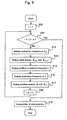
- Fig. 9 is a flowchart showing the operation of the fourth preferred embodiment.
- the argument i for deciding the type of the wavelength ⁇ is set at 1 (S30). Then, the question of whether the argument i plus 1 has exceeded n is determined (S32). If the argument i plus 1 has not exceeded n (S32, No), the initial modulation frequency setting section 48 sets the initial modulation frequency fmin as the frequency of the electrical signals for modulation generated by the modulation power source 16 (S10). And the wavelength setting section 18 sets the wavelength of the variable wavelength light generated by the variable wavelength light source 12 at the first wavelength ⁇ i and the second wavelength ⁇ i+1.
- the light modulator 14 is supplied with the electrical signals for modulation generated by the modulation power source 16.
- the variable wavelength light is modulated by the frequency fmin of the electrical signals for modulation at the light modulator 14 and is supplied to the DUT 30.
- the transmitted light that has transmitted the DUT 30 is converted by the optical/electrical conversion process by the optical/electrical converter 22 and is supplied to the phase comparator 24.
- the phase comparator 24 measures the phase differences between the phase of the electrical signals outputted by the optical/electrical converter 22 and the phase of the electrical signals for modulation generated by the modulation power source 16. These phase differences are the first initial phase ⁇ min_i and the second initial phase ⁇ min_i+1.
- the phase comparator 24 computes the first initial phase ⁇ min_i and the second initial phase ⁇ min_i+1 (S12).
- the first initial phase ⁇ min_i and the second initial phase ⁇ min_i+1 are recorded in the initial phase recording section 42.
- the modified modulation frequency computing section 44 reads the first initial phase ⁇ min_i and the second initial phase ⁇ min_i+1 from the initial phase recording section 42 and computes the modified modulation frequency fi (S14).
- the modified modulation frequency fi can be computed by means of the formula shown in Fig. 2(d). If it is desired to keep ⁇ i at a value other than ⁇ , it is possible to compute the modified modulation frequency fi by multiplying the given value by fmin/ ⁇ min as shown in Fig. 2(e).
- the modified modulation frequency fi is sent from the modified modulation frequency computing section 44 to the modified modulation frequency setting section 46.
- the modified modulation frequency setting section 46 sets the modified modulation frequency fi as the frequency of the electrical signals for modulation generated by the modulation power source 16 (S16).
- the wavelength setting section 18 sets the wavelength of the variable wavelength light generated by the variable wavelength light source 12 at the first wavelength ⁇ i and the second wavelength ⁇ i+1.
- the light modulator 14 is supplied with the electrical signals for modulation generated by the modulation power source 16.
- the variable wavelength light is modulated by the frequency fi of the electrical signals for modulation at the light modulator 14 and is supplied to the DUT 30.
- the transmitted light that has transmitted the DUT 30 is converted by the optical/electrical conversion process by the optical/electrical converter 22 and is supplied to the phase comparator 24.
- the phase comparator 24 measures the phase differences between the phase of the electrical signals outputted by the optical/electrical converter 22 and the phase of the electrical signals for modulation generated by the modulation power source 16.
- phase differences are the first modified phase ⁇ i and the second modified phase ⁇ i+1.
- the phase comparator 24 computes the first modified phase ⁇ i and the second modified phase ⁇ i+1 (S17).
- the first modified phase ⁇ i and the second modified phase ⁇ i+1 are recorded in the modified phase recording section 28.
- the characteristic computing section 26 reads the first modified phase ⁇ i and the second modified phase ⁇ i+1 from the modified phase recording section 28, and computes the group delay or the wavelength dispersion of the DUT 30 (S18).
- the fourth preferred embodiment it is possible to measure the characteristics of the DUT 30 even if three or more wavelengths of the variable wavelength light are changed.
- the fifth preferred embodiment is different in that it has three or more wavelengths of the variable wavelength light set by the wavelength setting section 18.
- the configuration of the fifth preferred embodiment is similar to that of the second embodiment and its description is omitted.
- Fig. 10 is a flowchart showing the operation of the fifth preferred embodiment.
- the argument i for deciding the type of the wavelength ⁇ is set at 1 (S30). Then, the question of whether the argument i plus 1 has exceeded n is determined (S32). If the argument i plus 1 has not exceeded n (S32, No), the initial modulation frequency setting section 48 sets the initial modulation frequencies fmin, fai, fbi, ... as the frequencies of the electrical signals for modulation generated by the modulation power source 16 (S11).
- the wavelength setting section 18 sets the wavelength of the variable wavelength light generated by the variable wavelength light source 12 at the first wavelength ⁇ i and the second wavelength ⁇ i+1.
- the light modulator 14 is supplied with the electrical signals for modulation generated by the modulation power source 16.
- the variable wavelength light is modulated by the frequencies fmin, fai, fbi, ... of the electrical signals for modulation at the light modulator 14 and is supplied to the DUT 30.
- the transmitted light that has transmitted the DUT 30 is converted by the optical/electrical conversion process by the optical/electrical converter 22 and is supplied to the phase comparator 24.
- the phase comparator 24 measures the phase differences between the phase of the electrical signals outputted by the optical/electrical converter 22 and the phase of the electrical signals for modulation generated by the modulation power source 16.
- phase differences corresponding to the incident light modulated by the minimum initial modulation frequency fmin are the first initial phase ⁇ min_i and the second initial phase ⁇ min_i+1.
- phase differences measured by the phase comparator 24 when the wavelength of the variable wavelength light is the first wavelength ⁇ i and the frequencies of the electrical signals for modulation are fai, fbi, ... are ⁇ ai, ⁇ bi, ...
- the phase comparator 24 computes the first initial phase ⁇ min_i, the second initial phase ⁇ min_i+1 and the initial phases ⁇ ai, ⁇ bi, ... (S13).
- the first initial phase ⁇ min_i and the second initial phase ⁇ min_i+1 are recorded in the initial phase recording section 42.
- the initial phases ⁇ ai, ⁇ bi, ... are recorded in the modified phase recording section 28.
- the frequencies of the variable wavelength light are set at the first wavelength ⁇ i and the variable frequencies are switched from fmin to fai, fbi, fci, ....
- the first initial phase ⁇ min_i and the initial phases ⁇ ai, ⁇ bi, ⁇ ci, ... are measured (S13a).
- S13a means the first step of S13 shown in Fig. 5.
- the frequency of the variable wavelength light is set at the second wavelength ⁇ i+1, and the second initial phase ⁇ min_i+1 is measured (S13b).
- S13b means the last step of S13 shown in Fig. 5.
- the modified modulation frequency fi can be computed by using the formula shown in Fig. 2(d).
- the modified modulation frequency fi can be computed by multiplying the given value by fmin/ ⁇ min as shown in Fig. 2(e).
- the modified modulation frequency fi is sent from the modified modulation frequency computing section 44 to the modified modulation frequency setting section 46. And equally the initial modulation frequencies fmin, fai, fbi, ... are sent from the initial modulation frequency setting section 48 to the modified modulation frequency setting section 46. There, the modified modulation frequency setting section 46 sets the maximum frequency at or below the modified modulation frequency fi among the initial modulation frequencies fmin, fai, fbi, ... as the frequency of the electrical signals for modulation generated by the modulation power source 16 (S20). For example, fai ⁇ fbi ⁇ fi ⁇ fci. In such a case, as shown in Fig. 6, the modified modulation frequency setting section 46 sets fbi as the frequency of the electrical signals for modulation generated by the modulation power source 16.
- the wavelength setting section 18 sets the wavelength of the variable wavelength light generated by the variable wavelength light source 12 at the second wavelength ⁇ i+1.
- the light modulator 14 is supplied with the electrical signals for modulation generated by the modulation power source 16.
- the variable wavelength light is modulated by the frequency (any one of fai, fbi, ... ) set by the modified modulation frequency setting section 46 at the light modulator 14 and is supplied to the DUT 30.
- the transmitted light that has transmitted the DUT 30 is converted by the optical/electrical conversion process by the optical/electrical converter 22 and is supplied to the phase comparator 24.
- the phase comparator 24 measures the phase differences between the phase of the electrical signals outputted by the optical/electrical converter 22 and the phase of the electrical signals for modulation generated by the modulation power source 16. This phase difference is the second modified phase ⁇ i+1. In other words, the phase comparator 24 computes the second modified phase ⁇ i+1 (S22). At this point, the second modified phase ⁇ i+1 is recorded at the modified phase recording section 28.
- phase comparator 24 computes the second modified phase ⁇ i+1.
- the modified modulation frequency setting section 46 has set fbi as the frequency of the electrical signals for modulation generated by the modulation power source 16.
- the phase comparator 24 computes the second modified phase ⁇ i+1 (S22).
- the second wavelength ⁇ i+1 since the second wavelength ⁇ i+1 has been chosen as the wavelength of the variable wavelength light, the phase at the time when the modulation frequency is fbi and the wavelength of the variable wavelength light is ⁇ i+1 will be measured.
- f fbi
- the phase at the time when the wavelength of the variable wavelength light is the second wavelength ⁇ i+1 will not be measured.
- the first modified phase ⁇ i corresponds to the modulation frequency set by the modified modulation frequency setting section 46 among the initial phase ⁇ ai, ⁇ bi, ... set by the modified modulation frequency setting section 46.
- the modified modulation frequency setting section 46 sets fbi as the modulation frequency as shown in Fig. 6, the first modified phase ⁇ i will be the initial phase ⁇ bi.
- the characteristic computing section 26 reads the first modified phase ⁇ i and the second modified phase ⁇ i+1 from the modified phase recording section 28, and computes the group delay or the wavelength dispersion of the DUT 30 (S24).
- the fifth preferred embodiment it is possible to measure the characteristics of the DUT 30 even if three or more wavelengths of the variable wavelength light are changed.
- the sixth preferred embodiment is different in that it has three or more wavelengths of the variable wavelength light set by the wavelength setting section 18.
- the sixth preferred embodiment is different in that the modified modulation frequency is computed after each setting of the first wavelength ⁇ i and the second wavelength ⁇ i+1.
- the configuration of the sixth preferred embodiment is similar to that of the second embodiment and its description is omitted.
- Fig. 11 is a flowchart showing the operation of the sixth preferred embodiment.
- the argument i for deciding the type of the wavelength ⁇ is set at 1 (S30). Then, the question of whether the argument i plus 1 has exceeded n is determined (S32). If the argument i plus 1 has not exceeded n (S32, No), the initial modulation frequency setting section 48 sets the initial modulation frequencies fmin, fai, fbi, ... as the frequencies of the electrical signals for modulation generated by the modulation power source 16 (S11).
- the wavelength setting section 18 sets the wavelength of the variable wavelength light generated by the variable wavelength light source 12 at the first wavelength ⁇ i and the second wavelength ⁇ i+1.
- the light modulator 14 is supplied with the electrical signals for modulation generated by the modulation power source 16.
- the variable wavelength light is modulated by the frequencies fmin, fai, fbi, ... of the electrical signals for modulation at the light modulator 14 and is supplied to the DUT 30.
- the transmitted light that has transmitted the DUT 30 is converted by the optical/electrical conversion process by the optical/electrical converter 22 to be supplied to the phase comparator 24.
- the phase comparator 24 measures the phase differences between the phase of the electrical signals outputted by the optical/electrical converter 22 and the phase of the electrical signals for modulation generated by the modulation power source 16.
- phase differences corresponding to the incident light modulated by the minimum initial modulation frequency fmin are the first initial phase ⁇ min_i and the second initial phase ⁇ min_i+1.
- phase differences measured by the phase comparator 24 when the wavelength of the variable wavelength light is the first wavelength ⁇ i and the frequencies of the electrical signals for modulation are fai, fbi, ... are ⁇ ai, ⁇ bi, ...
- the phase comparator 24 computes the first initial phase ⁇ min_i, the second initial phase ⁇ min_i+1 and the initial phases ⁇ ai, ⁇ bi, ... (S13).
- the first initial phase ⁇ min_i and the second initial phase ⁇ min_i+1 are recorded in the initial phase recording section 42.
- the initial phases ⁇ ai, ⁇ bi, ... are recorded in the modified phase recording section 28.
- the frequencies of the variable wavelength light are set at the first wavelength ⁇ i and the modulation frequencies are switched from fmin to fai, fbi, fci, ...
- the first initial phase ⁇ min_i and the initial phases ⁇ ai, ⁇ bi, ⁇ ci, ... are measured (S13a).
- S13a means the first step of S13 shown in Fig. 5.
- the wavelength of the variable wavelength light is set at the second wavelength of ⁇ i+1, and the second initial phase ⁇ min_i+1 is measured (S13b).
- S13b means the last step of S13 shown in Fig. 5.
- the modified modulation frequency computing section 44 reads the first initial phase ⁇ min_i and the second initial phase ⁇ min_i+1 from the initial phase recording section 42 and computes the modified modulation frequency fi (S14).
- the modified modulation frequency fi can be computed by means of the formula shown in Fig. 2(d). If it is desired to keep ⁇ i at a value other than ⁇ , it is possible to compute the modified modulation frequency fi by multiplying the given value by fmin/ ⁇ min as shown in Fig. 2(e).
- the modified modulation frequency fi is sent from the modified modulation frequency computing section 44 to the modified modulation frequency setting section 46. And equally the initial modulation frequencies fmin, fai, fbi, ... are sent from the initial modulation frequency setting section 48 to the modified modulation frequency setting section 46. Therefore, the modified modulation frequency setting section 46 sets the maximum frequency at or below the modified modulation frequency fi among the initial modulation frequencies fmin, fai, fbi, ... as the frequency of the electrical signals for modulation generated by the modulation power source 16 (S20). For example, fai ⁇ fbi ⁇ fi ⁇ fci. In such a case, as shown in Fig. 6, the modified modulation frequency setting section 46 sets fbi as the frequency of the electrical signals for modulation generated by the modulation power source 16.
- the wavelength setting section 18 sets the wavelength of the variable wavelength light generated by the variable wavelength light source 12 at the second wavelength ⁇ i+1.
- the light modulator 14 is supplied with the electrical signals for modulation generated by the modulation power source 16.
- the variable wavelength light is modulated by the frequency (any one of fai, fbi, ... ) of the electrical signals for modulation at the light modulator 14 and is supplied to the DUT 30.
- the transmitted light that has transmitted the DUT 30 is converted by the optical/electrical conversion process by the optical/electrical converter 22 to be supplied to the phase comparator 24.
- the phase comparator 24 measures the phase differences between the phase of the electrical signals outputted by the optical/electrical converter 22 and the phase of the electrical signals for modulation generated by the modulation power source 16. This phase difference is the second modified phase ⁇ i+1. In other words, the phase comparator 24 computes the second modified phase ⁇ i+1 (S22). At this point, the second modified phase ⁇ i+1 is recorded at the modified phase recording section 28.
- phase comparator 24 computes the second modified phase ⁇ i+1.
- the modified modulation frequency setting section 46 has set fbi as the frequency of the electrical signals for modulation generated by the modulation power source 16.
- the phase comparator 24 computes the second modified phase ⁇ i+1 (S22).
- the second wavelength ⁇ i+1 since the second wavelength ⁇ i+1 has been chosen as the wavelength of the variable wavelength light, the phase at the time when the modulation frequency is fbi and the wavelength of the variable wavelength light is ⁇ i+1 will be measured.
- f fbi
- the phase at the time when the wavelength of the variable wavelength light is the second wavelength ⁇ i+1 will not be measured.
- the first modified phase ⁇ i corresponds to the modulation frequency among the initial phase ⁇ ai, ⁇ bi, ... set by the modified modulation frequency setting section 46.
- the modified modulation frequency setting section 46 sets fbi as the modulation frequency as shown in Fig. 6, the first modified phase ⁇ i will be the initial phase ⁇ bi.
- the characteristic computing section 26 reads the first modified phase ⁇ i and the second modified phase ⁇ i+1, and computes the group delay or the wavelength dispersion of the DUT 30 (S24).
- the sixth preferred embodiment it is possible to measure the characteristics of the DUT 30 even if three or more wavelengths of the variable wavelength light are changed.
- the embodiment described above can be realized by having a media reading apparatus of a computer provided with a CPU, a hard disk, memory media (a floppy disk, a CD-ROM, etc.) read a program executing various functions described above and installing the program on a hard disk. In this way, the functions described above can be performed.
- the range of frequencies for modulating the incident light can be enlarged and therefore the precision of measuring can be enhanced.
Landscapes
- Physics & Mathematics (AREA)
- Chemical & Material Sciences (AREA)
- Optics & Photonics (AREA)
- Analytical Chemistry (AREA)
- General Physics & Mathematics (AREA)
- Dispersion Chemistry (AREA)
- Testing Of Optical Devices Or Fibers (AREA)
Abstract
Description
Claims (13)
- An apparatus for measuring the characteristics of device under test that transmits light comprising:wherein the characteristics of device under test are measured on the basis of the transmitted light resulting from the transmission through said device under test of the incident light modulated by a frequency set by said modified modulation frequency setting means.a variable wavelength light source for generating a variable wavelength light;a wavelength setting means for setting said variable wavelength light at a first wavelength and a second wavelength;an initial modulation frequency setting means for setting the initial modulation frequency for modulation;a modulating signal generating means for generating a modulating signal of a set modulation frequency;an optical modulating means for receiving the input of said modulating signal and modulating said variable wavelength light with the frequency of said modulating signal;a phase measuring means for measuring a first phase of a transmitted light, which is obtained by the transmission through the device under test of an incident light having the first wavelength and a second phase of said transmitted light, which is obtained by the transmission through the device under test of an incident light having the second wavelength;a modified modulation frequency computing means for computing a modified modulation frequency by multiplying the value, which is obtained by dividing the given phase value by the phase difference between the first phase and the second phase, by said initial modulation frequency; anda modified modulation frequency setting means for setting said modified modulation frequency as the frequency of said modulating signal,
- The optical characteristic measuring apparatus according to claim 1, wherein said initial modulation frequency setting means sets the minimum initial modulation frequency and said initial modulation frequencies other than said minimum initial modulation frequency;said modified modulation frequency computing means computes a modified modulation frequency by multiplying by said minimum initial modulation frequency the value obtained by dividing said given phase value by the phase difference between said first phase and said second phase of said transmitted light resulting from the transmission through said device under test of said incident light modulated by said minimum initial modulation frequency; andsaid modified modulation frequency setting means sets the maximum said initial modulation frequency among said initial modulation frequencies equal to or below said modified modulation frequencies as the frequency of said modulating signal.
- The optical characteristic measuring apparatus according to claim 1 or 2, wherein there are a plurality of first wavelengths and a plurality of second wavelengths.
- The optical characteristic measuring apparatus according to claim 3 wherein, the intervals between said first wavelength and said second wavelength are equal, and
said second wavelength is taken as said first wavelength and furthermore another second wavelength is taken so that the intervals between said first wavelength and said second wavelength are equal. - The optical characteristics measuring apparatus according to claim 3 or 4, wherein after completing the setting of said first wavelength and said second wavelength, said modified modulation frequency setting means sets said modified modulation frequency as the frequency of said modulating signal.
- The optical characteristics measuring apparatus according to claim 3 or 4, wherein every time when said first wavelength and said second wavelength are set, said modified modulation frequency setting means sets said modified modulation frequency as the frequency of said modulating signal.
- The optical characteristics measuring apparatus according to either one of claims 1 to 6, comprising an optical/electrical conversion means for outputting electrical signals obtained by optical/electrical conversion of said transmitted light to said phase measuring means.
- The optical characteristics measuring apparatus according to either one of claims 1 to 6, wherein said phase measuring means measures the phase difference between said modulating signal and said transmitted light.
- The optical characteristics measuring apparatus according to either one of claims 1 to 6, comprising a characteristic computing means for computing the group delay or the wavelength dispersion of said device under test by means of said phase difference measured by said phase measuring means.
- A method for measuring the characteristics of device under test that transmits light comprising:wherein the characteristics of device under test are measured on the basis of the transmitted light resulting from the transmission through said device under test of the incident light modulated by a frequency set by said modified modulation frequency setting step.a variable wavelength light generating step for generating a variable wavelength light;a wavelength setting step for setting said variable wavelength light at a first wavelength and a second wavelength;an initial modulation frequency setting step for setting the initial modulation frequency for modulation;a modulating signal generating step for generating a modulating signal of a set modulation frequency;an optical modulating step for receiving the input of said modulating signal and modulating said variable wavelength light with the frequency of said modulating signal;a phase measuring step for measuring the first phase of said transmitted light, which is obtained by the transmission through the device under test of an incident light having the first wavelength and the second phase of said transmitted light, which is obtained by the transmission through the device under test of an incident light having the second wavelength;a modified modulation frequency computing step for computing a modified modulation frequency by multiplying the value, which is obtained by dividing the given phase value by the phase difference between the first phase and the second phase, by said initial modulation frequency; anda modified modulation frequency setting step for setting said modified modulation frequency as the frequency of said modulating signal,
- The optical characteristic measuring method according to claim 10, wherein said initial modulation frequency setting step sets the minimum initial modulation frequency and said initial modulation frequencies other than said minimum initial modulation frequency;said modified modulation frequency computing step computes a modified modulation frequency by multiplying by said minimum initial modulation frequency the value obtained by dividing said given phase value by the phase difference between said first phase and said second phase of said transmitted light resulting from the transmission through said device under test of said incident light modulated by said minimum initial modulation frequency; andsaid modified modulation frequency setting step sets the maximum said initial modulation frequency among said initial modulation frequencies equal to or below said modified modulation frequencies as the frequency of said modulating signal.
- A computer-readable medium having a program of instructions for execution by the computer to perform a characteristics measuring process for measuring characteristics of device under test that transmits light, said characteristics measuring process comprising:wherein the characteristics of device under test are measured on the basis of the transmitted light resulting from the transmission through said device under test of the incident light modulated by a frequency set by said modified modulation frequency setting process.a variable wavelength light generating process for generating a variable wavelength light;a wavelength setting process for setting said variable wavelength light at a first wavelength and a second wavelength;an initial modulation frequency setting process for setting the initial modulation frequency for modulation;a modulating signal generating process for generating a modulating signal of a set modulation frequency;an optical modulating process for receiving the input of said modulating signal and modulating said variable wavelength light with the frequency of said modulating signal;a phase measuring process for measuring the first phase of said transmitted light, which is obtained by the transmission through the device under test of an incident light having the first wavelength and the second phase of said transmitted light, which is obtained by the transmission through the device under test of an incident light having the second wavelength;a modified modulation frequency computing process for computing a modified modulation frequency by multiplying the value, which is obtained by dividing the given phase value by the phase difference between the first phase and the second phase, by said initial modulation frequency; anda modified modulation frequency setting process for setting said modified modulation frequency as the frequency of said modulating signal,
- The computer-readable medium according to claim 12,
wherein said initial modulation frequency setting process sets the minimum initial modulation frequency and said initial modulation frequencies other than said minimum initial modulation frequency;said modified modulation frequency computing process computes a modified modulation frequency by multiplying by said minimum initial modulation frequency the value obtained by dividing said given phase value by the phase difference between said first phase and said second phase of said transmitted light resulting from the transmission through said device under test of said incident light modulated by said minimum initial modulation frequency;
andsaid modified modulation frequency setting process sets the maximum said initial modulation frequency among said initial modulation frequencies equal to or below said modified modulation frequencies as the frequency of said modulating signal.
Applications Claiming Priority (3)
| Application Number | Priority Date | Filing Date | Title |
|---|---|---|---|
| JP2000169027A JP2001349804A (en) | 2000-06-06 | 2000-06-06 | Optical property measuring device, method, recording medium |
| JP2000169027 | 2000-06-06 | ||
| PCT/JP2001/004666 WO2001094906A1 (en) | 2000-06-06 | 2001-06-01 | Apparatus and method for measuring optical characteristics, recording medium |
Publications (2)
| Publication Number | Publication Date |
|---|---|
| EP1310783A1 true EP1310783A1 (en) | 2003-05-14 |
| EP1310783A4 EP1310783A4 (en) | 2003-08-06 |
Family
ID=18671950
Family Applications (1)
| Application Number | Title | Priority Date | Filing Date |
|---|---|---|---|
| EP01934505A Withdrawn EP1310783A4 (en) | 2000-06-06 | 2001-06-01 | Apparatus and method for measuring optical characteristics, recording medium |
Country Status (5)
| Country | Link |
|---|---|
| US (1) | US6954263B2 (en) |
| EP (1) | EP1310783A4 (en) |
| JP (1) | JP2001349804A (en) |
| CA (1) | CA2413897C (en) |
| WO (1) | WO2001094906A1 (en) |
Families Citing this family (3)
| Publication number | Priority date | Publication date | Assignee | Title |
|---|---|---|---|---|
| KR100939702B1 (en) * | 2009-11-06 | 2010-02-01 | 한국방진방음 주식회사 | High noise reduction silencer for industrial use |
| KR101483062B1 (en) * | 2014-07-07 | 2015-01-15 | 엘아이지넥스원 주식회사 | Operating method of optical axis inspection apparatus in optical system |
| KR101483061B1 (en) * | 2014-07-07 | 2015-01-15 | 엘아이지넥스원 주식회사 | Optical axis inspection apparatus in optical system |
Family Cites Families (9)
| Publication number | Priority date | Publication date | Assignee | Title |
|---|---|---|---|---|
| JPS63210743A (en) * | 1987-02-27 | 1988-09-01 | Anritsu Corp | Wavelength dispersion measuring instrument |
| JPS63285442A (en) * | 1987-05-18 | 1988-11-22 | Anritsu Corp | Wavelength dispersion measuring apparatus |
| JP2690049B2 (en) * | 1992-07-13 | 1997-12-10 | 国際電信電話株式会社 | Polarization dispersion measuring method and device |
| JP3846918B2 (en) * | 1994-08-02 | 2006-11-15 | 富士通株式会社 | Optical transmission system, optical multiplex transmission system and related technologies |
| JP3131144B2 (en) * | 1996-03-29 | 2001-01-31 | 株式会社アドバンテスト | Polarization mode dispersion measurement device |
| DE19724676A1 (en) * | 1997-06-11 | 1999-01-07 | Siemens Ag | Measuring apparatus for determining polarisation mode dispersion of optical elements e.g. glass fibre conductors |
| JP2000019068A (en) * | 1998-06-30 | 2000-01-21 | Fujitsu Ltd | Apparatus and method for measuring chromatic dispersion |
| US6088088A (en) * | 1999-03-31 | 2000-07-11 | Hewlett-Packard Company | Chromatic dispersion measurement scheme having high frequency resolution |
| JP2000304655A (en) * | 1999-04-22 | 2000-11-02 | Kdd Corp | Transmission characteristics measurement system |
-
2000
- 2000-06-06 JP JP2000169027A patent/JP2001349804A/en not_active Ceased
-
2001
- 2001-06-01 WO PCT/JP2001/004666 patent/WO2001094906A1/en not_active Ceased
- 2001-06-01 CA CA002413897A patent/CA2413897C/en not_active Expired - Fee Related
- 2001-06-01 EP EP01934505A patent/EP1310783A4/en not_active Withdrawn
- 2001-06-01 US US10/297,204 patent/US6954263B2/en not_active Expired - Fee Related
Also Published As
| Publication number | Publication date |
|---|---|
| US20040105089A1 (en) | 2004-06-03 |
| US6954263B2 (en) | 2005-10-11 |
| CA2413897A1 (en) | 2001-12-13 |
| EP1310783A4 (en) | 2003-08-06 |
| JP2001349804A (en) | 2001-12-21 |
| WO2001094906A1 (en) | 2001-12-13 |
| CA2413897C (en) | 2007-03-06 |
Similar Documents
| Publication | Publication Date | Title |
|---|---|---|
| JP3131144B2 (en) | Polarization mode dispersion measurement device | |
| KR20230029519A (en) | Coupling devices and methods, wavelength locking systems and methods, and phase unwrapping systems and methods | |
| JP2017152993A (en) | Optical multiplexer | |
| US12107626B2 (en) | Wavelength monitoring device and controlling method thereof | |
| JP2011118360A (en) | Device and method for monitoring modulator | |
| US5390017A (en) | Optical network analyzer for measuring the amplitude characteristics and group delay time dispersion characteristics of an optical circuit device | |
| JP4586033B2 (en) | Optical heterodyne interferometer and optical path length difference measuring method thereof | |
| EP1387158B1 (en) | Single sweep phase shift method and apparatus for measuring chromatic and polarization dependent dispersion | |
| JP4493808B2 (en) | Optical characteristic measuring apparatus, method, and recording medium | |
| US6954263B2 (en) | Optical characteristic measuring apparatus, method and recording medium | |
| US8630551B2 (en) | Method and system for characterizing an optical device | |
| JP4150193B2 (en) | Wavelength control apparatus and wavelength control method | |
| JP2002122515A (en) | Optical property measuring device, method, recording medium | |
| JP4008617B2 (en) | Light source frequency stabilization device | |
| JP2002071512A (en) | Chromatic dispersion and loss wavelength dependence measuring device | |
| JP4176659B2 (en) | Automatic dispersion compensator | |
| CA2358723C (en) | Apparatus and method for measuring optical characteristics and recording medium | |
| CN111025000B (en) | Half-wave voltage measuring method and testing system of phase modulator | |
| JP4599560B2 (en) | Reference signal light transmission system and reference signal light transmission method | |
| US7130031B2 (en) | Optical characteristics measuring apparatus, method and recording medium | |
| JPH06331495A (en) | Zero-dispersion wavelength measuring device and zero-dispersion wavelength measuring method | |
| RU2010139098A (en) | METHOD FOR MEASURING PHYSICAL FIELD PARAMETERS AND A DEVICE FOR ITS IMPLEMENTATION | |
| JP4507225B2 (en) | Optical characteristic measuring apparatus, method, and recording medium | |
| CN115021814A (en) | Wavelength monitoring method and system of wavelength division multiplexer | |
| JP2002022613A (en) | Optical property measuring device, method, recording medium |
Legal Events
| Date | Code | Title | Description |
|---|---|---|---|
| PUAI | Public reference made under article 153(3) epc to a published international application that has entered the european phase |
Free format text: ORIGINAL CODE: 0009012 |
|
| 17P | Request for examination filed |
Effective date: 20030103 |
|
| AK | Designated contracting states |
Designated state(s): AT BE CH CY DE DK ES FI FR GB GR IE IT LI LU MC NL PT SE TR |
|
| AX | Request for extension of the european patent |
Extension state: AL LT LV MK RO SI |
|
| A4 | Supplementary search report drawn up and despatched |
Effective date: 20030623 |
|
| RIC1 | Information provided on ipc code assigned before grant |
Ipc: 7G 01M 11/00 B Ipc: 7G 01M 11/02 A |
|
| RBV | Designated contracting states (corrected) |
Designated state(s): AT BE CH DE FR GB LI |
|
| 17Q | First examination report despatched |
Effective date: 20080207 |
|
| STAA | Information on the status of an ep patent application or granted ep patent |
Free format text: STATUS: THE APPLICATION IS DEEMED TO BE WITHDRAWN |
|
| 18D | Application deemed to be withdrawn |
Effective date: 20100105 |