EP1310692A1 - Synchronizing device in a motor vehicle gearbox - Google Patents
Synchronizing device in a motor vehicle gearbox Download PDFInfo
- Publication number
- EP1310692A1 EP1310692A1 EP01850193A EP01850193A EP1310692A1 EP 1310692 A1 EP1310692 A1 EP 1310692A1 EP 01850193 A EP01850193 A EP 01850193A EP 01850193 A EP01850193 A EP 01850193A EP 1310692 A1 EP1310692 A1 EP 1310692A1
- Authority
- EP
- European Patent Office
- Prior art keywords
- teeth
- synchronizing
- engaging sleeve
- engaging
- group
- Prior art date
- Legal status (The legal status is an assumption and is not a legal conclusion. Google has not performed a legal analysis and makes no representation as to the accuracy of the status listed.)
- Granted
Links
- 230000000903 blocking effect Effects 0.000 claims abstract description 30
- 230000007935 neutral effect Effects 0.000 claims description 6
- 238000006073 displacement reaction Methods 0.000 claims description 2
- 238000000034 method Methods 0.000 description 9
- 238000004519 manufacturing process Methods 0.000 description 1
Images

Classifications
-
- F—MECHANICAL ENGINEERING; LIGHTING; HEATING; WEAPONS; BLASTING
- F16—ENGINEERING ELEMENTS AND UNITS; GENERAL MEASURES FOR PRODUCING AND MAINTAINING EFFECTIVE FUNCTIONING OF MACHINES OR INSTALLATIONS; THERMAL INSULATION IN GENERAL
- F16D—COUPLINGS FOR TRANSMITTING ROTATION; CLUTCHES; BRAKES
- F16D23/00—Details of mechanically-actuated clutches not specific for one distinct type
- F16D23/02—Arrangements for synchronisation, also for power-operated clutches
- F16D23/04—Arrangements for synchronisation, also for power-operated clutches with an additional friction clutch
- F16D23/06—Arrangements for synchronisation, also for power-operated clutches with an additional friction clutch and a blocking mechanism preventing the engagement of the main clutch prior to synchronisation
-
- F—MECHANICAL ENGINEERING; LIGHTING; HEATING; WEAPONS; BLASTING
- F16—ENGINEERING ELEMENTS AND UNITS; GENERAL MEASURES FOR PRODUCING AND MAINTAINING EFFECTIVE FUNCTIONING OF MACHINES OR INSTALLATIONS; THERMAL INSULATION IN GENERAL
- F16D—COUPLINGS FOR TRANSMITTING ROTATION; CLUTCHES; BRAKES
- F16D23/00—Details of mechanically-actuated clutches not specific for one distinct type
- F16D23/02—Arrangements for synchronisation, also for power-operated clutches
- F16D23/04—Arrangements for synchronisation, also for power-operated clutches with an additional friction clutch
- F16D23/06—Arrangements for synchronisation, also for power-operated clutches with an additional friction clutch and a blocking mechanism preventing the engagement of the main clutch prior to synchronisation
- F16D2023/0618—Details of blocking mechanism comprising a helical spring loaded element, e.g. ball
-
- F—MECHANICAL ENGINEERING; LIGHTING; HEATING; WEAPONS; BLASTING
- F16—ENGINEERING ELEMENTS AND UNITS; GENERAL MEASURES FOR PRODUCING AND MAINTAINING EFFECTIVE FUNCTIONING OF MACHINES OR INSTALLATIONS; THERMAL INSULATION IN GENERAL
- F16D—COUPLINGS FOR TRANSMITTING ROTATION; CLUTCHES; BRAKES
- F16D23/00—Details of mechanically-actuated clutches not specific for one distinct type
- F16D23/02—Arrangements for synchronisation, also for power-operated clutches
- F16D23/04—Arrangements for synchronisation, also for power-operated clutches with an additional friction clutch
- F16D23/06—Arrangements for synchronisation, also for power-operated clutches with an additional friction clutch and a blocking mechanism preventing the engagement of the main clutch prior to synchronisation
- F16D2023/0637—Details relating to the hub member on which the sliding is arranged
-
- F—MECHANICAL ENGINEERING; LIGHTING; HEATING; WEAPONS; BLASTING
- F16—ENGINEERING ELEMENTS AND UNITS; GENERAL MEASURES FOR PRODUCING AND MAINTAINING EFFECTIVE FUNCTIONING OF MACHINES OR INSTALLATIONS; THERMAL INSULATION IN GENERAL
- F16D—COUPLINGS FOR TRANSMITTING ROTATION; CLUTCHES; BRAKES
- F16D23/00—Details of mechanically-actuated clutches not specific for one distinct type
- F16D23/02—Arrangements for synchronisation, also for power-operated clutches
- F16D23/04—Arrangements for synchronisation, also for power-operated clutches with an additional friction clutch
- F16D23/06—Arrangements for synchronisation, also for power-operated clutches with an additional friction clutch and a blocking mechanism preventing the engagement of the main clutch prior to synchronisation
- F16D2023/0656—Details of the tooth structure; Arrangements of teeth
-
- Y—GENERAL TAGGING OF NEW TECHNOLOGICAL DEVELOPMENTS; GENERAL TAGGING OF CROSS-SECTIONAL TECHNOLOGIES SPANNING OVER SEVERAL SECTIONS OF THE IPC; TECHNICAL SUBJECTS COVERED BY FORMER USPC CROSS-REFERENCE ART COLLECTIONS [XRACs] AND DIGESTS
- Y10—TECHNICAL SUBJECTS COVERED BY FORMER USPC
- Y10T—TECHNICAL SUBJECTS COVERED BY FORMER US CLASSIFICATION
- Y10T74/00—Machine element or mechanism
- Y10T74/19—Gearing
- Y10T74/19219—Interchangeably locked
- Y10T74/19284—Meshing assisters
Definitions
- the present invention relates to a synchronizing device in a motor vehicle gearbox, comprising a synchronizer hub, intended to be non-rotatably joined to a shaft in a gearbox, an engaging sleeve, which is non-rotatably but axially displaceably mounted on the synchronizer hub by means of interengaging external teeth on the synchronizer hub and internal teeth on the engaging sleeve, first and second clutch discs provided with external teeth and mounted on each side of the synchronizer hub, said discs being designed to be non-rotatably joined to a first and second gear wheel rotatably mounted on said shaft on each side of the synchronizer hub and being lockable relative to the synchronizer hub by axial displacement of the engaging sleeve from a neutral to an engaging position, in which the internal teeth on the engaging sleeve engage with the external teeth on the clutch discs, and first and second synchronizing rings mounted on each side of the synchronizer hub between the hub and the clutch discs, each synchronizing ring having external
- the components of the multi ring synchronizer systems should have teeth with a smaller blocking angle than the single ring synchronizer systems.
- this requires the manufacture and the assembly of, among other things, at least two and in some cases even three, different engaging sleeves, one having teeth with a smaller blocking angle at both ends, one having teeth with a larger blocking angle at both ends and one having teeth with a smaller angle at one end and a larger angle at the opposite end.
- this increases the cost compared with a gearbox having only one kind of engaging sleeve.
- the purpose of the present invention is to achieve a synchronizing device of the type described by way of introduction, by means of which it possible to use one and the same engaging sleeve for synchronizing rings and clutch discs having teeth with different blocking angles.
- the teeth on the engaging sleeve are divided into at least a first and a second group, the teeth of the first group having V-shaped end surfaces with a first blocking angle while the teeth of the second group have V-shaped end surfaces with a second blocking angle different from the first blocking angle, and that the first synchronizing ring has blocker teeth with a V-shaped end surface having said first blocking angle in areas facing said first teeth group on the engaging sleeve and lacks teeth in intermediate areas facing the second teeth group, while the second synchronizing ring has blocker teeth with a V-shaped end surface having said second blocking angle in areas facing said second teeth group and lacks blocker teeth in intermediate areas facing the first teeth group.
- the invention is based on the fact that it is not necessary that teeth along the whole circumference of the engaging sleeve and the synchronizing rings are effective to transmit torque during the synchronizing process.
- teeth along the whole circumference of the engaging sleeve and the synchronizing ring are divided into two groups only half of the total amount of teeth are effective on each side.
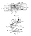
- FIG. 1a and 1b show a longitudinal section and a plan view of an embodiment of a synchronizing device according to the invention
- FIGs. 2, 3, 4a and 4b show end views of a synchronizer hub, an engaging sleeve, a first synchronizing ring and a second synchronizing ring, respectively, of the synchronizing device shown in Figs. 1a and 1b.
- the synchronizing device shown i Fig. 1a is based on a well known kind of synchronizing device and only components necessary for the understanding of the invention will be described here.
- the synchronizing device comprises a synchronizer hub 1 which is intended to be non-rotatably joined to a shaft (not shown) in a gearbox housing.
- An engaging sleeve 2 is non-rotatably but axially displaceably mounted on the synchronizer hub 1 by means of interengaging external teeth 3 on the hub 1 and two groups of different internal teeth 4a and 4b on the engaging sleeve 2, as will be described in more detail with reference to Fig. 1b, 2 and 3.
- a gear wheel 5a and 5b On either side of the hub 1 there is a gear wheel 5a and 5b, respectively, which is rotatably mounted on said shaft.
- a clutch disc 6a and 6b provided with external teeth 7 along the whole circumference is non-rotatably joined to each gear wheel 5a and 5b.
- a first and a second outer synchronizing ring 8a and 8b is non-rotatably but axially displaceably mounted on the synchronizer hub 1.
- the rings 8a and 8b have external blocker teeth 9a and 9b and internal conical friction surfaces 10a and 10b facing external conical friction surfaces 1 1a and 11b on intermediate ring elements 12a and 12b which are non-rotatably joined to each clutch disc 6a and 6b.
- An inner synchronizing ring 13 is non-rotatably joined to the synchronizing ring 8a radially inside the the intermediate ring element 12a.
- the synchronizing ring 8a, the intermediate ring element 12a and the inner synchronizer ring 13 are part of a multi (twin) ring system while the synchronizing ring 8b and the intermediate ring element 12b are part of a single ring system.
- a corresponding friction surface is machined in one piece with the gear wheel.
- the synchronizer hub 1 has three teeth 15 which are wider than the teeth 3 and spaced 120° from each other.
- the engaging sleeve 2 (Fig. 3) has corresponding grooves 16.
- the engaging sleeve 2 has two groups of different kinds of internal teeth 4a and 4b. Each group is divided into three alternating sets of teeth, each set extending 60° peripherally. The described features guarantee a predetermined position of the teeth on the engaging sleeve 2 in relation to the hub 1. Figs.
- 4a and 4b disclose the synchronizing rings 8a and 8b which have internal teeth 17 engaging external grooves 18 on the synchronizing hub 1 to locate each synchronizing ring in a predetermined position in relation to the engaging sleeve 2.
- the blocker teeth 9a and 9b on the synchronizing rings 8a and 8b, respectively, are grouped into three sets, each set extending 60° peripherally and separated by areas 19a and 19b lacking blocker teeth. As can be seen in Figs. 4a and 4b the blocker teeth 9a and the areas 19a on the synchronizing ring 8a are displaced 60° in relation to the blocker teeth 9b and the areas 19b on the synchronizing ring 8b.
- the teeth 4a and 4b on the engaging sleeve 2 and the blocker teeth 9a and 9b on the synchronizing rings 8a and 8b have V-shaped end surfaces 20a, 20b, 21a and 21b, respectively.
- the end surfaces 20a of the teeth 4a on the engaging sleeve 2 and the end surface 21a on the blocker teeth 9a of the left synchronizing ring 8a have a blocking angle ⁇ which is approximately 90°, while the end surfaces 20b of the teeth 4b on the engaging sleeve 2 and the end surfaces 21b on the blocker teeth of the right synchronizing ring 8b have a blocking angle ⁇ which is approximately 120°, thereby adapting the blocking angles to the friction torque differences between a single synchronizing ring synchronizer and a twin synchronizing ring synchronizer.
- a blocking angle ⁇ which is approximately 90°
- the end surfaces 20b of the teeth 4b on the engaging sleeve 2 and the end surfaces 21b on the blocker teeth of the right synchronizing ring 8b have a blocking angle ⁇ which is approximately 120°, thereby adapting the blocking angles to the friction torque differences between a single synchronizing ring synchronizer and a twin synchronizing ring synchronizer.
- the teeth 4a on the engaging sleeve 2 are longer in the direction of the axis of rotation than the teeth 4b, which means that the teeth 4a will hit the plane of rotation "a" of the tips of the teeth 7 on the clutch discs 6a and 6b before the teeth 4b.
- An advantage of this feature is that, after the synchronizing process is completed, final engagement of the engaging sleeve with the clutch discs 6a and 6b will start with the engagement of the engaging sleeve teeth 4a having the smaller angle with the clutch disc teeth 7 both when engaging the gear wheel 5a having the twin synchronizing system and the gear wheel 5b having the single synchronizing ring system.
- the torque indexing the engaging sleeve teeth 4a and 4b and the clutch disc teeth 7 will be the same in both cases.
- a synchronizing device having a common engaging sleeve for a multi ring synchronizing system, e. g. for a third gear, and a single ring synchronizing system, e.g. for a fourth gear on either side of a synchronizer hub.
- an engaging sleeve having the features described above could also be used for engaging opposite gear wheels having a common engaging sleeve, both of which have single synchronizing ring systems. If, for instance, in a gearbox the same engaging sleeve should be used for a fifth gear and reverse, a first group of teeth on the engaging sleeve having a small blocking angle together with a synchronizing ring with teeth with a small blocking angle could be used for reverse and a second group of teeth with larger teeth together with a synchronizing ring with larger teeth could be used for the fifth gear, since reverse is normally engaged when the vehicle is moving very slowly or not at all.
Landscapes
- Engineering & Computer Science (AREA)
- General Engineering & Computer Science (AREA)
- Mechanical Engineering (AREA)
- Mechanical Operated Clutches (AREA)
Abstract
Description
- The present invention relates to a synchronizing device in a motor vehicle gearbox, comprising a synchronizer hub, intended to be non-rotatably joined to a shaft in a gearbox, an engaging sleeve, which is non-rotatably but axially displaceably mounted on the synchronizer hub by means of interengaging external teeth on the synchronizer hub and internal teeth on the engaging sleeve, first and second clutch discs provided with external teeth and mounted on each side of the synchronizer hub, said discs being designed to be non-rotatably joined to a first and second gear wheel rotatably mounted on said shaft on each side of the synchronizer hub and being lockable relative to the synchronizer hub by axial displacement of the engaging sleeve from a neutral to an engaging position, in which the internal teeth on the engaging sleeve engage with the external teeth on the clutch discs, and first and second synchronizing rings mounted on each side of the synchronizer hub between the hub and the clutch discs, each synchronizing ring having external blocker teeth engaging with the internal teeth on the engaging sleeve and an internal conical friction surface engaging with an external friction surface on an element non-rotatably joined to each clutch disc when the engaging sleeve is displaced from the neutral position to an engaging position, the internal teeth on the engaging sleeve having opposite V-shaped end surfaces facing corresponding V-shaped surfaces on the synchronizing ring blocker teeth and the clutch disc teeth.
- When shifting gears in a gearbox of this kind the time it takes to complete the engagement process and the force that the driver has to apply on the gear shift lever largely depend on the size of the blocking angle of the teeth on the engaging sleeves and on the synchronizing rings. A large blocking angle requires a larger force on the gear shift lever and a longer synchronizing and engagement time. On the other hand one assures that the the synchronizing process is completed when the teeth of the engaging sleeve engage with the teeth of the clutch discs. A smaller blocking angle requires less force on the gear shift lever and a shorter time before the engaging sleeve engages the clutch discs but instead there is a risk that the synchronizing process has not been completed when the teeth of the engaging sleeve hit the the teeth of the clutch disc.
- Since the friction torque is larger in multi synchronizing ring synchronizer systems than in single ring synchronizer systems one can use synchronizing rings with a smaller blocking angle in multi (double or triple) ring systems than in single ring systems without risking that the synchronizing process has not been completed before the teeth of the engaging sleeve hit the teeth of the clutch discs. It is known in the art to use both single and multi ring synchronizer systems in a single gearbox. Usually multi ring synchronizer systems are used for the lower gears, e.g. first, second and third gears, which require larger synchronizing torque than the higher gears. Usually single ring systems are used for the higher gears.
- In order to optimize shift quality in such gearboxes the components of the multi ring synchronizer systems should have teeth with a smaller blocking angle than the single ring synchronizer systems. However, this requires the manufacture and the assembly of, among other things, at least two and in some cases even three, different engaging sleeves, one having teeth with a smaller blocking angle at both ends, one having teeth with a larger blocking angle at both ends and one having teeth with a smaller angle at one end and a larger angle at the opposite end. Of course this increases the cost compared with a gearbox having only one kind of engaging sleeve. There is also a risk for mixing the various engaging sleeves when assembling the gearboxes. In order to reduce costs and eliminate the risk for errors in the assembling process it is previously known to use engaging sleeves having the same blocking angle for single and multi ring synchronizer systems. In such cases a larger than necessary blocking angle has to be used for the multi ring synchronizer systems which means that shift quality will not be optimized for all gears.
- The purpose of the present invention is to achieve a synchronizing device of the type described by way of introduction, by means of which it possible to use one and the same engaging sleeve for synchronizing rings and clutch discs having teeth with different blocking angles.
- This is achieved according to the invention by virtue of the fact that the teeth on the engaging sleeve are divided into at least a first and a second group, the teeth of the first group having V-shaped end surfaces with a first blocking angle while the teeth of the second group have V-shaped end surfaces with a second blocking angle different from the first blocking angle, and that the first synchronizing ring has blocker teeth with a V-shaped end surface having said first blocking angle in areas facing said first teeth group on the engaging sleeve and lacks teeth in intermediate areas facing the second teeth group, while the second synchronizing ring has blocker teeth with a V-shaped end surface having said second blocking angle in areas facing said second teeth group and lacks blocker teeth in intermediate areas facing the first teeth group.
- The invention is based on the fact that it is not necessary that teeth along the whole circumference of the engaging sleeve and the synchronizing rings are effective to transmit torque during the synchronizing process. When teeth along the whole circumference of the engaging sleeve and the synchronizing ring are divided into two groups only half of the total amount of teeth are effective on each side.
- The invention will be described in more detail below with reference to the accompanying drawings, where Figs. 1a and 1b show a longitudinal section and a plan view of an embodiment of a synchronizing device according to the invention, Figs. 2, 3, 4a and 4b show end views of a synchronizer hub, an engaging sleeve, a first synchronizing ring and a second synchronizing ring, respectively, of the synchronizing device shown in Figs. 1a and 1b.
- The synchronizing device shown i Fig. 1a is based on a well known kind of synchronizing device and only components necessary for the understanding of the invention will be described here. The synchronizing device comprises a synchronizer hub 1 which is intended to be non-rotatably joined to a shaft (not shown) in a gearbox housing. An
engaging sleeve 2 is non-rotatably but axially displaceably mounted on the synchronizer hub 1 by means of interengagingexternal teeth 3 on the hub 1 and two groups of differentinternal teeth 4a and 4b on theengaging sleeve 2, as will be described in more detail with reference to Fig. 1b, 2 and 3. On either side of the hub 1 there is a gear wheel 5a and 5b, respectively, which is rotatably mounted on said shaft. A clutch disc 6a and 6b provided withexternal teeth 7 along the whole circumference is non-rotatably joined to each gear wheel 5a and 5b. A first and a second outer synchronizing ring 8a and 8b is non-rotatably but axially displaceably mounted on the synchronizer hub 1. The rings 8a and 8b haveexternal blocker teeth 9a and 9b and internal conical friction surfaces 10a and 10b facing external conical friction surfaces 1 1a and 11b onintermediate ring elements 12a and 12b which are non-rotatably joined to each clutch disc 6a and 6b. An inner synchronizing ring 13 is non-rotatably joined to the synchronizing ring 8a radially inside the theintermediate ring element 12a. Thus, the synchronizing ring 8a, theintermediate ring element 12a and the inner synchronizer ring 13 are part of a multi (twin) ring system while the synchronizing ring 8b and the intermediate ring element 12b are part of a single ring system. Usually in single ring systems instead of having a separate ring element 12b with anexternal friction surface 11b joined to the gear wheel, a corresponding friction surface is machined in one piece with the gear wheel. - As shown in Fig. 2 the synchronizer hub 1 has three
teeth 15 which are wider than theteeth 3 and spaced 120° from each other. The engaging sleeve 2 (Fig. 3) hascorresponding grooves 16. When mounting theengaging sleeve 2 on the synchronizer hub 1 the sleeve can only be mounted in an angular position in which theteeth 15 fit in thegrooves 16. As stated above theengaging sleeve 2 has two groups of different kinds ofinternal teeth 4a and 4b. Each group is divided into three alternating sets of teeth, each set extending 60° peripherally. The described features guarantee a predetermined position of the teeth on theengaging sleeve 2 in relation to the hub 1. Figs. 4a and 4b disclose the synchronizing rings 8a and 8b which haveinternal teeth 17 engaging external grooves 18 on the synchronizing hub 1 to locate each synchronizing ring in a predetermined position in relation to theengaging sleeve 2. Theblocker teeth 9a and 9b on the synchronizing rings 8a and 8b, respectively, are grouped into three sets, each set extending 60° peripherally and separated byareas 19a and 19b lacking blocker teeth. As can be seen in Figs. 4a and 4b theblocker teeth 9a and theareas 19a on the synchronizing ring 8a are displaced 60° in relation to the blocker teeth 9b and the areas 19b on the synchronizing ring 8b. - When the
engaging sleeve 2 is displaced to the left from the neutral position shown in Fig. 1a the teeth 4a on theengaging sleeve 2 will engage with theblocker teeth 9a on the outer synchronizing ring 8a. Theteeth 4b facing theareas 19a lacking blocker teeth will pass freely over the synchronizing ring when the synchronizing process is completed and the engaging sleeve is finally displaced to its left-hand end position in which theteeth 4a and 4b engage with theteeth 7 on the clutch disc 6a. Similarly, when theengaging sleeve 2 is displaced to the right from the neutral position theteeth 4b will engage with the blocker teeth 9b on the synchronizing ring 8b. The teeth 4a facing the areas 19b lacking blocker teeth will pass freely over the synchronizing ring 8b when the synchronizing process is completed and the engaging ring is finally displaced to its right hand end position in which theteeth 4a and 4b engage with the teeth on the clutch disc 6b. - As shown in Fig. 1b the
teeth 4a and 4b on theengaging sleeve 2 and theblocker teeth 9a and 9b on the synchronizing rings 8a and 8b have V-shaped end surfaces end surfaces 20a of the teeth 4a on theengaging sleeve 2 and theend surface 21a on theblocker teeth 9a of the left synchronizing ring 8a have a blocking angle α which is approximately 90°, while theend surfaces 20b of theteeth 4b on theengaging sleeve 2 and the end surfaces 21b on the blocker teeth of the right synchronizing ring 8b have a blocking angle β which is approximately 120°, thereby adapting the blocking angles to the friction torque differences between a single synchronizing ring synchronizer and a twin synchronizing ring synchronizer. As can be seen in Fig. 1b the teeth 4a on theengaging sleeve 2 are longer in the direction of the axis of rotation than theteeth 4b, which means that the teeth 4a will hit the plane of rotation "a" of the tips of theteeth 7 on the clutch discs 6a and 6b before theteeth 4b. An advantage of this feature is that, after the synchronizing process is completed, final engagement of the engaging sleeve with the clutch discs 6a and 6b will start with the engagement of the engaging sleeve teeth 4a having the smaller angle with theclutch disc teeth 7 both when engaging the gear wheel 5a having the twin synchronizing system and the gear wheel 5b having the single synchronizing ring system. Thus, the torque indexing theengaging sleeve teeth 4a and 4b and theclutch disc teeth 7 will be the same in both cases. - The invention has been described above with reference to an embodiment with a synchronizing device having a common engaging sleeve for a multi ring synchronizing system, e. g. for a third gear, and a single ring synchronizing system, e.g. for a fourth gear on either side of a synchronizer hub.
- Within the scope of the invention an engaging sleeve having the features described above could also be used for engaging opposite gear wheels having a common engaging sleeve, both of which have single synchronizing ring systems. If, for instance, in a gearbox the same engaging sleeve should be used for a fifth gear and reverse, a first group of teeth on the engaging sleeve having a small blocking angle together with a synchronizing ring with teeth with a small blocking angle could be used for reverse and a second group of teeth with larger teeth together with a synchronizing ring with larger teeth could be used for the fifth gear, since reverse is normally engaged when the vehicle is moving very slowly or not at all.
Claims (6)
- Synchronizing device in a motor vehicle gearbox comprising a synchronizer hub (1), intended to be non-rotatably joined to a shaft in a gearbox, an engaging sleeve (2), which is non-rotatably but axially displaceably mounted on the synchronizer hub by means of interengaging external teeth (3) on the synchronizer hub and internal teeth (4a,4b) on the engaging sleeve, first and second clutch discs (6a,6b) provided with external teeth and mounted on each side of the synchronizer hub, said discs being designed to be non-rotatably joined to a first and second gear (5a,5b) rotatably mounted on said shaft on each side of the synchronizer hub and being lockable relative to the synchronizer hub by axial displacement of the engaging sleeve from a neutral to an engaging position, in which the internal teeth on the engaging sleeve engage with the external teeth on the clutch discs, and first and second synchronizing rings (8a,8b) mounted on each side of the synchronizer hub between the hub and the clutch discs, each synchronizing ring having external blocker teeth (9a or 9b) engaging with the internal teeth on the engaging sleeve and an internal conical friction surface (10a,10b) engaging with an external friction surface (11a,11b) on an element (12a,12b) non-rotatably joined to each clutch disc when the engaging sleeve is displaced from the neutral position to an engaging position, the internal teeth on the engaging sleeve having opposite V-shaped end surfaces (20a,20b) facing corresponding V-shaped surfaces (21a,21b) on the synchronizing ring blocker teeth, characterized in that the teeth (4a,4b) on the engaging sleeve (2) are divided into at least a first and a second group, the teeth of the first group having V-shaped end surfaces (20a) with a first blocking angle (α) while the teeth (4b) of the second group has V-shaped end surfaces (20b) with a second blocking angle (β) different from the first blocking angle, and that the first synchronizing ring has blocker teeth (9a) with a V-shaped end surface having said first blocking angle (α) only in areas facing said first teeth group on the engaging sleeve and lacks teeth in intermediate areas (19a) facing the second teeth group while the second synchronizing ring (8b) has blocker teeth (9b) with a V-shaped end surface having said second blocking angle (β) in areas facing said second teeth group and lacks blocker teeth in intermediate areas (19b) facing the first teeth group.
- Synchronizing device according to claim 1, characterized in that the synchronizer hub (1) and the engaging sleeve (2) have co-operating guide heels (15) and guide grooves (16) locating the engaging sleeve in a predetermined angular position on the synchronizer hub.
- Synchronizing device according to claim 1, characterized in that the synchronizer hub (1) and the first and the second synchronizing rings (8a,8b), respectively, have co-operating guide grooves (18) and guide heels (17) locating the synchronizing rings in first and second predetermined angular positions, wherein the blocker teeth of the first and the second synchronizing rings are facing the first and the second group of teeth on the engaging sleeve, respectively.
- Synchronizing devise according to one of claims 1-3, characterized in that each group of teeth (4a,4b) on the engaging sleeve (2) is divided into at least three sets of teeth and that each set in one group adjoins a set in another group.
- Synchronizing devise according to one of claims 1-4, characterized in that at least a third synchronizing ring (13) is mounted concentric with and radially inside one (8a) of the first and second synchronizing rings, teeth (4a) on the engaging sleeve facing multiple synchronizing rings (8a,13) having a blocking angle (α), which is smaller than the blocking angle (β) of the teeth facing the single synchronizing ring (8b).
- Synchronizing device according to one of claims 1-5, characterized in that the internal teeth (4a) on the engaging ring (2) having the smaller blocking angle (α) have a larger axial extension than the internal teeth (4b) on the engaging ring having the larger blocking angle (β).
Priority Applications (3)
| Application Number | Priority Date | Filing Date | Title |
|---|---|---|---|
| EP01850193A EP1310692B1 (en) | 2001-11-09 | 2001-11-09 | Synchronizing device in a motor vehicle gearbox |
| DE60106462T DE60106462T2 (en) | 2001-11-09 | 2001-11-09 | Synchronization device in a vehicle transmission |
| US10/065,177 US6719111B2 (en) | 2001-11-09 | 2002-09-24 | Synchronizing device in a motor vehicle gearbox |
Applications Claiming Priority (1)
| Application Number | Priority Date | Filing Date | Title |
|---|---|---|---|
| EP01850193A EP1310692B1 (en) | 2001-11-09 | 2001-11-09 | Synchronizing device in a motor vehicle gearbox |
Publications (2)
| Publication Number | Publication Date |
|---|---|
| EP1310692A1 true EP1310692A1 (en) | 2003-05-14 |
| EP1310692B1 EP1310692B1 (en) | 2004-10-13 |
Family
ID=8184897
Family Applications (1)
| Application Number | Title | Priority Date | Filing Date |
|---|---|---|---|
| EP01850193A Expired - Lifetime EP1310692B1 (en) | 2001-11-09 | 2001-11-09 | Synchronizing device in a motor vehicle gearbox |
Country Status (3)
| Country | Link |
|---|---|
| US (1) | US6719111B2 (en) |
| EP (1) | EP1310692B1 (en) |
| DE (1) | DE60106462T2 (en) |
Cited By (3)
| Publication number | Priority date | Publication date | Assignee | Title |
|---|---|---|---|---|
| EP2372182A1 (en) * | 2010-02-26 | 2011-10-05 | Schaeffler Technologies AG & Co. KG | Construction unit for transferring torque |
| EP2314894A3 (en) * | 2009-10-23 | 2014-01-29 | Schaeffler Technologies AG & Co. KG | Synchronising device |
| CN114183506A (en) * | 2020-09-15 | 2022-03-15 | 郑州宇通客车股份有限公司 | A vehicle transmission, a vehicle power system and a vehicle |
Families Citing this family (6)
| Publication number | Priority date | Publication date | Assignee | Title |
|---|---|---|---|---|
| JP2007239952A (en) * | 2006-03-10 | 2007-09-20 | Aisin Ai Co Ltd | Synchronizer ring |
| US9604109B2 (en) * | 2008-03-28 | 2017-03-28 | John Travis Gaffney | Golf club head cover |
| WO2010014100A1 (en) * | 2008-07-31 | 2010-02-04 | Wagner Jeremy J | Transmission gear engagement mechanism and method of operation |
| GB2468355B (en) * | 2009-03-06 | 2013-09-11 | Gm Global Tech Operations Inc | Double-acting synchronizer |
| US8221282B2 (en) * | 2009-12-08 | 2012-07-17 | GM Global Technology Operations LLC | Synchronizer in electro-mechanical transmission |
| DE102010010402A1 (en) * | 2010-03-05 | 2011-09-08 | GM Global Technology Operations LLC , (n. d. Ges. d. Staates Delaware) | clutch |
Citations (3)
| Publication number | Priority date | Publication date | Assignee | Title |
|---|---|---|---|---|
| EP0515243A1 (en) * | 1991-05-24 | 1992-11-25 | Regie Nationale Des Usines Renault S.A. | Synchronizer for gearbox |
| DE4224271A1 (en) * | 1992-07-23 | 1994-01-27 | Getrag Getriebe Zahnrad | Synchromesh device for vehicle gearbox - has extensions on meshing tooth tips of coupling and switching sleeve |
| EP0994267A1 (en) * | 1998-10-13 | 2000-04-19 | HOERBIGER Antriebstechnik GmbH | Blocking-synchroniser ring for synchronised speed-changing transmission |
Family Cites Families (6)
| Publication number | Priority date | Publication date | Assignee | Title |
|---|---|---|---|---|
| DE2659448C2 (en) * | 1976-12-30 | 1981-11-26 | Getrag Getriebe- Und Zahnradfabrik Gmbh, 7140 Ludwigsburg | Synchronizing device for clutches, especially of gearboxes |
| DE3444670C1 (en) * | 1984-12-07 | 1986-07-17 | Getrag Getriebe- Und Zahnradfabrik Gmbh, 7140 Ludwigsburg | Synchronizer for clutches |
| DE3622464C1 (en) * | 1986-07-04 | 1987-12-17 | Getrag Getriebe- Und Zahnradfabrik Gmbh, 7140 Ludwigsburg, De | |
| DE3728903C1 (en) * | 1987-08-29 | 1988-11-24 | Daimler Benz Ag | Coupling teeth of a lock-synchronized clutch, in particular a gear change transmission with gear wheels that can be switched off from its shaft |
| US5135087A (en) * | 1991-01-16 | 1992-08-04 | New Venture Gear, Inc. | Dual-cone synchronizer with servo action |
| DE10103423A1 (en) * | 2001-01-26 | 2002-08-01 | Zahnradfabrik Friedrichshafen | Synchronizing device with asymmetrical teeth |
-
2001
- 2001-11-09 DE DE60106462T patent/DE60106462T2/en not_active Expired - Lifetime
- 2001-11-09 EP EP01850193A patent/EP1310692B1/en not_active Expired - Lifetime
-
2002
- 2002-09-24 US US10/065,177 patent/US6719111B2/en not_active Expired - Fee Related
Patent Citations (3)
| Publication number | Priority date | Publication date | Assignee | Title |
|---|---|---|---|---|
| EP0515243A1 (en) * | 1991-05-24 | 1992-11-25 | Regie Nationale Des Usines Renault S.A. | Synchronizer for gearbox |
| DE4224271A1 (en) * | 1992-07-23 | 1994-01-27 | Getrag Getriebe Zahnrad | Synchromesh device for vehicle gearbox - has extensions on meshing tooth tips of coupling and switching sleeve |
| EP0994267A1 (en) * | 1998-10-13 | 2000-04-19 | HOERBIGER Antriebstechnik GmbH | Blocking-synchroniser ring for synchronised speed-changing transmission |
Cited By (4)
| Publication number | Priority date | Publication date | Assignee | Title |
|---|---|---|---|---|
| EP2314894A3 (en) * | 2009-10-23 | 2014-01-29 | Schaeffler Technologies AG & Co. KG | Synchronising device |
| EP2372182A1 (en) * | 2010-02-26 | 2011-10-05 | Schaeffler Technologies AG & Co. KG | Construction unit for transferring torque |
| CN114183506A (en) * | 2020-09-15 | 2022-03-15 | 郑州宇通客车股份有限公司 | A vehicle transmission, a vehicle power system and a vehicle |
| CN114183506B (en) * | 2020-09-15 | 2023-05-09 | 宇通客车股份有限公司 | Vehicle transmission, vehicle power system and vehicle |
Also Published As
| Publication number | Publication date |
|---|---|
| US20030089571A1 (en) | 2003-05-15 |
| EP1310692B1 (en) | 2004-10-13 |
| DE60106462T2 (en) | 2005-11-03 |
| DE60106462D1 (en) | 2004-11-18 |
| US6719111B2 (en) | 2004-04-13 |
Similar Documents
| Publication | Publication Date | Title |
|---|---|---|
| EP0652385B1 (en) | Synchronizer clutch assembly for multiple ratio gearing | |
| EP0756098B1 (en) | Synchronizer clutch assembly | |
| US5638930A (en) | Strut-type synchronizer | |
| US9010512B2 (en) | Dog clutch for automated transmission | |
| US9964160B2 (en) | Actuator mechanism for transfer case | |
| US20120006643A1 (en) | Double-acting synchronizer | |
| EP1310692B1 (en) | Synchronizing device in a motor vehicle gearbox | |
| US10935082B2 (en) | Synchronizer device for a manual transmission | |
| US6554735B2 (en) | Planetary gear type differential apparatus | |
| KR100913829B1 (en) | Assembly system for the synchronization unit in the gearbox | |
| JPH02236040A (en) | Compond synchronizer having integrated axial lock means | |
| CN102619960B (en) | Transmission synchronizer assembly | |
| US20120048045A1 (en) | Transmission with reverse gear brake | |
| EP0390368B1 (en) | Improved transmission mainshaft gear retainer | |
| US5370590A (en) | Securing means for a planetary gear unit | |
| JP3016182B2 (en) | Multiple disc friction clutch | |
| GB2161870A (en) | Synchronous clutch mechanism | |
| CN117441068A (en) | Transmission with one shaft | |
| US5758753A (en) | Modular synchronizer assembly | |
| EP1038116B1 (en) | Synchronizing device in a vehicle gearbox | |
| JPH10141450A (en) | Transmission and thrust washer thereof | |
| EP1992831B1 (en) | Synchronizing unit for a gearbox of a motor vehicle | |
| CN104847881A (en) | Shift assembly of shift transmission of motor vehicle | |
| CZ129793A3 (en) | Gearbox | |
| EP3591247A1 (en) | Synchronizer for a mechanical transmission, particularly for a transmission of a vehicle |
Legal Events
| Date | Code | Title | Description |
|---|---|---|---|
| PUAI | Public reference made under article 153(3) epc to a published international application that has entered the european phase |
Free format text: ORIGINAL CODE: 0009012 |
|
| AK | Designated contracting states |
Designated state(s): AT BE CH CY DE DK ES FI FR GB GR IE IT LI LU MC NL PT SE TR |
|
| AX | Request for extension of the european patent |
Extension state: AL LT LV MK RO SI |
|
| 17P | Request for examination filed |
Effective date: 20031024 |
|
| AKX | Designation fees paid |
Designated state(s): DE GB SE |
|
| GRAP | Despatch of communication of intention to grant a patent |
Free format text: ORIGINAL CODE: EPIDOSNIGR1 |
|
| GRAS | Grant fee paid |
Free format text: ORIGINAL CODE: EPIDOSNIGR3 |
|
| GRAA | (expected) grant |
Free format text: ORIGINAL CODE: 0009210 |
|
| RAP1 | Party data changed (applicant data changed or rights of an application transferred) |
Owner name: FORD GLOBAL TECHNOLOGIES, LLC |
|
| AK | Designated contracting states |
Kind code of ref document: B1 Designated state(s): DE GB SE |
|
| REG | Reference to a national code |
Ref country code: GB Ref legal event code: FG4D |
|
| RIN1 | Information on inventor provided before grant (corrected) |
Inventor name: BENGTSSON, LARS Inventor name: TORSEIN, RICHARD Inventor name: WITTKE, PETER, DR. |
|
| REG | Reference to a national code |
Ref country code: IE Ref legal event code: FG4D |
|
| REF | Corresponds to: |
Ref document number: 60106462 Country of ref document: DE Date of ref document: 20041118 Kind code of ref document: P |
|
| REG | Reference to a national code |
Ref country code: SE Ref legal event code: TRGR |
|
| PLBE | No opposition filed within time limit |
Free format text: ORIGINAL CODE: 0009261 |
|
| STAA | Information on the status of an ep patent application or granted ep patent |
Free format text: STATUS: NO OPPOSITION FILED WITHIN TIME LIMIT |
|
| 26N | No opposition filed |
Effective date: 20050714 |
|
| PGFP | Annual fee paid to national office [announced via postgrant information from national office to epo] |
Ref country code: SE Payment date: 20141126 Year of fee payment: 14 Ref country code: GB Payment date: 20141119 Year of fee payment: 14 Ref country code: DE Payment date: 20141117 Year of fee payment: 14 |
|
| REG | Reference to a national code |
Ref country code: DE Ref legal event code: R119 Ref document number: 60106462 Country of ref document: DE |
|
| GBPC | Gb: european patent ceased through non-payment of renewal fee |
Effective date: 20151109 |
|
| PG25 | Lapsed in a contracting state [announced via postgrant information from national office to epo] |
Ref country code: SE Free format text: LAPSE BECAUSE OF NON-PAYMENT OF DUE FEES Effective date: 20151110 |
|
| PG25 | Lapsed in a contracting state [announced via postgrant information from national office to epo] |
Ref country code: DE Free format text: LAPSE BECAUSE OF NON-PAYMENT OF DUE FEES Effective date: 20160601 Ref country code: GB Free format text: LAPSE BECAUSE OF NON-PAYMENT OF DUE FEES Effective date: 20151109 |