EP1310691A1 - Universal joint - Google Patents
Universal joint Download PDFInfo
- Publication number
- EP1310691A1 EP1310691A1 EP01126718A EP01126718A EP1310691A1 EP 1310691 A1 EP1310691 A1 EP 1310691A1 EP 01126718 A EP01126718 A EP 01126718A EP 01126718 A EP01126718 A EP 01126718A EP 1310691 A1 EP1310691 A1 EP 1310691A1
- Authority
- EP
- European Patent Office
- Prior art keywords
- joint
- pipe
- spring pin
- shaft
- yoke
- Prior art date
- Legal status (The legal status is an assumption and is not a legal conclusion. Google has not performed a legal analysis and makes no representation as to the accuracy of the status listed.)
- Granted
Links
- 238000009434 installation Methods 0.000 claims description 38
- 230000002708 enhancing effect Effects 0.000 claims description 2
- 230000003247 decreasing effect Effects 0.000 description 7
- 238000004519 manufacturing process Methods 0.000 description 4
- 238000000034 method Methods 0.000 description 4
- 239000007769 metal material Substances 0.000 description 3
- 239000000463 material Substances 0.000 description 2
- 241000239290 Araneae Species 0.000 description 1
- 239000000428 dust Substances 0.000 description 1
- 238000003780 insertion Methods 0.000 description 1
- 230000037431 insertion Effects 0.000 description 1
- 238000012986 modification Methods 0.000 description 1
- 230000004048 modification Effects 0.000 description 1
- 238000005096 rolling process Methods 0.000 description 1
- 239000000126 substance Substances 0.000 description 1
Images




Classifications
-
- F—MECHANICAL ENGINEERING; LIGHTING; HEATING; WEAPONS; BLASTING
- F16—ENGINEERING ELEMENTS AND UNITS; GENERAL MEASURES FOR PRODUCING AND MAINTAINING EFFECTIVE FUNCTIONING OF MACHINES OR INSTALLATIONS; THERMAL INSULATION IN GENERAL
- F16D—COUPLINGS FOR TRANSMITTING ROTATION; CLUTCHES; BRAKES
- F16D3/00—Yielding couplings, i.e. with means permitting movement between the connected parts during the drive
- F16D3/02—Yielding couplings, i.e. with means permitting movement between the connected parts during the drive adapted to specific functions
- F16D3/06—Yielding couplings, i.e. with means permitting movement between the connected parts during the drive adapted to specific functions specially adapted to allow axial displacement
-
- F—MECHANICAL ENGINEERING; LIGHTING; HEATING; WEAPONS; BLASTING
- F16—ENGINEERING ELEMENTS AND UNITS; GENERAL MEASURES FOR PRODUCING AND MAINTAINING EFFECTIVE FUNCTIONING OF MACHINES OR INSTALLATIONS; THERMAL INSULATION IN GENERAL
- F16C—SHAFTS; FLEXIBLE SHAFTS; ELEMENTS OR CRANKSHAFT MECHANISMS; ROTARY BODIES OTHER THAN GEARING ELEMENTS; BEARINGS
- F16C29/00—Bearings for parts moving only linearly
- F16C29/12—Arrangements for adjusting play
- F16C29/123—Arrangements for adjusting play using elastic means
-
- F—MECHANICAL ENGINEERING; LIGHTING; HEATING; WEAPONS; BLASTING
- F16—ENGINEERING ELEMENTS AND UNITS; GENERAL MEASURES FOR PRODUCING AND MAINTAINING EFFECTIVE FUNCTIONING OF MACHINES OR INSTALLATIONS; THERMAL INSULATION IN GENERAL
- F16C—SHAFTS; FLEXIBLE SHAFTS; ELEMENTS OR CRANKSHAFT MECHANISMS; ROTARY BODIES OTHER THAN GEARING ELEMENTS; BEARINGS
- F16C3/00—Shafts; Axles; Cranks; Eccentrics
- F16C3/02—Shafts; Axles
- F16C3/03—Shafts; Axles telescopic
-
- F—MECHANICAL ENGINEERING; LIGHTING; HEATING; WEAPONS; BLASTING
- F16—ENGINEERING ELEMENTS AND UNITS; GENERAL MEASURES FOR PRODUCING AND MAINTAINING EFFECTIVE FUNCTIONING OF MACHINES OR INSTALLATIONS; THERMAL INSULATION IN GENERAL
- F16D—COUPLINGS FOR TRANSMITTING ROTATION; CLUTCHES; BRAKES
- F16D1/00—Couplings for rigidly connecting two coaxial shafts or other movable machine elements
- F16D1/10—Quick-acting couplings in which the parts are connected by simply bringing them together axially
-
- F—MECHANICAL ENGINEERING; LIGHTING; HEATING; WEAPONS; BLASTING
- F16—ENGINEERING ELEMENTS AND UNITS; GENERAL MEASURES FOR PRODUCING AND MAINTAINING EFFECTIVE FUNCTIONING OF MACHINES OR INSTALLATIONS; THERMAL INSULATION IN GENERAL
- F16D—COUPLINGS FOR TRANSMITTING ROTATION; CLUTCHES; BRAKES
- F16D3/00—Yielding couplings, i.e. with means permitting movement between the connected parts during the drive
- F16D3/16—Universal joints in which flexibility is produced by means of pivots or sliding or rolling connecting parts
- F16D3/26—Hooke's joints or other joints with an equivalent intermediate member to which each coupling part is pivotally or slidably connected
- F16D3/38—Hooke's joints or other joints with an equivalent intermediate member to which each coupling part is pivotally or slidably connected with a single intermediate member with trunnions or bearings arranged on two axes perpendicular to one another
- F16D3/382—Hooke's joints or other joints with an equivalent intermediate member to which each coupling part is pivotally or slidably connected with a single intermediate member with trunnions or bearings arranged on two axes perpendicular to one another constructional details of other than the intermediate member
- F16D3/387—Fork construction; Mounting of fork on shaft; Adapting shaft for mounting of fork
-
- F—MECHANICAL ENGINEERING; LIGHTING; HEATING; WEAPONS; BLASTING
- F16—ENGINEERING ELEMENTS AND UNITS; GENERAL MEASURES FOR PRODUCING AND MAINTAINING EFFECTIVE FUNCTIONING OF MACHINES OR INSTALLATIONS; THERMAL INSULATION IN GENERAL
- F16F—SPRINGS; SHOCK-ABSORBERS; MEANS FOR DAMPING VIBRATION
- F16F15/00—Suppression of vibrations in systems; Means or arrangements for avoiding or reducing out-of-balance forces, e.g. due to motion
- F16F15/10—Suppression of vibrations in rotating systems by making use of members moving with the system
-
- F—MECHANICAL ENGINEERING; LIGHTING; HEATING; WEAPONS; BLASTING
- F16—ENGINEERING ELEMENTS AND UNITS; GENERAL MEASURES FOR PRODUCING AND MAINTAINING EFFECTIVE FUNCTIONING OF MACHINES OR INSTALLATIONS; THERMAL INSULATION IN GENERAL
- F16D—COUPLINGS FOR TRANSMITTING ROTATION; CLUTCHES; BRAKES
- F16D1/00—Couplings for rigidly connecting two coaxial shafts or other movable machine elements
- F16D1/10—Quick-acting couplings in which the parts are connected by simply bringing them together axially
- F16D2001/103—Quick-acting couplings in which the parts are connected by simply bringing them together axially the torque is transmitted via splined connections
-
- Y—GENERAL TAGGING OF NEW TECHNOLOGICAL DEVELOPMENTS; GENERAL TAGGING OF CROSS-SECTIONAL TECHNOLOGIES SPANNING OVER SEVERAL SECTIONS OF THE IPC; TECHNICAL SUBJECTS COVERED BY FORMER USPC CROSS-REFERENCE ART COLLECTIONS [XRACs] AND DIGESTS
- Y10—TECHNICAL SUBJECTS COVERED BY FORMER USPC
- Y10T—TECHNICAL SUBJECTS COVERED BY FORMER US CLASSIFICATION
- Y10T403/00—Joints and connections
- Y10T403/32—Articulated members
- Y10T403/32254—Lockable at fixed position
- Y10T403/32467—Telescoping members
-
- Y—GENERAL TAGGING OF NEW TECHNOLOGICAL DEVELOPMENTS; GENERAL TAGGING OF CROSS-SECTIONAL TECHNOLOGIES SPANNING OVER SEVERAL SECTIONS OF THE IPC; TECHNICAL SUBJECTS COVERED BY FORMER USPC CROSS-REFERENCE ART COLLECTIONS [XRACs] AND DIGESTS
- Y10—TECHNICAL SUBJECTS COVERED BY FORMER USPC
- Y10T—TECHNICAL SUBJECTS COVERED BY FORMER US CLASSIFICATION
- Y10T403/00—Joints and connections
- Y10T403/70—Interfitted members
- Y10T403/7026—Longitudinally splined or fluted rod
Definitions
- the present invention relates to a universal joint, and in particular to an improved universal joint which is capable of providing an improved shaft connection for implementing a margin compensation, vibration decrease and a strength with respect to a temperature and rotational force between a pipe and shaft of a slip joint and between a slip joint and a yoke joint.
- a universal joint is installed at a slanted angle by a certain degree for thereby transferring a rotational force.
- the universal joint is formed of a yoke joint installed at a side for transferring a rotational force and at a side for receiving the same, and a slip joint which slips in an axial direction between the yoke joint.
- Figure 1 is a view illustrating a conventional universal joint. As shown therein, the yoke joint 1 is arranged in such a manner that two yokes are alternately engaged for thereby installing a pin in a radial direction at one end of the same.
- a cross shaped spider is installed therebetween for thereby transferring a rotational force from one side yoke to another side yoke in a state that the universal joint is slanted at a certain angle.
- the slip joint 2 is constituted in such a manner that a rotational force transferred from one side yoke joint 1 to the other side yoke joint 1 and the slip joint 2 slips in an axial direction.
- the slip joint 2 includes a pipe 3 connected with one side yoke joint 1 and a shaft 4 connected with the other side yoke joint 1.
- a pair of engaged serrations(or splines) 3a and 3b are formed in the inner side of the pipe 3 and the outer side of the shaft 4.
- a slip 3b is formed at an opened front end portion of the pipe 3 in an axial direction.
- a dust cap 6 is installed at an opened front end portion of the pipe 3 for preventing a foreign substance from being inserted into the pipe 3.
- a clip 5 is installed in an outer side of the slip 3b for preventing the pipe 3 and the shaft 4 from being loosened and limiting an axial movement of the pipe 3 and the shaft 4.
- a weight of 8 ⁇ 15kgf is applied in an axial direction of the pipe 3 and the shaft 4 in order to adjust the length of the slip joint 2.
- the above weight is not formed by a hand of a human.
- the slip joint 2 is installed into an interior of the yoke joint 1. As shown in Figure 3, an anti-vibration rubber 7 is installed between the slip joint 2 and the yoke joint 1.
- an anti-vibration rubber 7 formed of a rubber material having a good elastic force is installed between the inner portion of the yoke joint 1 and the outer portion of the slip joint 2 for thereby decreasing a vibration applied therebetween.
- a hole is formed in the slip joint 2, the yoke joint 1 and the anti-vibration rubber 7, respectively, in a radial direction, so that the slip joint 2, the yoke joint 1 and the anti-vibration rubber communicate each other.
- a pin-shaped stopper 8 is inserted into the interior of the hole for thereby stably supporting the slip joint 2, the yoke joint 1 and the anti-vibration rubber 7 in an axial direction and rotational direction.
- the anti-vibration rubber installed between the slip joint and the yoke joint may be degraded at a high and low temperature, and a crack may occur therein.
- the strength of the same is largely varied due to a high temperature.
- a universal joint which includes a slip joint in which a shaft is inserted into an interior of a hollow pipe for thereby implementing a rotation force transferring and slipping operation, a hollow yoke joint installed at both sides of the slip joint and having one side which surrounds the pipe and shaft, and an elastic means inserted between the pipe and shaft and both ends of the slip joint and the yoke joint for generating an elastic force in a radial direction.
- Figure 4 is a cross-sectional view illustrating a universal joint according to the present invention. As shown therein, the universal joint is formed of a longitudinal slip joint 20 and a yoke joint 10 installed at both ends of the slip joint 20.
- the yoke joint 10 is formed of two yokes for transferring a rotational force in an angled state at below a certain angle.
- the slip joint 20 installed between the yoke joint 10 transfers a rotational force and includes a pipe which transfers a rotational force and slips in an axial direction and a shaft 40 inserted therein.
- an elastic member and a transfer member are installed between the pipe 30 and the shaft 40 of the slip joint and the slip joint 20 and the yoke joint 10.
- the elastic member installed between the pipe30 and the shaft 40 of the slip joint 20 is formed of a hollow spring pin 150 having a cut-away side formed by rolling a metallic material in such a manner that it is extendable to the outside.
- the spring pin 150 is installed in such a manner that the distance of spaced-apart both ends is decreased, so that the spring pin 150 is retracted in the direction of the center side. After the installation, an elastic force is generated from the outer side.
- the spring pin 150 is closely installed between an inner surface of the pipe 30 and an outer surface of the shaft 40 for thereby transferring a rotational force therebetween.
- Three spring pins 150 are installed in each corresponding portions.
- a transfer member installed between the pipe 30 and the shaft 40 of the slip joint 20 for transferring a rotational force is provided for transferring a larger rotational force.
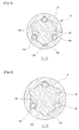
- a pair of installation grooves 110 and 120 formed in a circular shape opposite to the inner surface of the pipe 30 and the outer surface of the shaft 40 for inserting the spring pin 150 thereinto are formed in three portions, respectively.
- the diameter of the installation grooves 110 and 120 closely contacts with the outer diameter of the spring pin 150 when the outer diameter of the spring pin 150 is decreased and assembled.
- the transfer member includes an engaging protrusion 140 protruded from an outer surface of the shaft 40, and an engaging groove 130 formed in the interior of the oipe 30 for thereby receiving the engaging protrusion 140 thereinto.
- three installation grooves 10 and the engaging protrusions 140 are installed in the outer portion of the shaft 40 at the same angle.
- the installation groove 110 and the engaging groove 130 are formed in the interior of the pipe 30 to correspond thereto.
- the shapes of the installation grooves 110 and 120 and the engaging groove 130 are same, and the engaging protrusion 140 is protruded in the same shape as the spring pin 150.
- the engaging t protrusion 140 and the spring pin 150 are selectively inserted into the installation grooves 110 and 120 and the engaging groove 130.
- the elastic member and the transfer member are implemented between the slip joint 20 and the yoke joint 10 in the similar manner.
- the elastic member between the slip joint 20 and the yoke joint is implemented based on the spring pin 150 which are installed in corresponding portions by three.
- the transfer member between the slip joint 20 and the yoke joint 10 is implemented based on a pair of the installation grooves 160 and 170 which are formed in three portions in the outer surface of the pipe 30 and the inner surface of the yoke joint 10 to be opposite each other, so that the spring pins 150 are inserted thereinto.
- the transfer member between the slip joint 20 and the yoke joint 10 is formed of an engaging protrusion 190 protruded on the outer surface of the pipe 30 and an engaging groove 180 formed in the interior of the yoke joint 10, so that the engaging protrusion 190 is inserted thereinto.
- Three installation grooves 170 and engaging protrusions 190 are formed in the outer portion of the pipe 30 at the same angle, respectively, and the installation groove 160 and the engaging groove 180 are formed in the interior of the yoke joint to correspond with the same.
- one spring pin 150 is inserted into the interior of the installation grooves 110, 120, 160 and 170, respectively, and a metallic fixing pin 200 is inserted into the remaining grooves.
- the numbers of the spring pin 150 and the fixing pins 200 may be adjusted.
- Figure 9 is a disassembled perspective view illustrating another embodiment of the present invention. As shown therein, since the elements except for the elastic member and the transfer member are the same as the earlier embodiment of the present invention, the same element names and same reference numerals are used for the same elements.
- an elastic member installed between the pipe 30 and shaft 40 of the slip joint is formed of spring pins 350 which are opposite each other and are distanced from each other.
- the spring pin 350 is hollow and is formed in such a manner that a metal material is rolled in a pipe shape and an outer part of the same is cut-away, and a cross section in a radial direction is elongated and is tightly contacted between the pipe 30 and the shaft 40.
- the spring pin 350 includes a flat cross section formed in a radial direction so that the spring pin 350 does not roll and is installed in a compressed state in the direction of a center portion in such a manner that the distance of outer portions is decreased.
- the transfer member between the pipe 30 and the shaft 40 of the slip joint 20 is engaged in a certain direction so that the pipe 30 and the shaft 40 are more tightly engaged in the rotation direction and includes a pair of the opposite installation grooves 310 and 320 in the outer surface of the shaft 40 and the inner surface of the pipe 30, respectively.
- the installation grooves 310 and 320 are concaved in a shape that a half of the elongated hole is divided to correspond with an outer shape of the spring pin 350.
- the spring pin 350 is installed in a compressed state.
- the transfer member installed between the pipe 30 and the shaft 40 of the slip joint 20 includes an engaging protrusion 340 protruded from an outer surface of the shaft 40 and an engaging groove 330 concaved in an outer side in the inner portion of the pipe 30.
- Two engaging protrusions 340 are formed in the outer portion of the shaft 40 in a direction crossed with respect to two installation grooves 320.
- the installation groove and engaging groove 330 are formed in the inner portion of the pipe 30.
- the shapes of the installation grooves 310 and 320 and the engaging groove 330 are same, and the engaging protrusion 340 has a shape similar with the outer shape of the spring pin 350 for a selective insertion into the installation grooves 310 and 320 and the engaging groove 330.
- the elastic member and transfer member are adapted between the slip joint 20 and the yoke joint 10 in a similar manner.
- an elastic member installed between the slip joint 20 and the yoke joint 10 is installed at both opposite sides and includes a spring pin 350 having an elongated cross section in a radial direction.
- a transfer member between the slip joint 20 and the yoke joint 10 includes a pair of installation grooves 360 and 370 having elongated opposite cross sections in an outer surface of the shaft 40 and an inner surface of the pipe 30 in such a manner that the spring pin 350 is inserted.
- a transfer member installed between the slip joint 20 and the yoke joint 10 includes an engaging protrusion 390 protruded from an outer surface of the pipe 30 and an engaging grove 380 concaved in an inner portion of the yoke joint 10 to correspond with the engaging protrusion 390.
- two engaging protrusions 390 are formed in an outer portion of the pipe 30 in a direction crossed with two installation grooves 370.
- An installation groove 360 and an engaging groove 380 are formed in the inner potion of the yoke joint 10 to correspond with the engaging protrusions 390.
- the installation grooves 360 and 370 and the engaging groove 380 have the same shapes, and the engaging protrusion 390 has a shape similar with the outer shape of the spring pin 350 so that the engaging protrusion 390 is selectively inserted into the installation grooves 360 and 370 and the engaging groove 380.
- the engaging protrusions 140, 190 and 340, 390 of the engaging grooves 130, 180 and 330, 380 are inserted in an axial direction, and the shaft 40 and pipe 30 of the slip joint 20 and the slip joint 20 and the yoke joint 10 are fixed in the rotation direction.
- the engaging protrusions 140, 190 and 340, 390 are selectively installed into the engaging grooves 130, 180 and 330, 380 and the installation grooves 110, 120, 160, 170 and 310, 320, 360, 370
- the engaging grooves 130, 180 and 330, 380 and the installation grooves 110, 120, 160, 170 and 310, 320, 360, 370 into which the engaging protrusions 140, 190 and 340, 390 are not inserted have certain spaces so that the spring pins 150 and 350 are inserted into the opposite installation grooves 110, 120, 160, 170 and 310, 320, 360, 370.
- the spring pins 150 and 350 are retracted and inserted into the opposite engaging grooves 130, 180 and 330, 380 through the installation groves 110, 120, 160, 170 and 310, 320, 360, 370 and the opposite installation grooves 110, 120, 160, 170 and 310, 320, 360, 370 in the radial direction.
- the spring pins 150 and 350 generate an elastic force in an outer direction and is closely contacted between the shaft 40 and pipe 30 of the slip joint 20 and the slip joint 20 and the yoke joint 10 and are fixed in the rotation direction and axial direction, respectively.
- the universal joint according to the present invention includes an elastic member formed of a spring pin and a pin between the pipe and shaft of the slip joint and between the slip joint and the yoke joint, and a transfer member formed of an installation groove, an engaging protrusion and an engaging grove.
- the slipping operation of the slip joint is easily implemented by the spring pin and pin between the pipe and shaft, and when the length of the slip joint is varied, the noise and vibration are decreased, and a reliability of the product is enhanced.
- the margin in the rotation direction is compensated between the pipe and shaft of the slip joint and the slip joint and yoke joint.
- a noise due to a margin therebetween is decreased, and an efficient rotation force transferring operation implemented.
- a spring pin is formed of a metallic material between the slip joint and the yoke joint, the strengths against a high and low temperature and for transferring a rotational force are enhanced.
- the engaging groove and engaging protrusion are integrally formed in the inner and outer sides of the slip joint and yoke joint, an additional part and an additional process may be removed for assembling the slip joint and the yoke joint.
Landscapes
- Engineering & Computer Science (AREA)
- General Engineering & Computer Science (AREA)
- Mechanical Engineering (AREA)
- Ocean & Marine Engineering (AREA)
- Physics & Mathematics (AREA)
- Acoustics & Sound (AREA)
- Aviation & Aerospace Engineering (AREA)
- Snaps, Bayonet Connections, Set Pins, And Snap Rings (AREA)
- Shafts, Cranks, Connecting Bars, And Related Bearings (AREA)
Abstract
Description
Claims (10)
- A universal joint, comprising:a slip joint in which a shaft is inserted into an interior of a hollow pipe for thereby implementing a rotation force transferring and slipping operation;a hollow yoke joint installed at both sides of the slip joint and having one side which surrounds the pipe and shaft; andan elastic means inserted between the pipe and shaft and both ends of the slip joint and the yoke joint for generating an elastic force in a radial direction.
- The joint of claim 1, wherein a transfer means is installed between the pipe and shaft and both ends of the slip joint and the yoke joint and is integrally formed with the pipe and shaft and the slip joint and the yoke joint for thereby enhancing a rotational and transferring force.
- The joint of claim 1, wherein said elastic means is formed of a spring pin in which a hollow outer portion is cut-away in an axial direction and is compressed in a direction of a center portion for thereby generating an elastic force in an outer direction.
- The joint of claim 2, wherein said transfer means is formed of an installation groove formed in an inner portion of the pipe and an outer portion of the shaft and an inner portion of the yoke joint and an outer portion of the pipe, respectively, which are opposite to each other in a radial direction so that the spring pin is retracted and inserted.
- The joint of claim 2, wherein said transfer means is formed of an engaging protrusion protruded from an end of the shaft inserted into the interior of the pipe and an outer end of the pipe inserted into the interior of the yoke joint, and an engaging groove concaved in an inner portion of the pipe and an inner portion of the yoke joint to correspond with the engaging protrusion.
- The joint of claim 4, wherein a plurality of said installation grooves are formed in corresponding portions, and a fixing pin is inserted into a corresponding installation groove.
- The joint of claim 3, wherein said spring pin has an elongated cross section in a radial direction so that the spring pin does not roll, and said installation groove has an elongated hole in which a radial direction cross section is half to correspond with the spring pin.
- The joint of claim 4, wherein said spring pin has an elongated cross section in a radial direction so that the spring pin does not roll, and said installation groove has an elongated hole in which a radial direction cross section is half to correspond with the spring pin.
- The joint of claim 4, wherein the inner diameters of the installation groove and engaging groove are alternately formed in the portions symmetrical in the same shape, and the outer diameters of the spring pin and engaging protrusions are formed in the same shape, and the spring pin and engaging protrusions are selectively inserted into the interiors of the installation groove and the engaging groove.
- The joint of claim 5, wherein the inner diameters of the installation groove and engaging groove are alternately formed in the portions symmetrical in the same shape, and the outer diameters of the spring pin and engaging protrusions are formed in the same shape, and the spring pin and engaging protrusions are selectively inserted into the interiors of the installation groove and the engaging groove.
Priority Applications (3)
| Application Number | Priority Date | Filing Date | Title |
|---|---|---|---|
| US10/003,208 US6620050B2 (en) | 2001-10-30 | 2001-10-30 | Universal joint |
| DE2001605826 DE60105826T2 (en) | 2001-11-08 | 2001-11-08 | Universal joint |
| EP01126718A EP1310691B1 (en) | 2001-10-30 | 2001-11-08 | Universal joint |
Applications Claiming Priority (2)
| Application Number | Priority Date | Filing Date | Title |
|---|---|---|---|
| US10/003,208 US6620050B2 (en) | 2001-10-30 | 2001-10-30 | Universal joint |
| EP01126718A EP1310691B1 (en) | 2001-10-30 | 2001-11-08 | Universal joint |
Publications (2)
| Publication Number | Publication Date |
|---|---|
| EP1310691A1 true EP1310691A1 (en) | 2003-05-14 |
| EP1310691B1 EP1310691B1 (en) | 2004-09-22 |
Family
ID=27767013
Family Applications (1)
| Application Number | Title | Priority Date | Filing Date |
|---|---|---|---|
| EP01126718A Expired - Lifetime EP1310691B1 (en) | 2001-10-30 | 2001-11-08 | Universal joint |
Country Status (2)
| Country | Link |
|---|---|
| US (1) | US6620050B2 (en) |
| EP (1) | EP1310691B1 (en) |
Cited By (2)
| Publication number | Priority date | Publication date | Assignee | Title |
|---|---|---|---|---|
| EP1772346A1 (en) * | 2005-10-10 | 2007-04-11 | Mando Corporation | Slip joint for use in steering system |
| US20160236735A1 (en) * | 2014-03-05 | 2016-08-18 | Komatsu Ltd. | Roller device and roller shell for track-type work vehicle |
Families Citing this family (47)
| Publication number | Priority date | Publication date | Assignee | Title |
|---|---|---|---|---|
| CN100390000C (en) * | 2001-10-01 | 2008-05-28 | 日本精工株式会社 | Telescopic shaft for vehicle steering |
| AU2003242153A1 (en) * | 2002-06-11 | 2003-12-22 | Nsk Ltd. | Telescopic shaft for steering vehicle and telescopic shaft for steering vehicle with cardan shaft coupling |
| JP4196630B2 (en) * | 2002-10-02 | 2008-12-17 | 日本精工株式会社 | Telescopic shaft for vehicle steering |
| AU2003302651A1 (en) * | 2002-11-29 | 2004-06-23 | Nsk Ltd. | Telescoping shaft for vehicle steering |
| JPWO2004062981A1 (en) * | 2003-01-10 | 2006-05-18 | 日本精工株式会社 | Telescopic shaft for vehicle steering |
| JP4190905B2 (en) * | 2003-02-06 | 2008-12-03 | 日本精工株式会社 | Vehicle steering device |
| US20040210639A1 (en) * | 2003-03-26 | 2004-10-21 | Roy Ben-Yoseph | Identifying and using identities deemed to be known to a user |
| US7044860B2 (en) * | 2003-03-31 | 2006-05-16 | Torque-Traction Technologies Llc | Slip joint for vehicle driveshaft assembly |
| JPWO2005002947A1 (en) * | 2003-07-02 | 2006-08-10 | 日本精工株式会社 | Telescopic shaft for vehicle steering |
| WO2005070744A1 (en) * | 2004-01-27 | 2005-08-04 | Nsk Ltd. | Collapsible column for steering of vehicle |
| US20050163627A1 (en) * | 2004-01-28 | 2005-07-28 | Morris R. D. | Automotive fuel pump improvement |
| US7195318B2 (en) * | 2004-11-01 | 2007-03-27 | Das Co., Ltd. | Reclining device of vehicle seat |
| US9002949B2 (en) | 2004-12-01 | 2015-04-07 | Google Inc. | Automatically enabling the forwarding of instant messages |
| US8060566B2 (en) | 2004-12-01 | 2011-11-15 | Aol Inc. | Automatically enabling the forwarding of instant messages |
| US7730143B1 (en) | 2004-12-01 | 2010-06-01 | Aol Inc. | Prohibiting mobile forwarding |
| US7921369B2 (en) * | 2004-12-30 | 2011-04-05 | Aol Inc. | Mood-based organization and display of instant messenger buddy lists |
| TWM271802U (en) * | 2005-02-05 | 2005-08-01 | Hsin Lung Accessories Co Ltd | Hheight adjustment mechanism installed in between the front fork and the handlebar stem of bike |
| US8376649B2 (en) * | 2005-10-17 | 2013-02-19 | Borgwarner Inc. | Coupling device for transmitting a torque |
| US7534171B2 (en) * | 2006-05-30 | 2009-05-19 | Borgwarner Inc. | Spline connector |
| US8726195B2 (en) * | 2006-09-05 | 2014-05-13 | Aol Inc. | Enabling an IM user to navigate a virtual world |
| JP5152548B2 (en) | 2006-11-10 | 2013-02-27 | 株式会社ジェイテクト | Vehicle steering system |
| CA121646S (en) * | 2007-01-29 | 2008-04-10 | A M A Cardan S R L | Universal joint transmission |
| US20080196534A1 (en) * | 2007-02-20 | 2008-08-21 | Manwaring Marvin V | Steering column assembly comprising a bushing assembly of elongated pins |
| US8371660B2 (en) * | 2007-06-19 | 2013-02-12 | William B. Shook | Load transmitting insert for a soft spline body |
| TW200900323A (en) * | 2007-06-19 | 2009-01-01 | William Blair Shook | Steel insert for aluminum spline body |
| JP2009001251A (en) * | 2007-06-25 | 2009-01-08 | Jtekt Corp | Telescopic shaft for vehicle steering and vehicle steering apparatus including the same |
| JP2009029301A (en) | 2007-07-27 | 2009-02-12 | Jtekt Corp | Telescopic shaft for vehicle steering and vehicle steering apparatus including the same |
| US20090114867A1 (en) * | 2007-11-07 | 2009-05-07 | Miller Jerry L | Rotary valve lever apparatus having interchangeable shaft adaptor inserts |
| TWM331451U (en) * | 2007-11-09 | 2008-05-01 | Xero Engineering Inc | Protection structure of the gear sleeve of a hub |
| DE102008051544B4 (en) * | 2008-10-14 | 2012-12-27 | Continental Automotive Gmbh | Spindle drive with anti-rotation lock |
| EP2199513B1 (en) * | 2008-12-19 | 2013-05-01 | Valeo Sicherheitssysteme GmbH | Adjusting device having a spindle drive |
| TWI393641B (en) * | 2010-01-19 | 2013-04-21 | Joy Ind Co Ltd | Bicycle of the ratchet sleeve structure |
| US20110193406A1 (en) * | 2010-02-09 | 2011-08-11 | Joy Industrial Co., Ltd. | Tubular portion of bicycle hub |
| JP5634334B2 (en) * | 2010-08-11 | 2014-12-03 | 住友重機械工業株式会社 | Reduction gear |
| GB2490114B (en) * | 2011-04-18 | 2013-06-12 | Rolls Royce Plc | Rotational assembly |
| TWM456972U (en) * | 2013-01-24 | 2013-07-11 | Taiwan Hodaka Ind Co Ltd | Inner tube and outer tube direction restraining mechanism of bicycle seat tube |
| CN106122297A (en) * | 2016-08-04 | 2016-11-16 | 泰州市易通车件有限公司 | A kind of scalable universal drive shaft accessory |
| WO2018064192A1 (en) * | 2016-09-27 | 2018-04-05 | Neapco Intellectual Property Holdings, Llc | Solar panel drive shaft |
| WO2018075368A1 (en) * | 2016-10-17 | 2018-04-26 | Nevados Engineering, Inc. | Variable terrain solar tracker |
| US11539325B2 (en) | 2017-03-07 | 2022-12-27 | Nevados Engineering, Inc. | Variable terrain solar tracker |
| US11855581B2 (en) * | 2017-07-18 | 2023-12-26 | Polar Racking Inc. | Solar panel support and drive system |
| GB2574889A (en) | 2018-06-22 | 2019-12-25 | Lewmar Ltd | Retractable thruster and drive shaft for retractable thruster |
| CN110332245B (en) * | 2019-07-22 | 2021-11-09 | 江苏福吉特管业有限公司 | Cross universal coupling |
| CN111298888A (en) * | 2020-03-06 | 2020-06-19 | 杨凤珍 | Medical waste treatment device |
| EP4186777B1 (en) * | 2021-11-26 | 2024-09-25 | Volvo Truck Corporation | Steering assembly, method of producing a steering assembly and alignment method for setting up a steering system |
| WO2024038993A1 (en) * | 2022-08-18 | 2024-02-22 | 남양넥스모 주식회사 | Intermediate shaft assembly for vehicle |
| WO2024038992A1 (en) * | 2022-08-18 | 2024-02-22 | 남양넥스모 주식회사 | Intermediate shaft assembly for vehicle |
Citations (5)
| Publication number | Priority date | Publication date | Assignee | Title |
|---|---|---|---|---|
| US4667530A (en) * | 1985-07-22 | 1987-05-26 | Etablissement Supervis | Variable length shaft assembly particularly for motor vehicle steering shafts |
| US5674026A (en) * | 1994-02-28 | 1997-10-07 | Unisia Jecs Corporation | Shaft coupling structure of drive shaft |
| US5830071A (en) * | 1995-11-29 | 1998-11-03 | Castellon; Melchor Daumal | Telescopic shaft including intercooperating male and female members |
| US6241616B1 (en) * | 1999-05-20 | 2001-06-05 | Neapco Inc. | Variable length double telescoping drive shaft assembly |
| US6257798B1 (en) * | 1999-05-07 | 2001-07-10 | Gkn Automotive, Inc. | Universal joint coupling |
Family Cites Families (7)
| Publication number | Priority date | Publication date | Assignee | Title |
|---|---|---|---|---|
| US2560958A (en) * | 1949-03-04 | 1951-07-17 | King Yates | Resilient drive coupling |
| US3757601A (en) * | 1972-06-22 | 1973-09-11 | Gen Motors Corp | Collapsible steering column assembly |
| DE2532661C3 (en) * | 1975-07-22 | 1978-03-09 | Jean Walterscheid Gmbh, 5204 Lohmar | Telescopic shaft, in particular for agricultural machinery |
| US5647683A (en) * | 1994-04-05 | 1997-07-15 | Dana Corporation | Axle and tube yoke attachment |
| US5709605A (en) * | 1996-12-23 | 1998-01-20 | General Motors Corporation | Shaft coupling |
| ES2161127B1 (en) * | 1999-03-16 | 2002-09-01 | Castellon Melchor Daumal | TELESCOPIC TREE FOR STEERING COLUMNS IN CAR VEHICLES WITH SLIDING SYSTEM WITH LOAD CONTROL. |
| US6368225B1 (en) * | 1999-12-30 | 2002-04-09 | Spicer Driveshaft, Inc. | Axially collapsible driveshaft assembly and method of manufacturing same |
-
2001
- 2001-10-30 US US10/003,208 patent/US6620050B2/en not_active Expired - Lifetime
- 2001-11-08 EP EP01126718A patent/EP1310691B1/en not_active Expired - Lifetime
Patent Citations (5)
| Publication number | Priority date | Publication date | Assignee | Title |
|---|---|---|---|---|
| US4667530A (en) * | 1985-07-22 | 1987-05-26 | Etablissement Supervis | Variable length shaft assembly particularly for motor vehicle steering shafts |
| US5674026A (en) * | 1994-02-28 | 1997-10-07 | Unisia Jecs Corporation | Shaft coupling structure of drive shaft |
| US5830071A (en) * | 1995-11-29 | 1998-11-03 | Castellon; Melchor Daumal | Telescopic shaft including intercooperating male and female members |
| US6257798B1 (en) * | 1999-05-07 | 2001-07-10 | Gkn Automotive, Inc. | Universal joint coupling |
| US6241616B1 (en) * | 1999-05-20 | 2001-06-05 | Neapco Inc. | Variable length double telescoping drive shaft assembly |
Cited By (5)
| Publication number | Priority date | Publication date | Assignee | Title |
|---|---|---|---|---|
| EP1772346A1 (en) * | 2005-10-10 | 2007-04-11 | Mando Corporation | Slip joint for use in steering system |
| JP2007106402A (en) * | 2005-10-10 | 2007-04-26 | Mando Corp | Slip joint for steering device |
| CN100434322C (en) * | 2005-10-10 | 2008-11-19 | 株式会社万都 | Slip joint for use in steering system |
| US20160236735A1 (en) * | 2014-03-05 | 2016-08-18 | Komatsu Ltd. | Roller device and roller shell for track-type work vehicle |
| US10086889B2 (en) * | 2014-03-05 | 2018-10-02 | Komatsu Ltd. | Roller device and roller shell for track-type work vehicle |
Also Published As
| Publication number | Publication date |
|---|---|
| US20030083136A1 (en) | 2003-05-01 |
| EP1310691B1 (en) | 2004-09-22 |
| US6620050B2 (en) | 2003-09-16 |
Similar Documents
| Publication | Publication Date | Title |
|---|---|---|
| US6620050B2 (en) | Universal joint | |
| JP2001050293A (en) | Ball coupling device for two sliding shafts | |
| KR100656050B1 (en) | Combination structure of the flexible shaft | |
| JP6364105B2 (en) | Universal joint slide cage for automobile | |
| CN101835999B (en) | Fixed constant velocity universal joint | |
| JP2003156063A (en) | Universal joint | |
| US20050037850A1 (en) | Driveshaft assembly with retention mechanism | |
| KR100798850B1 (en) | Universal joint shaft | |
| US6626765B2 (en) | Universal joint shaft | |
| KR100369298B1 (en) | Universal connecting ASS'Y of steering axis for vehicle | |
| KR100738473B1 (en) | Universal joint | |
| KR100738475B1 (en) | Slip joint of universal joint | |
| EP0990809A1 (en) | System for directly coupling two coaxial rotary shafts, and the relative device | |
| KR100738474B1 (en) | Slip joint of universal joint | |
| US8353779B2 (en) | Support structure for bolting components of drive shaft via mounting member | |
| KR100816433B1 (en) | Universal joint slip device | |
| JP2001027256A (en) | Elastic shaft coupling | |
| KR100458219B1 (en) | Sleep device of universal joint | |
| KR100792829B1 (en) | Universal joint slip device | |
| KR100764159B1 (en) | Slip joint of universal joint | |
| KR200217981Y1 (en) | Yoke unit | |
| KR20200142992A (en) | Universal joint for vehicle | |
| JP2007309338A (en) | Cross shaft joint and vehicle steering device | |
| KR20040056523A (en) | Slip joint of universal joint of steering system | |
| JP2005299782A (en) | Tripod constant velocity universal joint |
Legal Events
| Date | Code | Title | Description |
|---|---|---|---|
| PUAI | Public reference made under article 153(3) epc to a published international application that has entered the european phase |
Free format text: ORIGINAL CODE: 0009012 |
|
| AK | Designated contracting states |
Designated state(s): AT BE CH CY DE DK ES FI FR GB GR IE IT LI LU MC NL PT SE TR |
|
| AX | Request for extension of the european patent |
Extension state: AL LT LV MK RO SI |
|
| 17P | Request for examination filed |
Effective date: 20030627 |
|
| 17Q | First examination report despatched |
Effective date: 20030724 |
|
| AKX | Designation fees paid |
Designated state(s): DE FR GB IT |
|
| GRAP | Despatch of communication of intention to grant a patent |
Free format text: ORIGINAL CODE: EPIDOSNIGR1 |
|
| GRAS | Grant fee paid |
Free format text: ORIGINAL CODE: EPIDOSNIGR3 |
|
| GRAA | (expected) grant |
Free format text: ORIGINAL CODE: 0009210 |
|
| AK | Designated contracting states |
Kind code of ref document: B1 Designated state(s): DE FR GB IT |
|
| REG | Reference to a national code |
Ref country code: GB Ref legal event code: FG4D |
|
| REG | Reference to a national code |
Ref country code: IE Ref legal event code: FG4D |
|
| REF | Corresponds to: |
Ref document number: 60105826 Country of ref document: DE Date of ref document: 20041028 Kind code of ref document: P |
|
| ET | Fr: translation filed | ||
| PLBE | No opposition filed within time limit |
Free format text: ORIGINAL CODE: 0009261 |
|
| STAA | Information on the status of an ep patent application or granted ep patent |
Free format text: STATUS: NO OPPOSITION FILED WITHIN TIME LIMIT |
|
| 26N | No opposition filed |
Effective date: 20050623 |
|
| REG | Reference to a national code |
Ref country code: FR Ref legal event code: PLFP Year of fee payment: 16 |
|
| PGFP | Annual fee paid to national office [announced via postgrant information from national office to epo] |
Ref country code: GB Payment date: 20160908 Year of fee payment: 16 |
|
| PGFP | Annual fee paid to national office [announced via postgrant information from national office to epo] |
Ref country code: FR Payment date: 20160824 Year of fee payment: 16 |
|
| PGFP | Annual fee paid to national office [announced via postgrant information from national office to epo] |
Ref country code: DE Payment date: 20160823 Year of fee payment: 16 |
|
| PGFP | Annual fee paid to national office [announced via postgrant information from national office to epo] |
Ref country code: IT Payment date: 20161116 Year of fee payment: 16 |
|
| REG | Reference to a national code |
Ref country code: DE Ref legal event code: R119 Ref document number: 60105826 Country of ref document: DE |
|
| GBPC | Gb: european patent ceased through non-payment of renewal fee |
Effective date: 20171108 |
|
| REG | Reference to a national code |
Ref country code: FR Ref legal event code: ST Effective date: 20180731 |
|
| PG25 | Lapsed in a contracting state [announced via postgrant information from national office to epo] |
Ref country code: FR Free format text: LAPSE BECAUSE OF NON-PAYMENT OF DUE FEES Effective date: 20171130 Ref country code: DE Free format text: LAPSE BECAUSE OF NON-PAYMENT OF DUE FEES Effective date: 20180602 Ref country code: IT Free format text: LAPSE BECAUSE OF NON-PAYMENT OF DUE FEES Effective date: 20171108 |
|
| PG25 | Lapsed in a contracting state [announced via postgrant information from national office to epo] |
Ref country code: GB Free format text: LAPSE BECAUSE OF NON-PAYMENT OF DUE FEES Effective date: 20171108 |