EP1310677A2 - Supercharger - Google Patents
Supercharger Download PDFInfo
- Publication number
- EP1310677A2 EP1310677A2 EP02021836A EP02021836A EP1310677A2 EP 1310677 A2 EP1310677 A2 EP 1310677A2 EP 02021836 A EP02021836 A EP 02021836A EP 02021836 A EP02021836 A EP 02021836A EP 1310677 A2 EP1310677 A2 EP 1310677A2
- Authority
- EP
- European Patent Office
- Prior art keywords
- compressor
- rotor
- loaded composite
- magnetically loaded
- supercharger
- Prior art date
- Legal status (The legal status is an assumption and is not a legal conclusion. Google has not performed a legal analysis and makes no representation as to the accuracy of the status listed.)
- Withdrawn
Links
- 239000002131 composite material Substances 0.000 claims abstract description 18
- 239000000463 material Substances 0.000 claims description 13
- 238000002485 combustion reaction Methods 0.000 claims description 12
- XEEYBQQBJWHFJM-UHFFFAOYSA-N Iron Chemical compound [Fe] XEEYBQQBJWHFJM-UHFFFAOYSA-N 0.000 claims description 8
- 239000000835 fiber Substances 0.000 claims description 7
- PXHVJJICTQNCMI-UHFFFAOYSA-N Nickel Chemical compound [Ni] PXHVJJICTQNCMI-UHFFFAOYSA-N 0.000 claims description 6
- 239000000446 fuel Substances 0.000 claims description 5
- 230000005611 electricity Effects 0.000 claims description 4
- 229910052742 iron Inorganic materials 0.000 claims description 4
- 239000010941 cobalt Substances 0.000 claims description 3
- 229910017052 cobalt Inorganic materials 0.000 claims description 3
- GUTLYIVDDKVIGB-UHFFFAOYSA-N cobalt atom Chemical compound [Co] GUTLYIVDDKVIGB-UHFFFAOYSA-N 0.000 claims description 3
- 239000000203 mixture Substances 0.000 claims description 3
- 229910052759 nickel Inorganic materials 0.000 claims description 3
- 239000004033 plastic Substances 0.000 claims description 3
- 229920003023 plastic Polymers 0.000 claims description 3
- 229920001643 poly(ether ketone) Polymers 0.000 claims description 3
- ZOXJGFHDIHLPTG-UHFFFAOYSA-N Boron Chemical compound [B] ZOXJGFHDIHLPTG-UHFFFAOYSA-N 0.000 claims description 2
- 229920000049 Carbon (fiber) Polymers 0.000 claims description 2
- 239000004677 Nylon Substances 0.000 claims description 2
- 239000004952 Polyamide Substances 0.000 claims description 2
- 239000004642 Polyimide Substances 0.000 claims description 2
- 239000000956 alloy Substances 0.000 claims description 2
- 229910045601 alloy Inorganic materials 0.000 claims description 2
- XAGFODPZIPBFFR-UHFFFAOYSA-N aluminium Chemical compound [Al] XAGFODPZIPBFFR-UHFFFAOYSA-N 0.000 claims description 2
- 229910052782 aluminium Inorganic materials 0.000 claims description 2
- 229920003235 aromatic polyamide Polymers 0.000 claims description 2
- 229910052796 boron Inorganic materials 0.000 claims description 2
- UTKFUXQDBUMJSX-UHFFFAOYSA-N boron neodymium Chemical compound [B].[Nd] UTKFUXQDBUMJSX-UHFFFAOYSA-N 0.000 claims description 2
- 239000004917 carbon fiber Substances 0.000 claims description 2
- KPLQYGBQNPPQGA-UHFFFAOYSA-N cobalt samarium Chemical compound [Co].[Sm] KPLQYGBQNPPQGA-UHFFFAOYSA-N 0.000 claims description 2
- 239000003822 epoxy resin Substances 0.000 claims description 2
- 239000003365 glass fiber Substances 0.000 claims description 2
- LNEPOXFFQSENCJ-UHFFFAOYSA-N haloperidol Chemical compound C1CC(O)(C=2C=CC(Cl)=CC=2)CCN1CCCC(=O)C1=CC=C(F)C=C1 LNEPOXFFQSENCJ-UHFFFAOYSA-N 0.000 claims description 2
- 229920001778 nylon Polymers 0.000 claims description 2
- AJCDFVKYMIUXCR-UHFFFAOYSA-N oxobarium;oxo(oxoferriooxy)iron Chemical compound [Ba]=O.O=[Fe]O[Fe]=O.O=[Fe]O[Fe]=O.O=[Fe]O[Fe]=O.O=[Fe]O[Fe]=O.O=[Fe]O[Fe]=O.O=[Fe]O[Fe]=O AJCDFVKYMIUXCR-UHFFFAOYSA-N 0.000 claims description 2
- 229920002647 polyamide Polymers 0.000 claims description 2
- 229920000647 polyepoxide Polymers 0.000 claims description 2
- 229920001225 polyester resin Polymers 0.000 claims description 2
- 239000004645 polyester resin Substances 0.000 claims description 2
- 229920006393 polyether sulfone Polymers 0.000 claims description 2
- 229920001721 polyimide Polymers 0.000 claims description 2
- 229920000098 polyolefin Polymers 0.000 claims description 2
- 229920005989 resin Polymers 0.000 claims description 2
- 239000011347 resin Substances 0.000 claims description 2
- 229920001169 thermoplastic Polymers 0.000 claims description 2
- 229920001187 thermosetting polymer Polymers 0.000 claims description 2
- 239000004416 thermosoftening plastic Substances 0.000 claims description 2
- 239000012530 fluid Substances 0.000 claims 2
- 239000006249 magnetic particle Substances 0.000 claims 1
- 238000005516 engineering process Methods 0.000 abstract description 5
- 238000010276 construction Methods 0.000 abstract description 2
- 239000000696 magnetic material Substances 0.000 description 8
- 230000008901 benefit Effects 0.000 description 5
- 230000004044 response Effects 0.000 description 4
- 239000012762 magnetic filler Substances 0.000 description 3
- 229920002430 Fibre-reinforced plastic Polymers 0.000 description 2
- 230000000903 blocking effect Effects 0.000 description 2
- 239000011151 fibre-reinforced plastic Substances 0.000 description 2
- 239000007789 gas Substances 0.000 description 2
- 238000000034 method Methods 0.000 description 2
- 230000001105 regulatory effect Effects 0.000 description 2
- 230000004043 responsiveness Effects 0.000 description 2
- 239000013585 weight reducing agent Substances 0.000 description 2
- 229920000271 Kevlar® Polymers 0.000 description 1
- 229910000831 Steel Inorganic materials 0.000 description 1
- 230000001133 acceleration Effects 0.000 description 1
- 238000000429 assembly Methods 0.000 description 1
- 230000000712 assembly Effects 0.000 description 1
- 230000002860 competitive effect Effects 0.000 description 1
- 230000006835 compression Effects 0.000 description 1
- 238000007906 compression Methods 0.000 description 1
- 238000005260 corrosion Methods 0.000 description 1
- 230000007797 corrosion Effects 0.000 description 1
- 230000008030 elimination Effects 0.000 description 1
- 238000003379 elimination reaction Methods 0.000 description 1
- 239000003733 fiber-reinforced composite Substances 0.000 description 1
- 239000000945 filler Substances 0.000 description 1
- 239000002737 fuel gas Substances 0.000 description 1
- 230000006698 induction Effects 0.000 description 1
- 230000003993 interaction Effects 0.000 description 1
- 239000004761 kevlar Substances 0.000 description 1
- 238000003475 lamination Methods 0.000 description 1
- 238000004519 manufacturing process Methods 0.000 description 1
- 239000005022 packaging material Substances 0.000 description 1
- 239000002245 particle Substances 0.000 description 1
- 238000000059 patterning Methods 0.000 description 1
- 230000000737 periodic effect Effects 0.000 description 1
- 239000004848 polyfunctional curative Substances 0.000 description 1
- 239000000843 powder Substances 0.000 description 1
- 230000008569 process Effects 0.000 description 1
- 229910052761 rare earth metal Inorganic materials 0.000 description 1
- 239000010959 steel Substances 0.000 description 1
- 238000003860 storage Methods 0.000 description 1
- 239000000126 substance Substances 0.000 description 1
- 229910000859 α-Fe Inorganic materials 0.000 description 1
Images

Classifications
-
- F—MECHANICAL ENGINEERING; LIGHTING; HEATING; WEAPONS; BLASTING
- F04—POSITIVE - DISPLACEMENT MACHINES FOR LIQUIDS; PUMPS FOR LIQUIDS OR ELASTIC FLUIDS
- F04D—NON-POSITIVE-DISPLACEMENT PUMPS
- F04D29/00—Details, component parts, or accessories
- F04D29/05—Shafts or bearings, or assemblies thereof, specially adapted for elastic fluid pumps
- F04D29/056—Bearings
- F04D29/058—Bearings magnetic; electromagnetic
-
- F—MECHANICAL ENGINEERING; LIGHTING; HEATING; WEAPONS; BLASTING
- F04—POSITIVE - DISPLACEMENT MACHINES FOR LIQUIDS; PUMPS FOR LIQUIDS OR ELASTIC FLUIDS
- F04D—NON-POSITIVE-DISPLACEMENT PUMPS
- F04D25/00—Pumping installations or systems
- F04D25/02—Units comprising pumps and their driving means
- F04D25/024—Units comprising pumps and their driving means the driving means being assisted by a power recovery turbine
-
- F—MECHANICAL ENGINEERING; LIGHTING; HEATING; WEAPONS; BLASTING
- F04—POSITIVE - DISPLACEMENT MACHINES FOR LIQUIDS; PUMPS FOR LIQUIDS OR ELASTIC FLUIDS
- F04D—NON-POSITIVE-DISPLACEMENT PUMPS
- F04D25/00—Pumping installations or systems
- F04D25/02—Units comprising pumps and their driving means
- F04D25/026—Units comprising pumps and their driving means with a magnetic coupling
-
- F—MECHANICAL ENGINEERING; LIGHTING; HEATING; WEAPONS; BLASTING
- F04—POSITIVE - DISPLACEMENT MACHINES FOR LIQUIDS; PUMPS FOR LIQUIDS OR ELASTIC FLUIDS
- F04D—NON-POSITIVE-DISPLACEMENT PUMPS
- F04D25/00—Pumping installations or systems
- F04D25/02—Units comprising pumps and their driving means
- F04D25/06—Units comprising pumps and their driving means the pump being electrically driven
- F04D25/0606—Units comprising pumps and their driving means the pump being electrically driven the electric motor being specially adapted for integration in the pump
-
- H—ELECTRICITY
- H02—GENERATION; CONVERSION OR DISTRIBUTION OF ELECTRIC POWER
- H02K—DYNAMO-ELECTRIC MACHINES
- H02K1/00—Details of the magnetic circuit
- H02K1/02—Details of the magnetic circuit characterised by the magnetic material
-
- H—ELECTRICITY
- H02—GENERATION; CONVERSION OR DISTRIBUTION OF ELECTRIC POWER
- H02K—DYNAMO-ELECTRIC MACHINES
- H02K7/00—Arrangements for handling mechanical energy structurally associated with dynamo-electric machines, e.g. structural association with mechanical driving motors or auxiliary dynamo-electric machines
- H02K7/10—Structural association with clutches, brakes, gears, pulleys or mechanical starters
- H02K7/108—Structural association with clutches, brakes, gears, pulleys or mechanical starters with friction clutches
-
- H—ELECTRICITY
- H02—GENERATION; CONVERSION OR DISTRIBUTION OF ELECTRIC POWER
- H02K—DYNAMO-ELECTRIC MACHINES
- H02K7/00—Arrangements for handling mechanical energy structurally associated with dynamo-electric machines, e.g. structural association with mechanical driving motors or auxiliary dynamo-electric machines
- H02K7/08—Structural association with bearings
- H02K7/09—Structural association with bearings with magnetic bearings
-
- H—ELECTRICITY
- H02—GENERATION; CONVERSION OR DISTRIBUTION OF ELECTRIC POWER
- H02K—DYNAMO-ELECTRIC MACHINES
- H02K7/00—Arrangements for handling mechanical energy structurally associated with dynamo-electric machines, e.g. structural association with mechanical driving motors or auxiliary dynamo-electric machines
- H02K7/10—Structural association with clutches, brakes, gears, pulleys or mechanical starters
-
- H—ELECTRICITY
- H02—GENERATION; CONVERSION OR DISTRIBUTION OF ELECTRIC POWER
- H02K—DYNAMO-ELECTRIC MACHINES
- H02K7/00—Arrangements for handling mechanical energy structurally associated with dynamo-electric machines, e.g. structural association with mechanical driving motors or auxiliary dynamo-electric machines
- H02K7/14—Structural association with mechanical loads, e.g. with hand-held machine tools or fans
Definitions
- the present invention is concerned with a supercharger driven by an ultra high speed electric motor, having high efficiency and providing true air boost on demand.
- the present invention was made after an extensive search for a drive means capable of driving a supercharger type compressor at ultra high speed, yet providing high reliability and low product life cost despite road vibrations, engine vibrations, rapid changes in loads and speeds, and changes in temperatures to which superchargers are subjected, and wherein the drive means is simple in design and easy to manufacture.
- the MLC motor is located centrally on the rotor shaft, a pulley is provided at one end of the rotor shaft, and a compressor wheel is provided at the other end of the rotor shaft, with the MLC motor also functioning as a magnetic bearing.
- the system is as efficient as a mechanically driven system, yet is highly superior in that it provides true on-demand air boost.
- the MLC motor may be switched via power electronics to work as an electricity generator.
- the rotor is connected via a clutching device to a pulley, which allows a belt to provide compressor power and generator drive from the engine crankshaft pulley at high compressor / generator speeds and high levels of compressor power consumption.
- a pulley which allows a belt to provide compressor power and generator drive from the engine crankshaft pulley at high compressor / generator speeds and high levels of compressor power consumption.
- the MLC motor driven rotary compressor is provided in a system, such as a vehicle propulsion system, together with a separate generator connected to the main engine of the propulsion system, wherein both the supercharger motor and the generator are of MLC technology.
- the generator and the motor are connected via power control electronics to provide high compressor / generator speeds and high levels of compressor power consumption as needed.
- the present invention provides a supercharger type compressor driven at high RPM by a magnetically loaded composite (MLC) motor, and preferably also driven as needed, e.g., at peak load or when used as a generator, by an automobile internal combustion engine via a belt and clutched pulley.
- MLC magnetically loaded composite
- MLC incorporates magnetic material into high strength and high integrity fibrous composite structures.
- Fiber reinforced composites containing magnetic material for rotating components are known in general - see, e.g., GB 1370655 and U.S. Pat. No. 4,508,567; however, these prior art devices are essentially designed for low speed applications and are unsuitable for rotating at the same speed as the compressor wheel of a supercharger, and thus are not suitable for direct driving of a supercharger type compressor at high RPM.
- the MLC rotors employed in the present invention are of the type providing high electrical efficiency and ultra-high speed capacity in an electric motor/generator.
- MLC motors are available from Urenco Ltd., Marlow, UK.
- a patent directed to a method for magnetizing a cylindrical body especially for use in rotors in electrical devices is disclosed in US Patent 6,154,352 (Atallah) assigned to Urenco Ltd., the disclosure of which is incorporated herein by reference.
- the magnetic loading can be substantially enhanced, the body is easier to magnetize uniformly and the segments can, if desired, be magnetized separately providing far greater flexibility in the magnetic patterning of the cylindrical body.
- Benefits of MLC include weight reduction, simplified integral design, high speed, low inertia, greater quietness both mechanically & electrically, potential to reduce motor air gaps, reduced high frequency losses, i.e., no laminations, versatile magnetic patterns and numbers of poles, no PM stray fields, elimination of the back iron requirement, magnetically anisotropic/isotropic, high specific strength and stiffness, and good resistance to corrosion and chemicals.
- the use of composites can provide a material of relatively high Youngs Modulus but with far lower density, thus providing a stiffness and strength to weight ratio which is 3 to 9 times that of steel. This obviously permits high speeds and fast acceleration.
- MLC stator and rotor can also serve as a magnetic bearing, eliminating (at least in part) the need for roller bearings which are liable to generate noise and to wear.
- the pulley axle is of course mounted on roller bearings.
- the rotor may comprise a fiber-reinforced plastics material incorporating (preferably hard) magnetic filler material, the fiber-reinforced plastics material being arranged as a multi-layered cylindrical portion of the rotor, the magnetic filler material being disposed within and between the layers.
- the cylindrical portion may be a hollow tubular portion, and may be enclosed in a separate wear resistant, layer.
- Rotors of the present invention beneficially allow an efficient electromagnetic interaction between the rotor and a neighboring stator to be maintained along the length of the body of the rotor, and out-of-balance regions in the rotating mass can be avoided when the rotor is employed at high speeds.
- the plastics material may be a thermosetting or cold setting or thermoplastic polymeric material, e.g. selected from one or more of epoxy resins, polyester resins, Friedel Crafts resins, polyimides, polyamides, polyether sulfones and polyether ketones (PEEK) optionally together with known hardeners, fillers and the like.
- the fibers may be wound as a collection in tows. They may be wound helically and/or in hooped fashion. within the composite.
- the fibers comprise carbon fibers, or may comprise glass fibers, or KEVLAR (polyaramid) plastics or aluminum tape, boron, nylon, polyolefin or mixtures of these or any other suitable known fibers.
- KEVLAR polyaramid
- the magnetic material employed as the said magnetic filler material may be in the form of particles, spheroids, whiskers, fibers or the like, with powder being preferred.
- the magnetic material may comprise iron, nickel, cobalt or an alloy containing one or more of these. It may comprise a ferrite, e.g. barium ferrite.
- the material comprises a known hard magnetic material (i.e., hard to de-magnetise) comprising a rare-earth element such as cobalt-samarium or neodymium-boron.
- the magnetic material may suitably be incorporated between tows of fibers within the composite.
- the electromotor driven compressor can be regulated with almost instantaneous response. Regulating can be in response to vehicle electrical consumption, pressure at the engine intake or exhaust, or in response to fuel gas input into a fuel cell, temperature, gas pedal or brake pedal position, or any combination of these or other inputs.
- the power control electrics are preferably insulated gate bipolar transistors (IGBT).
- IGBT combine the positive attributes of BJTs and MOSFETs.
- BJTs have lower conduction losses in the on-state, especially in devices with larger blocking voltages, but have longer switching times, especially at turn-off while MOSFETs can be turned on and off much faster, but their on-state conduction losses are larger, especially in devices rated for higher blocking voltages.
- IGBTs have lower on-state voltage drop with high. IGBTs feature many desirable properties including a MOS input gate, high switching speed, low conduction voltage drop, high current carrying capability, and a high degree of robustness.
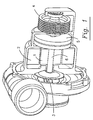
- Fig. 1 shows a supercharger/generator combination, wherein an MLC motor, comprising rotor 1 and stator 2, can be used to drive a compressor 3 as required.
- the MLC motor can be powered by batteries, by a generator associated with an internal combustion motor, or by a fuel cell.
- the MLC motor can be switched via power control electronics (see Fig. 3) to serve as an MLC electricity generator driven by positive torque from the crankshaft of an internal combustion engine (of the periodic combustion type, preferably an internal combustion engine of a hybrid combustion/electric vehicle) via a belt and pulley 4 arrangement or mechanically driven by a gear or plurality of gears driven by the engine.
- a variable drive clutch 5 is provided between the pulley 4 and the rotor shaft 6 to permit disengagement of the pulley when compressor wheel and pulley rotational speeds are intended to be different.
- the pulley when engaged, allows a belt 7 (see Fig.
- the pulley can be driven at about, e.g., a 3.45:1 ratio relative to the engine crankshaft, for increased rotational speed of the generator rotor / compressor wheel, relative to engine speed.
- a 3.45:1 ratio relative to the engine crankshaft, for increased rotational speed of the generator rotor / compressor wheel, relative to engine speed.
- other ratios can be used.
- element 1 is described herein as the rotor and element 2 is described as the stator, it is possible to construct a motor/generator wherein the rotor is a hollow cylinder rotating about a stator fixed axially within the rotor.
- the MLC motor driven rotary compressor is provided in a system in combination with a separate electric generator driven by an internal combustion engine, wherein not only the supercharger but also the generator is of MLC technology.
- the generator and the motor are connected via power control electronics to provide high compressor / generator speeds and high levels of compressor power consumption as needed.
- the system is particularly suitable for use in Hybrid Electric Vehicles (HEV), particularly for meeting the battery charging and steady state operation requirements.
- HEV Hybrid Electric Vehicles
- the MLC generator is driven via mechanical attachment to the engine crankshaft, preferably coupled via a pulley and one-way clutch arrangement.
Landscapes
- Engineering & Computer Science (AREA)
- Mechanical Engineering (AREA)
- General Engineering & Computer Science (AREA)
- Power Engineering (AREA)
- Physics & Mathematics (AREA)
- Electromagnetism (AREA)
- Supercharger (AREA)
Abstract
Description
- The present invention is concerned with a supercharger driven by an ultra high speed electric motor, having high efficiency and providing true air boost on demand.
- Mechanically driven superchargers are characterized by high efficiency, but suffer from response lag.
- It is well known to use an electric motor to drive a supercharger type compressor. See, e.g., US Patent 4,724,817 (Cook). A major drawback associated with the use of electric motors to drive rotating impeller compressors has been the linkage between the electric motor and the compressor impeller. That is, a given compressor will have a specific speed of rotation of the impeller in order to achieve the compression duty required of it. At the same time, an induction electric motor will have an optimum speed of rotation, at which the torque output is at a maximum (and which speed of rotation is generally far lower than the operating speed of high speed centrifugal compressors). Heretofore, in order to link the compressor with an electric drive motor, it has been necessary to employ an arrangement of one or more expensive gear assemblies in the compressor drive. In this way the different optimum speeds of rotation of the compressor and the electric motor can be accommodated. However, gearing increases expense, reduces reliability, and increases inertia thus reducing responsiveness.
- The design and operation of a basic electromotor driven supercharger is disclosed, e.g., in US Patent 4,838,234 (Mayer). The shaft of an electric motor is effectively connected to the rotor shaft of a free-running pressure wave supercharger for an internal combustion engine via a free-wheel overrunning clutch. In order to start a supercharged internal combustion engine, the electric motor accelerates the cell rotor (in the case of a diesel engine, for example, during the short preheating period) to a rotational speed which ensures a functioning pressure wave process immediately after the diesel engine starts. The cell rotor is then further accelerated by the exhaust gases of the diesel engine and then releases itself from the drive connection with the electric motor, which has been put out of operation in the meantime. The electromotor is thus merely a "primer" and does not appear to be capable of rotation at ultra high speed (above 20,000 RPM).
- US Patent 6,193,473 (Mruk, et al) overcomes the above problem by using a switched reluctance motor to drive the rotating centrifugal impeller of a compressor at ultrahigh speed with no gearing and with the electric motor and compressor directly linked. The present inventor considered that the drive means disclosed in Mruk, et al would be expensive, difficult to regulate particularly at lower pressures, difficult to integrate into a compact compressor of a vehicle propulsion system, and difficult to maintain.
- The present invention was made after an extensive search for a drive means capable of driving a supercharger type compressor at ultra high speed, yet providing high reliability and low product life cost despite road vibrations, engine vibrations, rapid changes in loads and speeds, and changes in temperatures to which superchargers are subjected, and wherein the drive means is simple in design and easy to manufacture.
- These objectives were accomplished, and present invention was made, based on the discovery that these and other surprising benefits can be obtained when using magnetically loaded composite (MLC) rotor technology in the design and construction of the electric motor for driving a supercharger type compressor.
- In a preferred embodiment, the MLC motor is located centrally on the rotor shaft, a pulley is provided at one end of the rotor shaft, and a compressor wheel is provided at the other end of the rotor shaft, with the MLC motor also functioning as a magnetic bearing. The system is as efficient as a mechanically driven system, yet is highly superior in that it provides true on-demand air boost.
- [00010] The MLC motor may be switched via power electronics to work as an electricity generator. In the motor/generator embodiment, the rotor is connected via a clutching device to a pulley, which allows a belt to provide compressor power and generator drive from the engine crankshaft pulley at high compressor / generator speeds and high levels of compressor power consumption. Such a design is not only simple to construct, it is also compact, stable, highly reliable, and highly responsive.
- [00011] In a further embodiment of the invention, the MLC motor driven rotary compressor is provided in a system, such as a vehicle propulsion system, together with a separate generator connected to the main engine of the propulsion system, wherein both the supercharger motor and the generator are of MLC technology. The generator and the motor are connected via power control electronics to provide high compressor / generator speeds and high levels of compressor power consumption as needed.
- [00012] The foregoing has outlined rather broadly the more pertinent and important features of the present invention in order that the detailed description of the invention that follows may be better understood, and so that the present contribution to the art can be more fully appreciated. Additional features of the invention will be described hereinafter, which form the subject of the claims of the invention. It should be appreciated by those skilled in the art that the conception and the specific embodiments disclosed may be readily utilized as a basis for modifying or designing other electric motor driven compressors for carrying out the same purposes of the present invention. It should also be realized by those skilled in the art that such equivalent structures do not depart from the spirit and scope of the invention as set forth in the appended claims.
- [00013] For a fuller understanding of the nature and objects of the present invention reference should be made by the following detailed description taken in with the accompanying drawings in which:
- Fig. 1
- is a schematic showing a MLC powered supercharger compressor with a pulley for connecting to an engine crankshaft;
- Fig. 2
- shows a simplified cross-section through the supercharger of Fig. 1, with a belt attached to the pulley; and
- Fig. 3
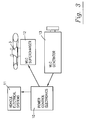
- is a schematic showing the arrangement of an alternative embodiment of the invention, with separate MLC supercharger and MLC generator.
- [00014] The present invention provides a supercharger type compressor driven at high RPM by a magnetically loaded composite (MLC) motor, and preferably also driven as needed, e.g., at peak load or when used as a generator, by an automobile internal combustion engine via a belt and clutched pulley.
- [00015] MLC incorporates magnetic material into high strength and high integrity fibrous composite structures. Fiber reinforced composites containing magnetic material for rotating components are known in general - see, e.g., GB 1370655 and U.S. Pat. No. 4,508,567; however, these prior art devices are essentially designed for low speed applications and are unsuitable for rotating at the same speed as the compressor wheel of a supercharger, and thus are not suitable for direct driving of a supercharger type compressor at high RPM.
- [00016] The MLC rotors employed in the present invention are of the type providing high electrical efficiency and ultra-high speed capacity in an electric motor/generator.
- [00017] An example of an ultra high speed MLC motor is disclosed in US Patent 5,477,092 (Tarrant), the disclosure of which is incorporated herein by reference. This patent discloses that, because of the light weight of the rotor, extremely high rotational speeds can be attained, i.e., above 20,000 RPM, and even above 100,000 RPM.
- [00018] Commercially, MLC motors are available from Urenco Ltd., Marlow, UK. A patent directed to a method for magnetizing a cylindrical body especially for use in rotors in electrical devices is disclosed in US Patent 6,154,352 (Atallah) assigned to Urenco Ltd., the disclosure of which is incorporated herein by reference. As described therein, by providing the magnetic material in separate discrete segments supported by bounding layers, instead of forming the magnetic material as cells within a composite body as in Tarrant, the magnetic loading can be substantially enhanced, the body is easier to magnetize uniformly and the segments can, if desired, be magnetized separately providing far greater flexibility in the magnetic patterning of the cylindrical body.
- [00019] As far as the present inventors are aware, literature describes MLC as useful for motor generator rotors, high surface speed generators, flywheels, dynamometers, self-driven rollers, transducers (linear, rotary and acoustic), actuators (linear and rotary), and magnetic bearings (passive and active). However, MLC motors have never been used for the purposes of the present invention.
- [00020] Benefits of MLC include weight reduction, simplified integral design, high speed, low inertia, greater quietness both mechanically & electrically, potential to reduce motor air gaps, reduced high frequency losses, i.e., no laminations, versatile magnetic patterns and numbers of poles, no PM stray fields, elimination of the back iron requirement, magnetically anisotropic/isotropic, high specific strength and stiffness, and good resistance to corrosion and chemicals. As described in US Patent 6,154,352, the use of composites can provide a material of relatively high Youngs Modulus but with far lower density, thus providing a stiffness and strength to weight ratio which is 3 to 9 times that of steel. This obviously permits high speeds and fast acceleration.
- [00021] A further benefit of MLC technology is that the MLC stator and rotor can also serve as a magnetic bearing, eliminating (at least in part) the need for roller bearings which are liable to generate noise and to wear. In the preferred embodiment shown in Fig. 1, the pulley axle is of course mounted on roller bearings.
- [00022] In the MLC motor the rotor may comprise a fiber-reinforced plastics material incorporating (preferably hard) magnetic filler material, the fiber-reinforced plastics material being arranged as a multi-layered cylindrical portion of the rotor, the magnetic filler material being disposed within and between the layers. The cylindrical portion may be a hollow tubular portion, and may be enclosed in a separate wear resistant, layer.
- [00023] Rotors of the present invention beneficially allow an efficient electromagnetic interaction between the rotor and a neighboring stator to be maintained along the length of the body of the rotor, and out-of-balance regions in the rotating mass can be avoided when the rotor is employed at high speeds.
- [00024] The plastics material may be a thermosetting or cold setting or thermoplastic polymeric material, e.g. selected from one or more of epoxy resins, polyester resins, Friedel Crafts resins, polyimides, polyamides, polyether sulfones and polyether ketones (PEEK) optionally together with known hardeners, fillers and the like. The fibers may be wound as a collection in tows. They may be wound helically and/or in hooped fashion. within the composite.
- [00025] Preferably, the fibers comprise carbon fibers, or may comprise glass fibers, or KEVLAR (polyaramid) plastics or aluminum tape, boron, nylon, polyolefin or mixtures of these or any other suitable known fibers.
- [00026] The magnetic material employed as the said magnetic filler material may be in the form of particles, spheroids, whiskers, fibers or the like, with powder being preferred. The magnetic material may comprise iron, nickel, cobalt or an alloy containing one or more of these. It may comprise a ferrite, e.g. barium ferrite. Alternatively, and preferably, the material comprises a known hard magnetic material (i.e., hard to de-magnetise) comprising a rare-earth element such as cobalt-samarium or neodymium-boron. The magnetic material may suitably be incorporated between tows of fibers within the composite.
- [00027] Since the electric motor driven supercharger can be made more responsive, the need for devices such as storage batteries and inertial flywheels is reduced, thereby reducing vehicle weight and improving fuel economy.
- [00028] The electromotor driven compressor can be regulated with almost instantaneous response. Regulating can be in response to vehicle electrical consumption, pressure at the engine intake or exhaust, or in response to fuel gas input into a fuel cell, temperature, gas pedal or brake pedal position, or any combination of these or other inputs.
- [00029] The power control electrics are preferably insulated gate bipolar transistors (IGBT). IGBT combine the positive attributes of BJTs and MOSFETs. BJTs have lower conduction losses in the on-state, especially in devices with larger blocking voltages, but have longer switching times, especially at turn-off while MOSFETs can be turned on and off much faster, but their on-state conduction losses are larger, especially in devices rated for higher blocking voltages. Hence, IGBTs have lower on-state voltage drop with high. IGBTs feature many desirable properties including a MOS input gate, high switching speed, low conduction voltage drop, high current carrying capability, and a high degree of robustness. Devices have drawn closer to the 'ideal switch', with typical voltage ratings of 600 - 1700 volts, on-state voltage of 1.7-2.0 volts at currents of up to 1000 amperes, and switching speeds of 200 - 500 ns. The availability of IGBTs has lowered the cost of systems and enhanced the number of economically viable applications
- [00030] Turning now to the figures, Fig. 1 shows a supercharger/generator combination, wherein an MLC motor, comprising rotor 1 and
stator 2, can be used to drive acompressor 3 as required. The MLC motor can be powered by batteries, by a generator associated with an internal combustion motor, or by a fuel cell. - [00031] It is also possible for the MLC motor to be switched via power control electronics (see Fig. 3) to serve as an MLC electricity generator driven by positive torque from the crankshaft of an internal combustion engine (of the periodic combustion type, preferably an internal combustion engine of a hybrid combustion/electric vehicle) via a belt and
pulley 4 arrangement or mechanically driven by a gear or plurality of gears driven by the engine. Avariable drive clutch 5 is provided between thepulley 4 and therotor shaft 6 to permit disengagement of the pulley when compressor wheel and pulley rotational speeds are intended to be different. The pulley, when engaged, allows a belt 7 (see Fig. 2), preferably a multivee belt, to provide compressor power and generator drive from the engine crankshaft pulley at high compressor / generator speeds and high levels of compressor power consumption. The pulley can be driven at about, e.g., a 3.45:1 ratio relative to the engine crankshaft, for increased rotational speed of the generator rotor / compressor wheel, relative to engine speed. Of course, other ratios can be used. - [00032] Although element 1 is described herein as the rotor and
element 2 is described as the stator, it is possible to construct a motor/generator wherein the rotor is a hollow cylinder rotating about a stator fixed axially within the rotor. - [00033] In a preferred embodiment of the invention as shown in Fig. 3, the MLC motor driven rotary compressor is provided in a system in combination with a separate electric generator driven by an internal combustion engine, wherein not only the supercharger but also the generator is of MLC technology. The generator and the motor are connected via power control electronics to provide high compressor / generator speeds and high levels of compressor power consumption as needed.
- [00034] The advantages of such a system include the following:
- [00035] The supercharger operation is independent of the crankshaft operation speed or vehicle exhaust flow mass, thus the system is highly responsive.
- [00036] The rotor and stator of both the supercharger and the generator are highly energy efficient.
- [00037] The system is particularly suitable for use in Hybrid Electric Vehicles (HEV), particularly for meeting the battery charging and steady state operation requirements.
- [00038] The MLC generator is driven via mechanical attachment to the engine crankshaft, preferably coupled via a pulley and one-way clutch arrangement.
- [00039] Advantages of the overall system include high electrical efficiencies - competitive with mechanical drive in efficiency - yet superior in responsiveness and weight reduction as discussed above. The system provides true air boost on demand. [00040] Although a MLC motor driven supercharger has been described herein with great detail, with respect to internal combustion engine powered vehicles, it will be readily apparent that the supercharger is suitable for use in a number of other applications such as hybrid or fuel cell vehicles. Although this invention has been described in its preferred form with a certain of particularity with respect to an automotive internal combustion compressor wheel, it is understood that the present disclosure of the preferred form has been made only by way of example and that numerous changes in the details of structures and the composition of the combination may be resorted to without departing from the spirit and scope of the invention.
- [00041] Now that the invention has been described,
Claims (14)
- A compressor assembly comprising:a magnetically loaded composite motor including a stator and a magnetically loaded composite rotor (1), said rotor (1) mounted on a rotatable drive shaft (6);a compressor comprising a compressor casing including a fluid inlet and a fluid outlet, said compressor further comprising an impeller (3) located within said compressor casing and mounted on said drive shaft (6).
- A compressor assembly as in claim 1, wherein said magnetically loaded composite motor is designed for operating at a speed above 20,000 RPM.
- A compressor assembly as in claim 1, further comprising a pulley (4) mounted fixed against rotation on the rotor shaft (6).
- A compressor assembly as in claim 3, wherein said impeller (3) is mounted on said drive shaft on one side of said rotor (1), and said pulley (4) is mounted on said drive shaft (6) on the opposite side of said rotor (1).
- A compressor assembly as in claim 1, further comprising a pulley coupelable to said rotor shaft via a variable drive clutch.
- A compressor assembly as in claim 1, wherein said magnetically loaded composite motor serves as a magnetic bearing system.
- A compressor assembly as in claim 1, wherein said magnetically loaded composite motor is switchable via power electronics to function as an electricity generator.
- A compressor as in claim 1, wherein said magnetically loaded composite rotor (1) is formed of a material selected from the group consisting of iron, nickel, cobalt and alloys including one of iron, nickel, and cobalt.
- A compressor as in claim 1, wherein said magnetically loaded composite rotor (1) is formed of a material selected from the group consisting of barium ferrite, cobalt-samarium and neodymium-boron.
- A compressor as in claim 1, wherein said magnetically loaded composite rotor (1) is formed of magnetic particles, spheroids, wiskers or fibers incorporated in a thermosetting, cold setting or thermoplastic polymeric material.
- A compressor as in claim 10, wherein said polymeric material is selected from the group consisting of epoxy resins, polyester resins, Friedel Crafts resins, polyimides, polyamides, polyether sulfones and polyether ketones.
- A compressor as in claim 10, wherein said magnetically loaded composite rotor (1) further includes fibers selected from the group consisting of carbon fibers, glass fibers, polyaramid plastics, aluminum, boron, nylon, polyolefin and mixtures thereof.
- A vehicle propulsion system comprising:wherein said generator and said supercharger both include a magnetic loaded composite rotor.a propulsion engine;a generator connected to said propulsion engine for generating electricity;a supercharger for boosting air flow to said propulsion engine;
- A vehicle propulsion system as in claim 13, wherein said propulsion system is selected from the group consisting of an internal combustion engine and a fuel cell system.
Applications Claiming Priority (2)
| Application Number | Priority Date | Filing Date | Title |
|---|---|---|---|
| US8084 | 2001-11-08 | ||
| US10/008,084 US20030084888A1 (en) | 2001-11-08 | 2001-11-08 | Supercharger type compressor/generator with magnetically loaded composite rotor |
Publications (2)
| Publication Number | Publication Date |
|---|---|
| EP1310677A2 true EP1310677A2 (en) | 2003-05-14 |
| EP1310677A3 EP1310677A3 (en) | 2003-11-26 |
Family
ID=21729713
Family Applications (1)
| Application Number | Title | Priority Date | Filing Date |
|---|---|---|---|
| EP02021836A Withdrawn EP1310677A3 (en) | 2001-11-08 | 2002-09-27 | Supercharger |
Country Status (2)
| Country | Link |
|---|---|
| US (1) | US20030084888A1 (en) |
| EP (1) | EP1310677A3 (en) |
Cited By (5)
| Publication number | Priority date | Publication date | Assignee | Title |
|---|---|---|---|---|
| WO2005054679A1 (en) * | 2003-12-02 | 2005-06-16 | Famatec S.P.A. | Suction pump for lifting equipment |
| WO2009154880A1 (en) * | 2008-06-20 | 2009-12-23 | Cameron International Corporation | Gas compressor magnetic coupler |
| WO2010022828A1 (en) * | 2008-08-29 | 2010-03-04 | Daimler Ag | Air supply unit for a fuel cell |
| WO2011154097A1 (en) * | 2010-06-10 | 2011-12-15 | Ebm-Papst St. Georgen Gmbh & Co. Kg | Sensor fan with integration of the air-guiding housing into the magnetic return path region of the motor stator |
| US8863646B2 (en) | 2008-09-08 | 2014-10-21 | Ge Oil & Gas Compression Systems, Llc | Compression system having seal with magnetic coupling of pistons |
Families Citing this family (11)
| Publication number | Priority date | Publication date | Assignee | Title |
|---|---|---|---|---|
| US7128061B2 (en) * | 2003-10-31 | 2006-10-31 | Vortech Engineering, Inc. | Supercharger |
| EP2302172A1 (en) | 2004-11-12 | 2011-03-30 | Board of Trustees of Michigan State University | Machine comprising an electromagnetic woven rotor and manufacturing method |
| US7591254B2 (en) * | 2007-03-28 | 2009-09-22 | Billy Machner | Supercharger control system |
| US20110074231A1 (en) * | 2009-09-25 | 2011-03-31 | Soderberg Rod F | Hybrid and electic vehicles magetic field and electro magnetic field interactice systems |
| JP5766277B2 (en) * | 2010-04-19 | 2015-08-19 | ピールブルグ パンプ テクノロジー ゲゼルシャフト ミット ベシュレンクテル ハフツングPierburg Pump Technology GmbH | Electric refrigerant pump used in automobiles |
| USD732081S1 (en) | 2014-01-24 | 2015-06-16 | Eaton Corporation | Supercharger |
| JP6344102B2 (en) * | 2014-07-14 | 2018-06-20 | 株式会社豊田自動織機 | Electric turbocharger |
| US10808701B2 (en) | 2016-02-04 | 2020-10-20 | Eaton Corporation | Cartridge style front cover and coupling cavity sleeve for automotive supercharger |
| USD855657S1 (en) | 2016-03-21 | 2019-08-06 | Eaton Corporation | Front cover for supercharger |
| US20180274551A1 (en) * | 2017-03-21 | 2018-09-27 | Borgwarner Inc. | Forced induction device with insert for reduced flow capacity |
| CN114876825A (en) | 2017-03-24 | 2022-08-09 | 江森自控泰科知识产权控股有限责任合伙公司 | Magnetic bearing motor compressor |
Citations (7)
| Publication number | Priority date | Publication date | Assignee | Title |
|---|---|---|---|---|
| GB1370655A (en) | 1970-11-16 | 1974-10-16 | Crouzet Sa | Method of manufacture of a permanent magnet rotor for a synchronous motor |
| US4508567A (en) | 1981-07-02 | 1985-04-02 | Brother Kogyo Kabushiki Kaisha | Press-molding process for preparing a powder compact |
| US4724817A (en) | 1987-01-20 | 1988-02-16 | Gpn Enterprises | Apparatus and technique for supercharging combustion engines |
| US4838234A (en) | 1987-04-16 | 1989-06-13 | Bbc Brown Boveri Ag | Free-running pressure wave supercharger |
| US5477092A (en) | 1992-09-07 | 1995-12-19 | British Nuclear Fuels Plc | Rotor |
| US6154352A (en) | 1996-03-29 | 2000-11-28 | Urenco (Capenhurst) Limited | Method of magnetizing a cylindrical body |
| US6193473B1 (en) | 1999-03-31 | 2001-02-27 | Cooper Turbocompressor, Inc. | Direct drive compressor assembly with switched reluctance motor drive |
Family Cites Families (3)
| Publication number | Priority date | Publication date | Assignee | Title |
|---|---|---|---|---|
| US4147396A (en) * | 1977-02-22 | 1979-04-03 | Cambridge Thermionic Corporation | High speed rotor system |
| WO1996031934A1 (en) * | 1995-04-03 | 1996-10-10 | Sulzer Electronics Ag | Rotary machine with an electromagnetic rotary drive |
| US5906098A (en) * | 1996-07-16 | 1999-05-25 | Turbodyne Systems, Inc. | Motor-generator assisted turbocharging systems for use with internal combustion engines and control method therefor |
-
2001
- 2001-11-08 US US10/008,084 patent/US20030084888A1/en not_active Abandoned
-
2002
- 2002-09-27 EP EP02021836A patent/EP1310677A3/en not_active Withdrawn
Patent Citations (7)
| Publication number | Priority date | Publication date | Assignee | Title |
|---|---|---|---|---|
| GB1370655A (en) | 1970-11-16 | 1974-10-16 | Crouzet Sa | Method of manufacture of a permanent magnet rotor for a synchronous motor |
| US4508567A (en) | 1981-07-02 | 1985-04-02 | Brother Kogyo Kabushiki Kaisha | Press-molding process for preparing a powder compact |
| US4724817A (en) | 1987-01-20 | 1988-02-16 | Gpn Enterprises | Apparatus and technique for supercharging combustion engines |
| US4838234A (en) | 1987-04-16 | 1989-06-13 | Bbc Brown Boveri Ag | Free-running pressure wave supercharger |
| US5477092A (en) | 1992-09-07 | 1995-12-19 | British Nuclear Fuels Plc | Rotor |
| US6154352A (en) | 1996-03-29 | 2000-11-28 | Urenco (Capenhurst) Limited | Method of magnetizing a cylindrical body |
| US6193473B1 (en) | 1999-03-31 | 2001-02-27 | Cooper Turbocompressor, Inc. | Direct drive compressor assembly with switched reluctance motor drive |
Cited By (6)
| Publication number | Priority date | Publication date | Assignee | Title |
|---|---|---|---|---|
| WO2005054679A1 (en) * | 2003-12-02 | 2005-06-16 | Famatec S.P.A. | Suction pump for lifting equipment |
| WO2009154880A1 (en) * | 2008-06-20 | 2009-12-23 | Cameron International Corporation | Gas compressor magnetic coupler |
| US9482235B2 (en) | 2008-06-20 | 2016-11-01 | Ingersoll-Rand Company | Gas compressor magnetic coupler |
| WO2010022828A1 (en) * | 2008-08-29 | 2010-03-04 | Daimler Ag | Air supply unit for a fuel cell |
| US8863646B2 (en) | 2008-09-08 | 2014-10-21 | Ge Oil & Gas Compression Systems, Llc | Compression system having seal with magnetic coupling of pistons |
| WO2011154097A1 (en) * | 2010-06-10 | 2011-12-15 | Ebm-Papst St. Georgen Gmbh & Co. Kg | Sensor fan with integration of the air-guiding housing into the magnetic return path region of the motor stator |
Also Published As
| Publication number | Publication date |
|---|---|
| EP1310677A3 (en) | 2003-11-26 |
| US20030084888A1 (en) | 2003-05-08 |
Similar Documents
| Publication | Publication Date | Title |
|---|---|---|
| US20030084888A1 (en) | Supercharger type compressor/generator with magnetically loaded composite rotor | |
| US8544575B1 (en) | Lightweight internal combustion/electric hybrid power source for vehicles | |
| US8820286B2 (en) | Lightweight portable electric generator with integrated starter/alternator | |
| AU2010295220B2 (en) | A matrix material comprising magnetic particles for use in hybrid and electric vehicles | |
| US8653677B2 (en) | Electromagnetic, continuously variable transmission power split turbo compound and engine and vehicle comprising such a turbo compound | |
| EP0141634A2 (en) | Engine with exhaust energy recovery device and generator device for use with the engine | |
| JP3889050B2 (en) | Turbocharger system with integrated assist electric motor and its cooling system | |
| CN1211300A (en) | Motor-generator assisted turbocharging systems for use with internal combustion engines and control systems | |
| US8176901B2 (en) | Variable speed supercharger with electric power generation | |
| EP0243187A2 (en) | Electric generator for use in a turbocharger and turbocharger including said generator | |
| US20170126087A1 (en) | Device including material originating from magnetic particles providing structural and magnetic capabilities | |
| EP1233179A2 (en) | Composite drive system for compressor | |
| KR19990046150A (en) | Motor-assisted supercharging devices for internal combustion engines | |
| JPH03115739A (en) | Turbocharger with rotary electric machine | |
| EP1237256A2 (en) | Drive force transmission for vehicle ac generator | |
| CN1249862A (en) | Improvement in high speed electric motors | |
| US5912516A (en) | High speed alternator/motor | |
| WO2003040567A1 (en) | Two stage electrically powered compressor | |
| US20040247461A1 (en) | Two stage electrically powered compressor | |
| EP1860759A2 (en) | Axial Gap alternator | |
| US6865888B2 (en) | Turbocharger for an internal combustion engine with pistons | |
| CN106471285B (en) | Variable power transmission | |
| CN2675889Y (en) | Combined flywheel driven by hybrid power | |
| KR20040009042A (en) | Turbocharging System Having Turbocharger Integrated with Generator | |
| WO2005112235A1 (en) | Hybrid propulsion system |
Legal Events
| Date | Code | Title | Description |
|---|---|---|---|
| PUAI | Public reference made under article 153(3) epc to a published international application that has entered the european phase |
Free format text: ORIGINAL CODE: 0009012 |
|
| AK | Designated contracting states |
Designated state(s): AT BE BG CH CY CZ DE DK EE ES FI FR GB GR IE IT LI LU MC NL PT SE SK TR |
|
| AX | Request for extension of the european patent |
Extension state: AL LT LV MK RO SI |
|
| PUAL | Search report despatched |
Free format text: ORIGINAL CODE: 0009013 |
|
| AK | Designated contracting states |
Kind code of ref document: A3 Designated state(s): AT BE BG CH CY CZ DE DK EE ES FI FR GB GR IE IT LI LU MC NL PT SE SK TR |
|
| AX | Request for extension of the european patent |
Extension state: AL LT LV MK RO SI |
|
| RIC1 | Information provided on ipc code assigned before grant |
Ipc: 7H 02K 7/09 B Ipc: 7F 04D 25/02 B Ipc: 7F 04D 25/06 B Ipc: 7F 04D 29/04 A |
|
| AKX | Designation fees paid |
Designated state(s): DE FR GB IT NL |
|
| STAA | Information on the status of an ep patent application or granted ep patent |
Free format text: STATUS: THE APPLICATION IS DEEMED TO BE WITHDRAWN |
|
| 18D | Application deemed to be withdrawn |
Effective date: 20040527 |