EP1310463A2 - Method for fabricating silica glass using sol-gel process - Google Patents
Method for fabricating silica glass using sol-gel process Download PDFInfo
- Publication number
- EP1310463A2 EP1310463A2 EP02019750A EP02019750A EP1310463A2 EP 1310463 A2 EP1310463 A2 EP 1310463A2 EP 02019750 A EP02019750 A EP 02019750A EP 02019750 A EP02019750 A EP 02019750A EP 1310463 A2 EP1310463 A2 EP 1310463A2
- Authority
- EP
- European Patent Office
- Prior art keywords
- gel
- sol
- chamber
- heat treatment
- heat chamber
- Prior art date
- Legal status (The legal status is an assumption and is not a legal conclusion. Google has not performed a legal analysis and makes no representation as to the accuracy of the status listed.)
- Withdrawn
Links
Images




Classifications
-
- C—CHEMISTRY; METALLURGY
- C03—GLASS; MINERAL OR SLAG WOOL
- C03B—MANUFACTURE, SHAPING, OR SUPPLEMENTARY PROCESSES
- C03B19/00—Other methods of shaping glass
- C03B19/12—Other methods of shaping glass by liquid-phase reaction processes
Definitions
- the present invention relates to a method for fabricating silica glass.
- the present invention relates to a method for fabricating silica glass using a sol-gel process.
- optical communication systems have drawn a lot of attention in the relevant industries because these systems successfully perform at very high transmission speeds with little loss of optical signals.
- Such optical communication systems typically use an optical fiber fetched from a perform made of silica glass as a transmission media.
- the silica glass is fabricated by one of a natural quartz process, synthetic quartz process, or sol-gel process. More details on the sol-gel process can be found in U.S. Pat. No. 5,240, 488.
- Figure 1 provides a flowchart providing an overview of a method for fabricating silica glass using a sol-gel process according to the prior art.
- the fabrication method includes a sol forming step 110, a sol filling step 120, a gel drying step 130, a low heat treatment step 140, and a sintering step 150.
- the sol forming step 110 involves mixing a starting material, deionized water, and an additive to form a sol.
- a starting material a fumed silica or silicon alkoxide can be used.
- an additive any of a dispersion agent, a catalyst or a binder can be used.
- the sol filling step 120 involves filling a circular mold with the sol produced by the forming step 110.
- the circular mold has a cylindrical shape, and a separable rod is arranged at the center of the circular mold. That is to say, the sol fills the inside of the circular mold except for the rod. Later, the sol is gelatinized inside of the circular mold.
- the gel drying step 130 involves drying the gel after separating the gel from the circular mold.
- the gel drying step 130 is performed in a temperature and humidity chamber that maintains a constant temperature and relative humidity.
- the dried gel is placed in a low-heating device, and goes through a heat treatment at a temperature of 900°C at the presence of chlorine gas which is injected to the inside of the low heat device. Afterwards, the remaining moisture inside of the gel and other organic matters like the binder are decomposed, and any metallic impurities and hydroxyl radicals (OH) in the gel are removed.
- the sintering step 150 involves performing a vitrification process on the gel by applying heat to the gel subsequent to performing the low heat treatment step 140.
- the sintering step 150 is performed by heating the dry gel at a temperature over 1300°C and moving the gel up and down in the sintering furnace under helium (He) gas or vacuum atmosphere.
- He helium
- Figure 2 graphically illustrates scattering characteristics of the silica glass according to the prior art.
- the graph was obtained by mounting a sample of the silica glass on a spectrometer, and light was made incident onto one side of the sample, and a spectrum analysis was made of the transmitted light.
- the scattering distance indicates a relative measurement position
- the scattering intensity indicates the intensity of the scattered light at a corresponding measurement position.
- a large number of points appear with a maximum intensity being dependent on the measurement position. Each maximum intensity point exhibits a maximum scattering intensity at the corresponding measurement position.
- Such scattering phenomenon is caused by micro bubbles existing inside of the silica glass.
- the low heat treatment step was originally carried out on the gel in a chlorine gas atmosphere in order to decompose the remaining moisture and organic matters, such as the binder inside of the gel, and to remove any metallic impurities and hydroxyl radicals (OH).
- OH hydroxyl radicals
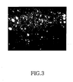
- Figure 3 is a view illustrating part of a fault of the silica glass fabricated in accordance with the related art.
- the white spots are the micro bubbles formed in the silica glass.
- the micro bubbles are the reason that the optical signals that are supposed to progress inside of the silica glass are scattered, and the cracking and micro-bending of the silica glass occur due to the changes in the ambient temperature.
- the major problem of the traditional method for fabricating silica glass using a sol-gel process is that micro bubbles are produced inside of the silica glass because of the remaining chlorine gas after the low heat treatment step.
- a primary object of the present invention to provide a method for fabricating silica glass using a sol-gel process that enables to suppress formation of micro bubbles inside of the silica glass, and to decrease the number and size of the micro bubbles.
- a method for fabricating silica glass using a sol-gel process which includes sol forming step for forming a sol by mixing a starting material, deionized water and an additive; a gelation step for gelatinizing the sol after filling a mold with the gel produced; a gel drying step for separating the gel from the mold and drying the gel; a setting step for placing the gel inside of a heat chamber and injecting helium gas into the heat chamber; and a low heat treatment step including repeatedly pressurizing and depressurizing the heat chamber several times.
- Figure 4 is a diagrammatic view showing a method for fabricating silica glass using a sol-gel process according to a preferred embodiment of the present invention.
- the fabrication method includes a sol forming step 210, a sol filling step 220, a gel drying step 230, allow heat treatment step 240, and a sintering step 250.
- the sol forming step 210 involves mixing a starting material, deionized water, and an additive to form a sol.
- a starting material a fumed silica or silicon alkoxide can be used.
- an additive a dispersion agent, catalyst or binder can be used.
- the sol filling step 220 involves filling a circular mold with the sol produced by the sol forming step 210.
- the circular mold has a cylindrical shape, and a separable rod is positioned at the center of the circular mold. That is to say, the sol fills the inside of the circular mold except for the rod. Later, the sol is gelatinized inside of the circular mold.
- the gel drying step 230 involves drying the gel after separating the gel from the circular mold.
- the gel drying step 230 is performed in a temperature and humidity chamber that maintains a constant temperature and relative humidity.
- FIG. 5 is a schematic diagram showing a system for carrying out the low heat treatment step 240.
- the system includes a low heat treatment device 320; a pressurizing device 370 being connected to an internal heat chamber 330 through an induction pipe 380; a depressurizing device 390 being connected to internal heat chamber 330 through an exhaust pipe 400; a throttle valve 410; and a switch 420.
- the low heat treatment device 320 includes the heat chamber 330 at the upper portion of the device, and a control panel 340 at the low portion of the device.
- the heat chamber 330 is mounted with a heater (not shown) and a cooler (not shown), through which a user can optionally adjust the internal temperature.
- a preferable heater that can be suitable for use can be a heating wire or a heating plate mounted on the inside of the heat chamber 330.
- the internal temperature of the heat chamber 330 can be raised up to a predetermined temperature by applying a current to the heating wire.
- a cooling line is installed at the inside of a wall of the heat chamber 330. By circulating cooling water through the cooling line, it is possible to lower the internal temperature of the heat chamber 330 to a predetermined temperature.
- the control panel 340 is mounted with a thermometer 350 for indicating the internal temperature of the heat chamber 330, and a manometer 360 for indicating the internal pressure of the heat chamber 330.
- the pressurizing device 370 increases the internal pressure of the heat chamber 330 through the induction pipe 380.
- a preferable pressurizing device 370 is a helium tank, in which helium gas is compressed into a liquid phase, and the liquid helium is preserved in the helium tank. Since the compressed helium inside of the helium tank is at a high pressure, if one wishes to use the helium tank as the pressurizing device according to the present invention, he should depressurize the helium according to need.
- the depressurizing device 390 decreases the internal pressure of the heat chamber 330 through the exhaust pipe 400.
- a vacuum pump is used for the depressurizing device 390.
- the vacuum pump used is largely divided into three different kinds: a low vacuum pump, a high vacuum pump, and a super high vacuum pump. More specifically, the low vacuum pump is in a vacuum range of from 760 torr to 1x10 -3 torr, and the high vacuum pump is in a vacuum range of from 1x10 -3 torr to 1x10 -8 torr, and the super high vacuum pump is in a vacuum range of from 1x10 -8 torr and below.
- a rotary pump is often used. Basically, the rotary pump is lubricated to maintain the induction chamber airtight, and the air inside of the chamber is exhausted to the outside through a volume exhaust via rotation.
- an oil diffusion pump which is one of the high vacuum pumps, does not work during general atmospheric pressure conditions. In fact, the oil diffusion pump first exhausts most of air to another pump like the rotary pump, and starts to work when the vacuum pressure is at least 10 -3 torr. If the gas pressure is too high, the oil molecules might collide with other gas molecules many times and stop moving in the middle of the operation. This is why the pressure at the induction opening should be lower than 10 -3 torr.
- the super high vacuum pump can be selected from a group including titanium sublimation pump, ion pump, or non-evaporable pump. Since the vacuum degree of the depressurizing device 390 of the present invention does not have to be so high, the rotary, one of the low vacuum pumps, might as well be employed.
- the throttle valve 410 is mounted on a route of the exhaust pipe 400, opening or closing the exhaust pipe 400.
- the switch 420 depending on how a user operates, opens and closes the throttle valve 410, and also turns on/off the depressurizing device 390.
- FIG. 6 is a detailed diagram showing the low heat treatment step 240.
- the low heat treatment step includes an initial setting step 510, primary heat treatment step 520, cooling step 530, and secondary heat treatment step 540.
- the low heat treatment step 240 will now be described with reference to Figures 5 and 6.
- the dry gel 310 that went through the gel drying step 230 is placed at the inside of the heat chamber 330.
- the internal heat chamber 330 is vacuumed , andsubsequently filled with helium gas.
- the internal pressure of the heat chamber 330 is set up at somewhat higher than the atmospheric pressure, for example, 800 torr.
- the primary heat treatment step 520 involves increasing the internal temperature of the heat chamber 330 by using the heater until the temperature reaches 900°C, by way of decomposing the remaining moisture and other organic matters like the binder inside of the gel 310, and removing any metallic impurities and hydroxyl radicals (OH-).
- the cooling step 530 involves decreasing the internal temperature of the heat chamber 330 down to 600°C by using the cooler.
- the secondary heat treatment step 540 involves decreasing the internal pressure of the heat chamber 330 down to 60 torr by using the depressurizing device 390. Similarly, the internal pressure of the heat chamber can be increased to 930 torr by using the pressurizing device 370. This depressurizing and pressurizing step is repeated several times (i.e., 3 times). At this time, the internal temperature of the heat chamber 330 should maintain the temperature of 600°C.
- the sintering step 250 involves carrying out a vitrification process on the gel 310 by applying heat to it after the gel 310 went through the low heat treatment step 240.
- the sintering step 250 is carried out by heating the dry gel at a temperature over 1300°C and moving the gel up and down in the sintering furnace under the helium (He) gas or vacuum atmosphere. Once the sintering step 250 is completed, a high-purity silica glass is obtained.
- Figure 7 is a graph showing scattering characteristics of silica glass fabricated according to the present invention.
- the graph is obtained by mounting a sample of the silica glass on a spectrometer, and incidenting light onto one side of the sample, and making spectrum analysis on the transmitted light.
- the scattering distance indicates a relative measurement position
- the scattering intensity indicates the intensity of the scattered light at a corresponding measurement position.
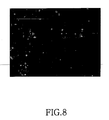
- Figure 8 diagrammatically shows part of a fault of silica glass, which is fabricated according to the present invention.
- things that look like white spots are the micro bubbles formed in the silica glass.
- the micro bubbles are the main reason why the optical signals that are supposed to progress inside of the silica glass are scattered, and the crack and micro-bending occur to the silica glass due to the changes in the ambient temperature.
- Figure 3 it is observed that the number of the micro bubbles and their size as a whole are greatly decreased.
- the method for fabricating silica glass using a sol-gel process provided by the present invention is advantageous in that it successfully suppresses the formation of micro bubbles in the silica glass and decreases the number of the micro bubbles and their size in general, by carrying out the low heat treatment step under the helium gas atmosphere and repeating the depressurizing and pressurizing step several times during the low heat treatment step.
Landscapes
- Chemical & Material Sciences (AREA)
- Engineering & Computer Science (AREA)
- Chemical Kinetics & Catalysis (AREA)
- Manufacturing & Machinery (AREA)
- Materials Engineering (AREA)
- Organic Chemistry (AREA)
- Glass Melting And Manufacturing (AREA)
- Manufacture, Treatment Of Glass Fibers (AREA)
- Silicon Compounds (AREA)
Abstract
Description
Claims (14)
- A method for fabricating silica glass having a decreased quantity and size of micro-bubbles using a sol-gel process, the method comprising:a sol forming step for forming a sol by mixing a starting material, deionized water and an additive together;a gelation step for gelatinizing the sol after filling a mold with the gel produced;a gel drying step for separating the gel from the mold and drying the gel;a setting step for placing the gel inside of a heat chamber and injecting helium gas into the heat chamber; anda low heat treatment step for pressurizing and depressurizing an internal pressure of the heat chamber repeatedly for several times.
- The method according to claim 1, further comprising a sintering step for sintering the gel that has gone through the low heat treatment by heating the gel at a high temperature.
- The method according to claims 1 or 2, wherein the low heat treatment step includes:(i) providing a primary heat treatment sub-step to heat the chamber to a first predetermined temperature;(ii) a cooling sub-step to reduce the predetermined temperature of the heat chamber to a second predetermined temperature that is lower than the first predetermined temperature;(iii) providing a secondary heat treatment sub-step by:(a) decreasing an internal pressure of the heat chamber to a predetermined value of depressurization;(b) increasing the internal pressure of the heat chamber to a subsequent predetermined value of pressurization; and(b) repeating sub-steps steps (iii) (a) and (iii) (b) for a predetermined plurality of times.
- The method according to claim 3, wherein the internal pressure is decreased in sub-step (iii)(a) to approximately 60 torr.
- The method according to claim 3, wherein the internal pressure is increased in sub-step (iii)(b) to approximately 930 torr.
- The method according to claim 3, wherein during the secondary heat treatment sub-step (iii) the temperature of the heat chamber is maintained at a constant value.
- The method according to claim 3, wherein prior to providing the primary heat treatment sub-step the pressure of the heat chamber is increased to a initial value that is higher than atmospheric pressure.
- The method according to claim 7, wherein the initial value of pressure in the heat chamber is approximately 800 torr.
- The method according to claim 3, wherein subsequent to the separation of the gel from the mold in the gel drying step, the gel is maintained at a constant temperature and relative humidity.
- The method according to claim 1 or 2, wherein the pressurizing and depressurizing is performed for repeated at least three times.
- The method according to claim 1 or 2, wherein the pressure of the heat chamber is increased above atmospheric pressure prior to the pressurizing and depressurizing step.
- The method according to claim 11, wherein the pressurizing and depressurizing occurs at a constant predetermined temperature.
- The method according to claim 12, wherein the chamber is depressurized to approximately 60 torr, pressurized to approximately 930 torr, and the chamber is maintained at approximately 600 degrees Celsius.
- Silica glass manufactured according to one of claims 2 to 13 .
Applications Claiming Priority (2)
| Application Number | Priority Date | Filing Date | Title |
|---|---|---|---|
| KR10-2001-0070583A KR100446512B1 (en) | 2001-11-13 | 2001-11-13 | Silica glass fabrication method using sol-gel process |
| KR2001070583 | 2001-11-13 |
Publications (2)
| Publication Number | Publication Date |
|---|---|
| EP1310463A2 true EP1310463A2 (en) | 2003-05-14 |
| EP1310463A3 EP1310463A3 (en) | 2004-05-19 |
Family
ID=19715952
Family Applications (1)
| Application Number | Title | Priority Date | Filing Date |
|---|---|---|---|
| EP02019750A Withdrawn EP1310463A3 (en) | 2001-11-13 | 2002-09-03 | Method for fabricating silica glass using sol-gel process |
Country Status (4)
| Country | Link |
|---|---|
| US (1) | US6860118B2 (en) |
| EP (1) | EP1310463A3 (en) |
| JP (1) | JP2003146666A (en) |
| KR (1) | KR100446512B1 (en) |
Cited By (1)
| Publication number | Priority date | Publication date | Assignee | Title |
|---|---|---|---|---|
| WO2021159839A1 (en) * | 2020-02-11 | 2021-08-19 | 深圳市绎立锐光科技开发有限公司 | Production apparatus for preparing glass by using sol-gel method, and associated preparation method |
Families Citing this family (2)
| Publication number | Priority date | Publication date | Assignee | Title |
|---|---|---|---|---|
| KR100446512B1 (en) * | 2001-11-13 | 2004-09-04 | 삼성전자주식회사 | Silica glass fabrication method using sol-gel process |
| KR20030068730A (en) * | 2002-02-16 | 2003-08-25 | 삼성전자주식회사 | Method for preventing macro bubble in sol-gel process |
Family Cites Families (20)
| Publication number | Priority date | Publication date | Assignee | Title |
|---|---|---|---|---|
| JPS5734031A (en) * | 1980-08-07 | 1982-02-24 | Toshiba Ceramics Co Ltd | Method and apparatus for decreasing number of bubbles in formed quartz glass |
| DE3039749C2 (en) * | 1980-10-22 | 1982-08-19 | Heraeus Quarzschmelze Gmbh, 6450 Hanau | Process for the production of bubble-free, glassy material |
| US4419115A (en) * | 1981-07-31 | 1983-12-06 | Bell Telephone Laboratories, Incorporated | Fabrication of sintered high-silica glasses |
| GB2165234B (en) | 1984-10-05 | 1988-09-01 | Suwa Seikosha Kk | Methods of preparing doped silica glass |
| CA1290942C (en) * | 1985-03-18 | 1991-10-22 | Michihisa Kyoto | Method for producing glass preform for optical fiber |
| CA1254238A (en) * | 1985-04-30 | 1989-05-16 | Alvin P. Gerk | Process for durable sol-gel produced alumina-based ceramics, abrasive grain and abrasive products |
| US5236483A (en) * | 1985-07-16 | 1993-08-17 | Seiko Epson Corporation | Method of preparing silica glass |
| JPS62119131A (en) * | 1985-11-18 | 1987-05-30 | Seiko Epson Corp | Production of base material for optical fiber |
| US4680049A (en) * | 1986-08-15 | 1987-07-14 | Gte Laboratories Incorporated | Process for molding optical components of silicate glass to a near net shape optical precision |
| US4789389A (en) * | 1987-05-20 | 1988-12-06 | Corning Glass Works | Method for producing ultra-high purity, optical quality, glass articles |
| JPH05147950A (en) * | 1991-12-03 | 1993-06-15 | Seiko Epson Corp | Production of glass |
| US5240488A (en) | 1992-08-14 | 1993-08-31 | At&T Bell Laboratories | Manufacture of vitreous silica product via a sol-gel process using a polymer additive |
| JP3988211B2 (en) * | 1996-06-18 | 2007-10-10 | 東ソー株式会社 | Method for producing high purity transparent silica glass |
| KR100229884B1 (en) * | 1997-03-10 | 1999-11-15 | 윤종용 | Method for producing high purity silica glass using sol-gel method |
| JPH11189427A (en) * | 1997-12-25 | 1999-07-13 | Koransha Co Ltd | Production of sintered silica glass |
| JP4022678B2 (en) * | 1998-01-23 | 2007-12-19 | 東ソー株式会社 | Method for producing high purity transparent silica glass |
| KR100313276B1 (en) * | 1999-06-09 | 2001-11-05 | 윤종용 | Heat-treatment apparatus for silica glass forming gel |
| KR100326174B1 (en) | 1999-12-31 | 2002-02-27 | 윤종용 | Fabrication method of high purity silica glass by sol-gel process |
| DK1283195T3 (en) * | 2001-08-01 | 2005-12-12 | Novara Technology Srl | Sol-gel method for preparing optical fiber preforms |
| KR100446512B1 (en) * | 2001-11-13 | 2004-09-04 | 삼성전자주식회사 | Silica glass fabrication method using sol-gel process |
-
2001
- 2001-11-13 KR KR10-2001-0070583A patent/KR100446512B1/en not_active Expired - Fee Related
-
2002
- 2002-06-25 US US10/179,704 patent/US6860118B2/en not_active Expired - Fee Related
- 2002-09-03 EP EP02019750A patent/EP1310463A3/en not_active Withdrawn
- 2002-10-30 JP JP2002316148A patent/JP2003146666A/en not_active Abandoned
Cited By (1)
| Publication number | Priority date | Publication date | Assignee | Title |
|---|---|---|---|---|
| WO2021159839A1 (en) * | 2020-02-11 | 2021-08-19 | 深圳市绎立锐光科技开发有限公司 | Production apparatus for preparing glass by using sol-gel method, and associated preparation method |
Also Published As
| Publication number | Publication date |
|---|---|
| US6860118B2 (en) | 2005-03-01 |
| EP1310463A3 (en) | 2004-05-19 |
| US20030089131A1 (en) | 2003-05-15 |
| KR100446512B1 (en) | 2004-09-04 |
| KR20030039617A (en) | 2003-05-22 |
| JP2003146666A (en) | 2003-05-21 |
Similar Documents
| Publication | Publication Date | Title |
|---|---|---|
| JP3690806B2 (en) | Subcritical drying of sol-gel porous objects | |
| KR101803765B1 (en) | Method and device for preparing aerogel by drying under reduced pressure | |
| CA1288313C (en) | Process for forming transparent aerogel insulating arrays | |
| WO1993023713A1 (en) | Vertical heat treatment apparatus and heat insulating material | |
| TWI454425B (en) | Silica, silica containers and the manufacture of such powders or containers | |
| JP2858637B2 (en) | Method for producing fused silica glass product | |
| CN112876044B (en) | Chemical deposition method and device for high-purity low-hydroxyl high-uniformity quartz glass | |
| CN1262497C (en) | Sol-Gel Method for Producing Glass Optical Fiber Preform | |
| US6884822B2 (en) | Sol-gel process utilizing reduced mixing temperatures | |
| US6860118B2 (en) | Method for fabricating silica glass using sol-gel process | |
| JPH09102488A (en) | Alumina microwave introduction window and manufacturing method thereof | |
| US20090041960A1 (en) | Method for making a silica glass crucible | |
| EP2325146A2 (en) | Method of making a silica crucible in a controlled atmosphere | |
| WO2011162403A1 (en) | Mesoporous silica film, structural body having mesoporous silica film, antireflection film, optical member, and methods of producing the same | |
| CN109679132B (en) | Microwave-assisted production method of aerogel and methyl silsesquioxane aerogel | |
| US6698054B2 (en) | Method for fabricating high-purity silica glass using sol-gel processing | |
| KR100270130B1 (en) | Method and apparatus for manufacturing glass preform | |
| JP7601085B2 (en) | Silica glass, high frequency device using silica glass, and method for manufacturing silica glass | |
| US20040041288A1 (en) | Apparatus and method for fabricating an optical fiber preform with a large aperture | |
| Hinić et al. | Influence of the synthesis conditions on the photoluminescence of silica gels | |
| JP2010163328A (en) | Method for manufacturing preform for optical fiber added with rare earth element | |
| US20040200239A1 (en) | Method and apparatus for sintering gel tube | |
| JP4421028B2 (en) | Pressure treatment device | |
| JPH02243532A (en) | Drawing furnace for fluoride optical fiber | |
| JP4704971B2 (en) | Vacuum adsorption device |
Legal Events
| Date | Code | Title | Description |
|---|---|---|---|
| PUAI | Public reference made under article 153(3) epc to a published international application that has entered the european phase |
Free format text: ORIGINAL CODE: 0009012 |
|
| 17P | Request for examination filed |
Effective date: 20020903 |
|
| AK | Designated contracting states |
Designated state(s): AT BE BG CH CY CZ DE DK EE ES FI FR GB GR IE IT LI LU MC NL PT SE SK TR |
|
| AX | Request for extension of the european patent |
Extension state: AL LT LV MK RO SI |
|
| PUAL | Search report despatched |
Free format text: ORIGINAL CODE: 0009013 |
|
| AK | Designated contracting states |
Kind code of ref document: A3 Designated state(s): AT BE BG CH CY CZ DE DK EE ES FI FR GB GR IE IT LI LU MC NL PT SE SK TR |
|
| AX | Request for extension of the european patent |
Extension state: AL LT LV MK RO SI |
|
| AKX | Designation fees paid |
Designated state(s): DE FR GB |
|
| 17Q | First examination report despatched |
Effective date: 20050613 |
|
| GRAP | Despatch of communication of intention to grant a patent |
Free format text: ORIGINAL CODE: EPIDOSNIGR1 |
|
| STAA | Information on the status of an ep patent application or granted ep patent |
Free format text: STATUS: THE APPLICATION IS DEEMED TO BE WITHDRAWN |
|
| 18D | Application deemed to be withdrawn |
Effective date: 20061228 |