EP1310392A1 - Air conditioning unit for a transport container - Google Patents
Air conditioning unit for a transport container Download PDFInfo
- Publication number
- EP1310392A1 EP1310392A1 EP02255388A EP02255388A EP1310392A1 EP 1310392 A1 EP1310392 A1 EP 1310392A1 EP 02255388 A EP02255388 A EP 02255388A EP 02255388 A EP02255388 A EP 02255388A EP 1310392 A1 EP1310392 A1 EP 1310392A1
- Authority
- EP
- European Patent Office
- Prior art keywords
- section
- cover
- nozzle
- container
- air
- Prior art date
- Legal status (The legal status is an assumption and is not a legal conclusion. Google has not performed a legal analysis and makes no representation as to the accuracy of the status listed.)
- Granted
Links
Images




Classifications
-
- F—MECHANICAL ENGINEERING; LIGHTING; HEATING; WEAPONS; BLASTING
- F25—REFRIGERATION OR COOLING; COMBINED HEATING AND REFRIGERATION SYSTEMS; HEAT PUMP SYSTEMS; MANUFACTURE OR STORAGE OF ICE; LIQUEFACTION SOLIDIFICATION OF GASES
- F25D—REFRIGERATORS; COLD ROOMS; ICE-BOXES; COOLING OR FREEZING APPARATUS NOT OTHERWISE PROVIDED FOR
- F25D17/00—Arrangements for circulating cooling fluids; Arrangements for circulating gas, e.g. air, within refrigerated spaces
- F25D17/04—Arrangements for circulating cooling fluids; Arrangements for circulating gas, e.g. air, within refrigerated spaces for circulating air, e.g. by convection
- F25D17/06—Arrangements for circulating cooling fluids; Arrangements for circulating gas, e.g. air, within refrigerated spaces for circulating air, e.g. by convection by forced circulation
- F25D17/067—Evaporator fan units
-
- B—PERFORMING OPERATIONS; TRANSPORTING
- B60—VEHICLES IN GENERAL
- B60H—ARRANGEMENTS OF HEATING, COOLING, VENTILATING OR OTHER AIR-TREATING DEVICES SPECIALLY ADAPTED FOR PASSENGER OR GOODS SPACES OF VEHICLES
- B60H1/00—Heating, cooling or ventilating devices
- B60H1/00457—Ventilation unit, e.g. combined with a radiator
- B60H1/00471—The ventilator being of the radial type, i.e. with radial expulsion of the air
-
- B—PERFORMING OPERATIONS; TRANSPORTING
- B60—VEHICLES IN GENERAL
- B60H—ARRANGEMENTS OF HEATING, COOLING, VENTILATING OR OTHER AIR-TREATING DEVICES SPECIALLY ADAPTED FOR PASSENGER OR GOODS SPACES OF VEHICLES
- B60H1/00—Heating, cooling or ventilating devices
- B60H1/32—Cooling devices
- B60H1/3204—Cooling devices using compression
- B60H1/3232—Cooling devices using compression particularly adapted for load transporting vehicles
-
- F—MECHANICAL ENGINEERING; LIGHTING; HEATING; WEAPONS; BLASTING
- F25—REFRIGERATION OR COOLING; COMBINED HEATING AND REFRIGERATION SYSTEMS; HEAT PUMP SYSTEMS; MANUFACTURE OR STORAGE OF ICE; LIQUEFACTION SOLIDIFICATION OF GASES
- F25D—REFRIGERATORS; COLD ROOMS; ICE-BOXES; COOLING OR FREEZING APPARATUS NOT OTHERWISE PROVIDED FOR
- F25D11/00—Self-contained movable devices, e.g. domestic refrigerators
- F25D11/003—Transport containers
-
- F—MECHANICAL ENGINEERING; LIGHTING; HEATING; WEAPONS; BLASTING
- F25—REFRIGERATION OR COOLING; COMBINED HEATING AND REFRIGERATION SYSTEMS; HEAT PUMP SYSTEMS; MANUFACTURE OR STORAGE OF ICE; LIQUEFACTION SOLIDIFICATION OF GASES
- F25D—REFRIGERATORS; COLD ROOMS; ICE-BOXES; COOLING OR FREEZING APPARATUS NOT OTHERWISE PROVIDED FOR
- F25D2317/00—Details or arrangements for circulating cooling fluids; Details or arrangements for circulating gas, e.g. air, within refrigerated spaces, not provided for in other groups of this subclass
- F25D2317/06—Details or arrangements for circulating cooling fluids; Details or arrangements for circulating gas, e.g. air, within refrigerated spaces, not provided for in other groups of this subclass with forced air circulation
- F25D2317/063—Details or arrangements for circulating cooling fluids; Details or arrangements for circulating gas, e.g. air, within refrigerated spaces, not provided for in other groups of this subclass with forced air circulation with air guides
-
- F—MECHANICAL ENGINEERING; LIGHTING; HEATING; WEAPONS; BLASTING
- F25—REFRIGERATION OR COOLING; COMBINED HEATING AND REFRIGERATION SYSTEMS; HEAT PUMP SYSTEMS; MANUFACTURE OR STORAGE OF ICE; LIQUEFACTION SOLIDIFICATION OF GASES
- F25D—REFRIGERATORS; COLD ROOMS; ICE-BOXES; COOLING OR FREEZING APPARATUS NOT OTHERWISE PROVIDED FOR
- F25D2317/00—Details or arrangements for circulating cooling fluids; Details or arrangements for circulating gas, e.g. air, within refrigerated spaces, not provided for in other groups of this subclass
- F25D2317/06—Details or arrangements for circulating cooling fluids; Details or arrangements for circulating gas, e.g. air, within refrigerated spaces, not provided for in other groups of this subclass with forced air circulation
- F25D2317/068—Details or arrangements for circulating cooling fluids; Details or arrangements for circulating gas, e.g. air, within refrigerated spaces, not provided for in other groups of this subclass with forced air circulation characterised by the fans
- F25D2317/0681—Details thereof
-
- F—MECHANICAL ENGINEERING; LIGHTING; HEATING; WEAPONS; BLASTING
- F25—REFRIGERATION OR COOLING; COMBINED HEATING AND REFRIGERATION SYSTEMS; HEAT PUMP SYSTEMS; MANUFACTURE OR STORAGE OF ICE; LIQUEFACTION SOLIDIFICATION OF GASES
- F25D—REFRIGERATORS; COLD ROOMS; ICE-BOXES; COOLING OR FREEZING APPARATUS NOT OTHERWISE PROVIDED FOR
- F25D2317/00—Details or arrangements for circulating cooling fluids; Details or arrangements for circulating gas, e.g. air, within refrigerated spaces, not provided for in other groups of this subclass
- F25D2317/06—Details or arrangements for circulating cooling fluids; Details or arrangements for circulating gas, e.g. air, within refrigerated spaces, not provided for in other groups of this subclass with forced air circulation
- F25D2317/068—Details or arrangements for circulating cooling fluids; Details or arrangements for circulating gas, e.g. air, within refrigerated spaces, not provided for in other groups of this subclass with forced air circulation characterised by the fans
- F25D2317/0683—Details or arrangements for circulating cooling fluids; Details or arrangements for circulating gas, e.g. air, within refrigerated spaces, not provided for in other groups of this subclass with forced air circulation characterised by the fans the fans not of the axial type
Definitions
- This invention relates generally to air conditioning, and, in particular, to air conditioning for a mobile temperature controlled container.
- this invention relates to a mobile temperature controlled container for transporting perishable goods.
- the present air conditioning unit includes an open outdoor section and an enclosed indoor section. Space in this environment is in short supply and in an effort to save space, the component part of the indoor section is packed in an extremely limited amount of space. This, in turn, places an unwanted restriction upon the movement of air through this part of the unit, thus increasing the power consumption as well as increasing the air pressure resistance on the outdoor section of the unit.
- an object of the present invention in a preferred embodiment at least to improve air conditioning systems for servicing mobile temperature controlled containers of the type used to transport perishable goods and the like.
- It is a further object of the present invention present invention in a preferred embodiment at least to improve the efficiency of an air conditioning unit for controlling the temperature within a mobile container.
- a still further object of the present invention in a preferred embodiment at least is to improve the air handling properties of an air conditioning system for providing conditioned air to a mobile container.
- Another object of the present invention in a preferred embodiment at least is to improve the air distribution characteristics of an air conditioning unit used to service a mobile temperature controlled container.
- the present unit contains an outdoor section that is open to the surrounding ambient and an enclosed indoor section through which return air drawn from the container is conditioned by either heating or cooling the air and supplying the conditioned air back to the container.
- the indoor section contains a heat exchanger coil and a blower wheel mounted in an open sided compartment over the coil.
- the compartment includes a scroll-shaped lower section in which the blower wheel is mounted for rotation and an upper discharge section into which the blower wheel discharges conditioned air that is drawn through the coil.
- the open side of the compartment is closed by a cover having an air inlet opening located adjacent to the blower wheel and a discharge nozzle that is adjacent to the discharge section of the compartment.
- the nozzle is arranged to pass into the compartment and contains a series of flow deflector plates for enhancing the flow of conditioned air delivered into the container.
- the indoor section and the outdoor section of the air conditioning unit are both mounted upon a frame 13 that is secured to the container adjacent to the container's front wall 14.
- the indoor section of the unit includes a housing 15 through which air drawn from the container is conditioned to either heat or cool the air and the conditioned air is then returned to the container to maintain the container at desired temperature levels.
- the indoor section 10 of the air conditioning unit includes a rectangular shaped frame 17 containing a pair of opposed side walls 18 and 19, a bottom wall 20 and a top wall 21.
- the rear face of the frame is closed by securing the rear of the frame directly to one wall 23 of the container as shown in Fig. 1 or by bolting a mounting plate 24 over the face of the frame, which, in turn, can be mounted upon a wall of the trailer which is preferably the front wall.
- the front of the frame is closed by means of a front wall that is generally referenced 25.
- the front wall of the housing is preferably molded from a high strength plastic material having a low thermal conductivity so that the wall presents a barrier to the flow of heat into or out of the housing.
- the frame is also fabricated of a similar material so that the housing is a relatively well insulated structure.
- Two compartments are molded into the front wall of the indoor housing. The first is a heat exchanger compartment 27 located in the lower part of the wall and the second is a blower wheel compartment that is located in the wall directly over the lower compartment. Both compartments open into the interior region of the frame.
- the lower heat exchanger compartment 27 has a rectangular-shaped bottom section 30 and an inwardly slanted top section 31 that blends into the blower wheel compartment as illustrated in Fig. 3.
- the floor 32 of the heat exchanger compartment is in coplanar alignment with the bottom wall of the frame 17.
- a heat exchanger 35 is mounted in a support bracket 36 (Fig. 3) and the assembly is placed inside the housing with a portion of the heat exchanger being located within the rectangular-shaped lower section of the heat exchanger compartment.
- the bottom wall of the frame contains an air inlet opening 39 that extends across the width of the frame beneath the heat exchanger through which return air from the container enters the housing.
- suitable duct work is provided for conducting return air from the container to the air inlet opening of the housing.
- the blower wheel compartment includes a lower scroll-shaped section 46 that communicates directly with a rectangular-shaped discharge section 42.
- a blower wheel 43 is mounted for rotation upon a shaft 45 that passes into the scroll-shaped section 46 of the compartment.
- a portion of the scroll section of the compartment describes a spiral with the center of rotation of the spiral being coaxially aligned with the axis of the shaft.
- the shaft passes out of the compartment through the front wall and is coupled to a suitable drive (not shown) for turning the blower wheel at a desired speed.
- the open side of the blower wheel compartment is closed by a cover 50 which is shown in greater detail in Figs. 4-9.
- Threaded lugs 51-51 are molded into the front wall 25 of the housing. The lugs are arranged to receive threaded fasteners 53-53 that are passed through clearance holes 54-54 in the cover to secure the cover in place over the side wall opening of the blower wheel compartment.
- a gasket 55 (Fig. 3) is placed between the cover and the front wall of the housing to prevent air from passing therebetween.
- the cover includes a circular opening 60 formed therein.
- the opening is axially aligned with the central axis of the blower wheel.
- a rectangular shaped nozzle 62 is also provided in the cover and, in assembly, is located adjacent to the discharge section of the blower wheel compartment.
- the nozzle extends outwardly from the main body 63 of the cover and is adapted to pass through the wall 23 of the container.
- the blower wheel is designed to draw return air into the indoor housing through inlet 39 and then through the heat exchanger coil 35 wherein the air is conditioned.
- the air enters the blower through the circular inlet 60 that has an inwardly directed lip 65 that converges from the inlet opening toward the blower wheel.
- the conditioned air enters the wheel through its hub and the impeller blades increase the velocity of the flow and discharge of air into the entrance of the nozzle through the discharge region of the blower wheel compartment.
- the top wall 67 and the bottom wall 68 of the nozzle converge from the entrance region toward the exit region to further increase the velocity of the flow.
- the nozzle 62 contains a series of flow deflector vanes generally referenced 70.
- Each vane is a Z-shaped member having a lower flange 72 that is connected to an upper flange 73 by a generally vertical web 75.
- Each lower flange contains an elongated detent 76 that is received in an elongated slot 77 formed in the bottom wall 68 of the nozzle.
- the upper flange of each deflector is similarly furnished with an elongated detent 80 that is received in an elongated slot 81 formed in the top wall 67 of the nozzle.
- the opposed flanges are secured to the walls of the nozzle by screws 83-83.
- each individual deflector is tuned by adjusting the contour of the web so that the flow is directed into the container and is optimized so that the air flow is uniformly distributed both vertically and horizontally across the container.
- the discharge flow in addition, exhibits improved flow throw characteristics when compared to similar prior art systems.
Landscapes
- Engineering & Computer Science (AREA)
- Physics & Mathematics (AREA)
- Thermal Sciences (AREA)
- Mechanical Engineering (AREA)
- Chemical & Material Sciences (AREA)
- Combustion & Propulsion (AREA)
- General Engineering & Computer Science (AREA)
- Devices That Are Associated With Refrigeration Equipment (AREA)
- Cold Air Circulating Systems And Constructional Details In Refrigerators (AREA)
- Air-Conditioning For Vehicles (AREA)
Abstract
Description
- This invention relates generally to air conditioning, and, in particular, to air conditioning for a mobile temperature controlled container.
- More specifically, this invention relates to a mobile temperature controlled container for transporting perishable goods. As in most air conditioned containers of this type, the present air conditioning unit includes an open outdoor section and an enclosed indoor section. Space in this environment is in short supply and in an effort to save space, the component part of the indoor section is packed in an extremely limited amount of space. This, in turn, places an unwanted restriction upon the movement of air through this part of the unit, thus increasing the power consumption as well as increasing the air pressure resistance on the outdoor section of the unit.
- Many prior art units used to service mobile containers do not effectively distribute the conditioned air throughout the container. As a result, the temperature in the container may vary between zones that are too cool and zones that are too warm. One primary reason for poor distribution of conditioned air is the inability of the air conditioned unit to "throw" the conditioned air over the length of the container. Another is the unit's inability to distribute conditioned air uniformly in both a vertical and a horizontal direction.
- It is, therefore, an object of the present invention in a preferred embodiment at least to improve air conditioning systems for servicing mobile temperature controlled containers of the type used to transport perishable goods and the like.
- It is a further object of the present invention present invention in a preferred embodiment at least to improve the efficiency of an air conditioning unit for controlling the temperature within a mobile container.
- A still further object of the present invention in a preferred embodiment at least is to improve the air handling properties of an air conditioning system for providing conditioned air to a mobile container.
- Another object of the present invention in a preferred embodiment at least is to improve the air distribution characteristics of an air conditioning unit used to service a mobile temperature controlled container.
- There is herein disclosed an air conditioning unit used to provide conditioned air to a mobile temperature controlled container having an improved efficiency and air handling capability without sacrificing valuable space. The present unit contains an outdoor section that is open to the surrounding ambient and an enclosed indoor section through which return air drawn from the container is conditioned by either heating or cooling the air and supplying the conditioned air back to the container. The indoor section contains a heat exchanger coil and a blower wheel mounted in an open sided compartment over the coil. The compartment includes a scroll-shaped lower section in which the blower wheel is mounted for rotation and an upper discharge section into which the blower wheel discharges conditioned air that is drawn through the coil. The open side of the compartment is closed by a cover having an air inlet opening located adjacent to the blower wheel and a discharge nozzle that is adjacent to the discharge section of the compartment. The nozzle is arranged to pass into the compartment and contains a series of flow deflector plates for enhancing the flow of conditioned air delivered into the container.
- For a better understanding of the invention, reference will be made to the following detailed description of a preferred embodiment of the invention which is to be read in connection with the accompanying drawings, wherein:
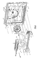
- FIG. 1 is an enlarged side elevation of an evaporator housing embodying the teachings of the present invention;
- FIG. 2 is a rear perspective view of the evaporator housing with parts broken away to better illustrate the interior of the housing;
- FIG. 3 is an exploded view showing the various components contained within the housing;
- FIG. 4 is a rear elevation of the front wall cover of the evaporator housing;
- FIG. 5 is an enlarged front perspective view of a cover used to cover the open face of a blower wheel enclosure contained within the housing;
- FIG 6 is a rear perspective view of the cover illustrated in Fig. 5;
- FIG. 7 is a front view of the cover illustrated in Fig. 4;
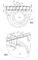
- FIG. 8 is an enlarged sectional view taken along lines 8-8 in Fig. 7 showing the vanes mounted with the outlet nozzle of the cover;
- FIG. 9 is an enlarged sectional view taken along lines 9-9 in Fig. 7; and,
- FIG. 10 is an enlarged partial view in perspective further illustrating the entrance to the outlet nozzle of the cover.
-
- Referring now to Figs. 1-3, there is illustrated the indoor section, generally referenced 10, of an air conditioning unit for delivering conditioned air to the interior of a mobile temperature controlled
container 11. As viewed in Fig. 3, the indoor section and the outdoor section of the air conditioning unit are both mounted upon aframe 13 that is secured to the container adjacent to the container's front wall 14. As will be described in greater detail below, the indoor section of the unit includes a housing 15 through which air drawn from the container is conditioned to either heat or cool the air and the conditioned air is then returned to the container to maintain the container at desired temperature levels. - The
indoor section 10 of the air conditioning unit includes a rectangularshaped frame 17 containing a pair ofopposed side walls bottom wall 20 and atop wall 21. The rear face of the frame is closed by securing the rear of the frame directly to onewall 23 of the container as shown in Fig. 1 or by bolting amounting plate 24 over the face of the frame, which, in turn, can be mounted upon a wall of the trailer which is preferably the front wall. The front of the frame is closed by means of a front wall that is generally referenced 25. - The front wall of the housing is preferably molded from a high strength plastic material having a low thermal conductivity so that the wall presents a barrier to the flow of heat into or out of the housing. The frame is also fabricated of a similar material so that the housing is a relatively well insulated structure. Two compartments are molded into the front wall of the indoor housing. The first is a
heat exchanger compartment 27 located in the lower part of the wall and the second is a blower wheel compartment that is located in the wall directly over the lower compartment. Both compartments open into the interior region of the frame. - The lower
heat exchanger compartment 27 has a rectangular-shaped bottom section 30 and an inwardly slantedtop section 31 that blends into the blower wheel compartment as illustrated in Fig. 3. The floor 32 of the heat exchanger compartment is in coplanar alignment with the bottom wall of theframe 17. Aheat exchanger 35 is mounted in a support bracket 36 (Fig. 3) and the assembly is placed inside the housing with a portion of the heat exchanger being located within the rectangular-shaped lower section of the heat exchanger compartment. The bottom wall of the frame contains anair inlet opening 39 that extends across the width of the frame beneath the heat exchanger through which return air from the container enters the housing. Although not shown, suitable duct work is provided for conducting return air from the container to the air inlet opening of the housing. - The blower wheel compartment includes a lower scroll-
shaped section 46 that communicates directly with a rectangular-shaped discharge section 42. Ablower wheel 43 is mounted for rotation upon ashaft 45 that passes into the scroll-shaped section 46 of the compartment. A portion of the scroll section of the compartment describes a spiral with the center of rotation of the spiral being coaxially aligned with the axis of the shaft. The shaft passes out of the compartment through the front wall and is coupled to a suitable drive (not shown) for turning the blower wheel at a desired speed. - The open side of the blower wheel compartment is closed by a
cover 50 which is shown in greater detail in Figs. 4-9. Threaded lugs 51-51 are molded into thefront wall 25 of the housing. The lugs are arranged to receive threaded fasteners 53-53 that are passed through clearance holes 54-54 in the cover to secure the cover in place over the side wall opening of the blower wheel compartment. - A gasket 55 (Fig. 3) is placed between the cover and the front wall of the housing to prevent air from passing therebetween.
- The cover includes a
circular opening 60 formed therein. The opening is axially aligned with the central axis of the blower wheel. A rectangularshaped nozzle 62 is also provided in the cover and, in assembly, is located adjacent to the discharge section of the blower wheel compartment. The nozzle extends outwardly from themain body 63 of the cover and is adapted to pass through thewall 23 of the container. The blower wheel is designed to draw return air into the indoor housing throughinlet 39 and then through theheat exchanger coil 35 wherein the air is conditioned. The air enters the blower through thecircular inlet 60 that has an inwardly directedlip 65 that converges from the inlet opening toward the blower wheel. The conditioned air enters the wheel through its hub and the impeller blades increase the velocity of the flow and discharge of air into the entrance of the nozzle through the discharge region of the blower wheel compartment. Thetop wall 67 and thebottom wall 68 of the nozzle converge from the entrance region toward the exit region to further increase the velocity of the flow. - The
nozzle 62 contains a series of flow deflector vanes generally referenced 70. Each vane is a Z-shaped member having alower flange 72 that is connected to anupper flange 73 by a generallyvertical web 75. Each lower flange contains anelongated detent 76 that is received in anelongated slot 77 formed in thebottom wall 68 of the nozzle. The upper flange of each deflector is similarly furnished with anelongated detent 80 that is received in anelongated slot 81 formed in thetop wall 67 of the nozzle. The opposed flanges are secured to the walls of the nozzle by screws 83-83. - The webs of each individual deflector are tuned by adjusting the contour of the web so that the flow is directed into the container and is optimized so that the air flow is uniformly distributed both vertically and horizontally across the container. The discharge flow, in addition, exhibits improved flow throw characteristics when compared to similar prior art systems.
- While the present invention has been particularly shown and described with reference to the preferred mode as illustrated in the drawing, it will be understood by one skilled in the art that various changes in detail may be effected therein without departing from the scope of the invention as defined by the claims.
Claims (16)
- An indoor section of or for a mobile temperature controlled container of an air conditioning unit of said indoor section including:a housing (15) that closes against one wall of said container and further includes a front wall that is opposed to said one wall of said container;a heat exchanger coil (35) mounted inside said housing (15);an open face compartment that extends inwardly from said front wall of the housing that has a scroll-shaped lower section (46) that is in fluid flow communication with an upper discharge section (42) of said compartment;a blower wheel (43) mounted for rotation inside the scroll-shaped section (46) of said compartment;a cover (50) mounted over the open face of said compartment, said cover having an air inlet opening (60) therein adjacent said blower wheel (43) through which conditioned supply air from the heat exchanger coil is drawn into the compartment; andwherein said cover (50) further includes an outlet nozzle (62) in fluid flow communication with the discharge section (42) of said enclosure through which air is discharged into said container through said one wall of said container.
- The indoor section of claim 1 wherein said outlet nozzle (62) is rectangular in form.
- The indoor section of claim 1 or 2 wherein the nozzle (62) contains defector elements (70) for controlling the flow of supply air into said trailer.
- The indoor section of claim 3 wherein said deflector elements (70) includes a series of spaced apart vanes (70) that are positioned to uniformly distribute supply air throughout the container.
- The indoor section of any preceding claim wherein said blower wheel (43) has an axis of rotation that is axially aligned along the center of the rotation of a spiral wall within the blower wheel compartment.
- The indoor section of claim 5 wherein said air inlet opening (60) in said cover (50) converges from a circular opening inwardly towards said blower wheel (43).
- The indoor section of claim 6 wherein said circular inlet opening (60) is about centered upon the axis of rotation of said blower wheel (43).
- The indoor section of any preceding claim wherein the inner wall surfaces of the spiral section of said enclosure describes a logarithmic spiral.
- The indoor section of any preceding claim wherein said nozzle (62) is integral with said cover (50).
- The indoor section of claim 9 wherein said outlet nozzle (62) contains a distal end that passes through the one wall (23) of the container (11).
- A cover (50) for closing the open side of an enclosure having a spiral shaped section (46) for rotatably housing a blower wheel (43) and a discharge area (42) into which the blower wheel discharges air, wherein said cover includes:means for securing said cover to said enclosure for closing said open side thereof;said cover having a first main body section that is positioned adjacent to said blower wheel (43) and a second nozzle section (62) that is positioned adjacent to said discharge area (42);said first section of the cover containing an air inlet opening (60) through which air is drawn into the enclosure.
- The cover of claim 11 wherein said nozzle section (62) extends outward from the front of said main body section of the cover and has a rectangular cross sectional area, and a series of stationary, vertically disposed vanes (70) are mounted between a top wall (67) and bottom wall (68) of the nozzle section in a spaced apart relationship across the nozzle.
- The cover of claim 12 wherein each vane (70) further includes a pair of parallel, spaced apart flanges (72, 73) that are co-joined by a vertically disposed web (75) and means (83) for securing a first flange to the top wall (67) of said nozzle section and a second flange to a bottom wall (68) of said nozzle section.
- The cover of claim 13 wherein the web (75) of each vane (70) is turned to optimize the throw and distribution of supply air discharged from the nozzle section.
- The cover of claim 13 or 14 wherein said flanges (72, 73) each contain an outwardly disposed elongated detent (76, 80) that is received in a slotted opening formed in the top and bottom walls (67, 68) of the nozzle (62).
- The cover of any of claims 11 to 15 wherein the nozzle section (62) has a top wall (67) and a bottom wall (68) that converge from an air entrance region to the nozzle section toward an air exit region of said nozzle section.
Applications Claiming Priority (2)
| Application Number | Priority Date | Filing Date | Title |
|---|---|---|---|
| US09/934,505 US6669555B2 (en) | 2001-08-22 | 2001-08-22 | Nozzle cover |
| US934505 | 2001-08-22 |
Publications (2)
| Publication Number | Publication Date |
|---|---|
| EP1310392A1 true EP1310392A1 (en) | 2003-05-14 |
| EP1310392B1 EP1310392B1 (en) | 2006-03-08 |
Family
ID=25465659
Family Applications (1)
| Application Number | Title | Priority Date | Filing Date |
|---|---|---|---|
| EP02255388A Expired - Lifetime EP1310392B1 (en) | 2001-08-22 | 2002-08-01 | Air conditioning unit for a transport container |
Country Status (3)
| Country | Link |
|---|---|
| US (1) | US6669555B2 (en) |
| EP (1) | EP1310392B1 (en) |
| DE (1) | DE60209651T2 (en) |
Cited By (1)
| Publication number | Priority date | Publication date | Assignee | Title |
|---|---|---|---|---|
| WO2006100576A1 (en) * | 2005-03-25 | 2006-09-28 | Ferrari S.P.A. | Forced air ventilation unit in a climate control system |
Families Citing this family (11)
| Publication number | Priority date | Publication date | Assignee | Title |
|---|---|---|---|---|
| DE102005028890C5 (en) * | 2005-06-22 | 2013-09-19 | Spheros Gmbh | Air-conditioning roof module |
| DE102007033548B4 (en) * | 2006-10-31 | 2021-03-04 | Siemens Healthcare Gmbh | Cooling module, technical device with a cooling module and method for internal cooling of a technical device |
| BRPI0721861A2 (en) * | 2007-07-24 | 2014-02-18 | Carrier Corp | TRAIL COOLING SYSTEMS |
| DE202011103765U1 (en) | 2010-08-10 | 2011-12-01 | Ebm-Papst St. Georgen Gmbh & Co. Kg | blower assembly |
| CN104520145B (en) * | 2012-06-19 | 2018-04-27 | 冷王公司 | Transport refrigeration bulkhead |
| JP6378935B2 (en) * | 2014-05-27 | 2018-08-22 | サンデンホールディングス株式会社 | Air conditioner for vehicles |
| DE102015118557A1 (en) | 2015-10-30 | 2017-05-04 | Ebm-Papst Mulfingen Gmbh & Co. Kg | rooftop air |
| EP3490827B1 (en) * | 2016-07-28 | 2021-05-12 | Carrier Corporation | Air supply system comprising a trailer, a refrigeration unit and an air supply nozzle |
| EP3686525A1 (en) * | 2019-01-25 | 2020-07-29 | Carrier Corporation | Self-venting refrigerant coil |
| CN111006369B (en) * | 2019-12-17 | 2021-11-30 | 广东美的暖通设备有限公司 | Transmission mechanism, indoor unit and air conditioner |
| CN120156259A (en) * | 2023-12-15 | 2025-06-17 | 开利公司 | Air diffusers for evaporators of transport refrigeration units |
Citations (3)
| Publication number | Priority date | Publication date | Assignee | Title |
|---|---|---|---|---|
| US3018642A (en) * | 1960-05-09 | 1962-01-30 | American Air Filter Co | Air conditioner |
| US3871188A (en) * | 1973-09-07 | 1975-03-18 | Thermo King Corp | Demountable transportation refrigeration unit |
| US4365484A (en) * | 1981-02-24 | 1982-12-28 | Carrier Corporation | Transport refrigeration machine |
Family Cites Families (7)
| Publication number | Priority date | Publication date | Assignee | Title |
|---|---|---|---|---|
| US3590218A (en) * | 1970-01-02 | 1971-06-29 | Emerson Electric Co | Wall mounted heater |
| US3877356A (en) * | 1972-09-05 | 1975-04-15 | Herbert F Bruns | Variable air distribution system |
| US3834453A (en) * | 1972-11-07 | 1974-09-10 | Tiem Inc Ab | Air conditioning unit |
| US4072187A (en) * | 1976-05-10 | 1978-02-07 | Advance Machine Corporation | Compact heating and cooling system |
| DE2902670A1 (en) * | 1978-02-01 | 1979-08-02 | Prl Soc | CONVECTION HEATER |
| US4644135A (en) * | 1983-08-29 | 1987-02-17 | The Marley Company | Wall mounted forced air electric heater |
| US6497112B1 (en) * | 2001-08-22 | 2002-12-24 | Carrier Corporation | Integrated pod scroll |
-
2001
- 2001-08-22 US US09/934,505 patent/US6669555B2/en not_active Expired - Lifetime
-
2002
- 2002-08-01 EP EP02255388A patent/EP1310392B1/en not_active Expired - Lifetime
- 2002-08-01 DE DE60209651T patent/DE60209651T2/en not_active Expired - Lifetime
Patent Citations (3)
| Publication number | Priority date | Publication date | Assignee | Title |
|---|---|---|---|---|
| US3018642A (en) * | 1960-05-09 | 1962-01-30 | American Air Filter Co | Air conditioner |
| US3871188A (en) * | 1973-09-07 | 1975-03-18 | Thermo King Corp | Demountable transportation refrigeration unit |
| US4365484A (en) * | 1981-02-24 | 1982-12-28 | Carrier Corporation | Transport refrigeration machine |
Cited By (1)
| Publication number | Priority date | Publication date | Assignee | Title |
|---|---|---|---|---|
| WO2006100576A1 (en) * | 2005-03-25 | 2006-09-28 | Ferrari S.P.A. | Forced air ventilation unit in a climate control system |
Also Published As
| Publication number | Publication date |
|---|---|
| EP1310392B1 (en) | 2006-03-08 |
| DE60209651T2 (en) | 2006-12-14 |
| DE60209651D1 (en) | 2006-05-04 |
| US6669555B2 (en) | 2003-12-30 |
| US20030037912A1 (en) | 2003-02-27 |
Similar Documents
| Publication | Publication Date | Title |
|---|---|---|
| US4926655A (en) | Air conditioner unit suitable for mounting on the roof of a vehicle | |
| US5916253A (en) | Compact trailer refrigeration unit | |
| CA2008665C (en) | Bus air conditioner suitable for mounting within the normal profile of a bus | |
| US6134909A (en) | Evaporator housing | |
| EP1310392B1 (en) | Air conditioning unit for a transport container | |
| US6105383A (en) | Evaporator unit for small bus | |
| CA2413667C (en) | Ceiling assembly for the ducted type of rvac | |
| US6161609A (en) | Flow control apparatus | |
| US5381672A (en) | Cabinet refrigeration system with cold air distributor | |
| KR960031910A (en) | Air conditioner | |
| US20100120345A1 (en) | Fresh air box | |
| KR20000028591A (en) | Compact air conditioner | |
| US5738492A (en) | Constant velocity air foil | |
| US3112623A (en) | Air conditioning enclosure | |
| US11971179B2 (en) | Air conditioner | |
| EP1285792B1 (en) | Air conditioning unit for a transport container | |
| US20210231320A1 (en) | An improved evaporative air cooler | |
| US5154066A (en) | Cooling a compressor and condenser of a refrigerator | |
| US5236393A (en) | Bypass damper in series-type ventilation fan | |
| US6718786B1 (en) | Coil housing design for a bus air conditioning unit | |
| US5588484A (en) | Refrigeration fan system | |
| US20070130980A1 (en) | Air Conditioner | |
| US4669534A (en) | Air conditioner | |
| WO1993008434A1 (en) | Monolithic refrigeration unit for refrigeration chambers and the like | |
| US20190351743A1 (en) | Compact rear vehicle hvac structure |
Legal Events
| Date | Code | Title | Description |
|---|---|---|---|
| PUAI | Public reference made under article 153(3) epc to a published international application that has entered the european phase |
Free format text: ORIGINAL CODE: 0009012 |
|
| 17P | Request for examination filed |
Effective date: 20030205 |
|
| AK | Designated contracting states |
Designated state(s): AT BE BG CH CY CZ DE DK EE ES FI FR GB GR IE IT LI LU MC NL PT SE SK TR |
|
| AX | Request for extension of the european patent |
Extension state: AL LT LV MK RO SI |
|
| 17Q | First examination report despatched |
Effective date: 20031022 |
|
| AKX | Designation fees paid |
Designated state(s): CZ DE FR IE |
|
| GRAP | Despatch of communication of intention to grant a patent |
Free format text: ORIGINAL CODE: EPIDOSNIGR1 |
|
| GRAS | Grant fee paid |
Free format text: ORIGINAL CODE: EPIDOSNIGR3 |
|
| GRAA | (expected) grant |
Free format text: ORIGINAL CODE: 0009210 |
|
| AK | Designated contracting states |
Kind code of ref document: B1 Designated state(s): CZ DE FR IE |
|
| REG | Reference to a national code |
Ref country code: IE Ref legal event code: FG4D |
|
| REF | Corresponds to: |
Ref document number: 60209651 Country of ref document: DE Date of ref document: 20060504 Kind code of ref document: P |
|
| ET | Fr: translation filed | ||
| RAP2 | Party data changed (patent owner data changed or rights of a patent transferred) |
Owner name: CARRIER CORPORATION |
|
| PLBE | No opposition filed within time limit |
Free format text: ORIGINAL CODE: 0009261 |
|
| STAA | Information on the status of an ep patent application or granted ep patent |
Free format text: STATUS: NO OPPOSITION FILED WITHIN TIME LIMIT |
|
| 26N | No opposition filed |
Effective date: 20061211 |
|
| PGFP | Annual fee paid to national office [announced via postgrant information from national office to epo] |
Ref country code: CZ Payment date: 20080709 Year of fee payment: 7 Ref country code: IE Payment date: 20080718 Year of fee payment: 7 |
|
| PG25 | Lapsed in a contracting state [announced via postgrant information from national office to epo] |
Ref country code: CZ Free format text: LAPSE BECAUSE OF NON-PAYMENT OF DUE FEES Effective date: 20090801 |
|
| PG25 | Lapsed in a contracting state [announced via postgrant information from national office to epo] |
Ref country code: IE Free format text: LAPSE BECAUSE OF NON-PAYMENT OF DUE FEES Effective date: 20090803 |
|
| REG | Reference to a national code |
Ref country code: FR Ref legal event code: PLFP Year of fee payment: 15 |
|
| REG | Reference to a national code |
Ref country code: DE Ref legal event code: R082 Ref document number: 60209651 Country of ref document: DE Representative=s name: SCHMITT-NILSON SCHRAUD WAIBEL WOHLFROM PATENTA, DE |
|
| REG | Reference to a national code |
Ref country code: FR Ref legal event code: PLFP Year of fee payment: 16 |
|
| REG | Reference to a national code |
Ref country code: FR Ref legal event code: PLFP Year of fee payment: 17 |
|
| PGFP | Annual fee paid to national office [announced via postgrant information from national office to epo] |
Ref country code: FR Payment date: 20210723 Year of fee payment: 20 |
|
| PGFP | Annual fee paid to national office [announced via postgrant information from national office to epo] |
Ref country code: DE Payment date: 20210720 Year of fee payment: 20 |
|
| REG | Reference to a national code |
Ref country code: DE Ref legal event code: R071 Ref document number: 60209651 Country of ref document: DE |