EP1310313A1 - Rotatable tool for chip removing machining - Google Patents
Rotatable tool for chip removing machining Download PDFInfo
- Publication number
- EP1310313A1 EP1310313A1 EP02025225A EP02025225A EP1310313A1 EP 1310313 A1 EP1310313 A1 EP 1310313A1 EP 02025225 A EP02025225 A EP 02025225A EP 02025225 A EP02025225 A EP 02025225A EP 1310313 A1 EP1310313 A1 EP 1310313A1
- Authority
- EP
- European Patent Office
- Prior art keywords
- sheath body
- cutting part
- guiding groove
- projections
- holder part
- Prior art date
- Legal status (The legal status is an assumption and is not a legal conclusion. Google has not performed a legal analysis and makes no representation as to the accuracy of the status listed.)
- Withdrawn
Links
- 238000003754 machining Methods 0.000 title claims abstract description 7
- 238000005520 cutting process Methods 0.000 claims abstract description 69
- 230000008878 coupling Effects 0.000 claims abstract description 4
- 238000010168 coupling process Methods 0.000 claims abstract description 4
- 238000005859 coupling reaction Methods 0.000 claims abstract description 4
- 239000000463 material Substances 0.000 claims description 8
- 230000007935 neutral effect Effects 0.000 claims description 8
- 238000005452 bending Methods 0.000 claims description 4
- 238000003780 insertion Methods 0.000 claims description 4
- 230000037431 insertion Effects 0.000 claims description 4
- 238000012546 transfer Methods 0.000 claims description 3
- 238000000605 extraction Methods 0.000 claims 2
- 210000000056 organ Anatomy 0.000 claims 1
- 238000005553 drilling Methods 0.000 description 6
- 229910000831 Steel Inorganic materials 0.000 description 4
- 239000010959 steel Substances 0.000 description 4
- 230000008901 benefit Effects 0.000 description 3
- 238000003801 milling Methods 0.000 description 3
- 238000004049 embossing Methods 0.000 description 2
- 230000003993 interaction Effects 0.000 description 2
- 230000033001 locomotion Effects 0.000 description 2
- 238000004519 manufacturing process Methods 0.000 description 2
- 230000007704 transition Effects 0.000 description 2
- 241000251221 Triakidae Species 0.000 description 1
- 230000009471 action Effects 0.000 description 1
- 230000004323 axial length Effects 0.000 description 1
- 230000005540 biological transmission Effects 0.000 description 1
- 230000015572 biosynthetic process Effects 0.000 description 1
- 230000001419 dependent effect Effects 0.000 description 1
- 238000013461 design Methods 0.000 description 1
- 230000000694 effects Effects 0.000 description 1
- 230000005489 elastic deformation Effects 0.000 description 1
- 238000000227 grinding Methods 0.000 description 1
- 239000011796 hollow space material Substances 0.000 description 1
- 230000007774 longterm Effects 0.000 description 1
- 239000002184 metal Substances 0.000 description 1
- 238000000034 method Methods 0.000 description 1
- 238000012986 modification Methods 0.000 description 1
- 230000004048 modification Effects 0.000 description 1
- 230000002441 reversible effect Effects 0.000 description 1
- 230000003313 weakening effect Effects 0.000 description 1
Images




Classifications
-
- B—PERFORMING OPERATIONS; TRANSPORTING
- B23—MACHINE TOOLS; METAL-WORKING NOT OTHERWISE PROVIDED FOR
- B23C—MILLING
- B23C5/00—Milling-cutters
- B23C5/16—Milling-cutters characterised by physical features other than shape
- B23C5/20—Milling-cutters characterised by physical features other than shape with removable cutter bits or teeth or cutting inserts
-
- B—PERFORMING OPERATIONS; TRANSPORTING
- B23—MACHINE TOOLS; METAL-WORKING NOT OTHERWISE PROVIDED FOR
- B23B—TURNING; BORING
- B23B51/00—Tools for drilling machines
- B23B51/02—Twist drills
-
- B—PERFORMING OPERATIONS; TRANSPORTING
- B23—MACHINE TOOLS; METAL-WORKING NOT OTHERWISE PROVIDED FOR
- B23B—TURNING; BORING
- B23B2251/00—Details of tools for drilling machines
- B23B2251/02—Connections between shanks and removable cutting heads
-
- Y—GENERAL TAGGING OF NEW TECHNOLOGICAL DEVELOPMENTS; GENERAL TAGGING OF CROSS-SECTIONAL TECHNOLOGIES SPANNING OVER SEVERAL SECTIONS OF THE IPC; TECHNICAL SUBJECTS COVERED BY FORMER USPC CROSS-REFERENCE ART COLLECTIONS [XRACs] AND DIGESTS
- Y10—TECHNICAL SUBJECTS COVERED BY FORMER USPC
- Y10S—TECHNICAL SUBJECTS COVERED BY FORMER USPC CROSS-REFERENCE ART COLLECTIONS [XRACs] AND DIGESTS
- Y10S408/00—Cutting by use of rotating axially moving tool
- Y10S408/713—Tool having detachable cutting edge
-
- Y—GENERAL TAGGING OF NEW TECHNOLOGICAL DEVELOPMENTS; GENERAL TAGGING OF CROSS-SECTIONAL TECHNOLOGIES SPANNING OVER SEVERAL SECTIONS OF THE IPC; TECHNICAL SUBJECTS COVERED BY FORMER USPC CROSS-REFERENCE ART COLLECTIONS [XRACs] AND DIGESTS
- Y10—TECHNICAL SUBJECTS COVERED BY FORMER USPC
- Y10T—TECHNICAL SUBJECTS COVERED BY FORMER US CLASSIFICATION
- Y10T408/00—Cutting by use of rotating axially moving tool
- Y10T408/78—Tool of specific diverse material
-
- Y—GENERAL TAGGING OF NEW TECHNOLOGICAL DEVELOPMENTS; GENERAL TAGGING OF CROSS-SECTIONAL TECHNOLOGIES SPANNING OVER SEVERAL SECTIONS OF THE IPC; TECHNICAL SUBJECTS COVERED BY FORMER USPC CROSS-REFERENCE ART COLLECTIONS [XRACs] AND DIGESTS
- Y10—TECHNICAL SUBJECTS COVERED BY FORMER USPC
- Y10T—TECHNICAL SUBJECTS COVERED BY FORMER US CLASSIFICATION
- Y10T408/00—Cutting by use of rotating axially moving tool
- Y10T408/89—Tool or Tool with support
- Y10T408/907—Tool or Tool with support including detailed shank
-
- Y—GENERAL TAGGING OF NEW TECHNOLOGICAL DEVELOPMENTS; GENERAL TAGGING OF CROSS-SECTIONAL TECHNOLOGIES SPANNING OVER SEVERAL SECTIONS OF THE IPC; TECHNICAL SUBJECTS COVERED BY FORMER USPC CROSS-REFERENCE ART COLLECTIONS [XRACs] AND DIGESTS
- Y10—TECHNICAL SUBJECTS COVERED BY FORMER USPC
- Y10T—TECHNICAL SUBJECTS COVERED BY FORMER US CLASSIFICATION
- Y10T408/00—Cutting by use of rotating axially moving tool
- Y10T408/89—Tool or Tool with support
- Y10T408/909—Having peripherally spaced cutting edges
- Y10T408/9095—Having peripherally spaced cutting edges with axially extending relief channel
- Y10T408/9097—Spiral channel
-
- Y—GENERAL TAGGING OF NEW TECHNOLOGICAL DEVELOPMENTS; GENERAL TAGGING OF CROSS-SECTIONAL TECHNOLOGIES SPANNING OVER SEVERAL SECTIONS OF THE IPC; TECHNICAL SUBJECTS COVERED BY FORMER USPC CROSS-REFERENCE ART COLLECTIONS [XRACs] AND DIGESTS
- Y10—TECHNICAL SUBJECTS COVERED BY FORMER USPC
- Y10T—TECHNICAL SUBJECTS COVERED BY FORMER US CLASSIFICATION
- Y10T408/00—Cutting by use of rotating axially moving tool
- Y10T408/89—Tool or Tool with support
- Y10T408/909—Having peripherally spaced cutting edges
- Y10T408/9098—Having peripherally spaced cutting edges with means to retain Tool to support
-
- Y—GENERAL TAGGING OF NEW TECHNOLOGICAL DEVELOPMENTS; GENERAL TAGGING OF CROSS-SECTIONAL TECHNOLOGIES SPANNING OVER SEVERAL SECTIONS OF THE IPC; TECHNICAL SUBJECTS COVERED BY FORMER USPC CROSS-REFERENCE ART COLLECTIONS [XRACs] AND DIGESTS
- Y10—TECHNICAL SUBJECTS COVERED BY FORMER USPC
- Y10T—TECHNICAL SUBJECTS COVERED BY FORMER US CLASSIFICATION
- Y10T408/00—Cutting by use of rotating axially moving tool
- Y10T408/89—Tool or Tool with support
- Y10T408/909—Having peripherally spaced cutting edges
- Y10T408/9098—Having peripherally spaced cutting edges with means to retain Tool to support
- Y10T408/90987—Wedge means
Definitions
- this invention relates to a rotatable tool intended for chip removing or chip forming machining, which comprises two parts, viz. a holder part, mountable in a machine and rotatable around a geometrical centre axis, as well as a replaceable cutting part, which is connectable to the holder part via a male/female coupling, which includes on the one hand a seat having a shape tapering in the direction axially forwards, formed in a front end of the holder part, and on the other hand a male member, protruding from a rear end of the cutting part, which like the seat has an axially tapering shape, whereby a slot is formed in the front end portion of the holder part, which separates two elastically deflectable or resilient projections the function of which is to clamp the male member of the cutting part in the seat, and whereby the cutting member in an area outside the male member features a rearwardly directed , surface for the transfer of axial forces, and which co-operates with
- Cutting tools of the type that makes use of a holder part or basic body, as well as a separate, replaceable cutting part may in practice be of strongly varying shapes and consist of, for instance, drilling tools, milling tools, such as endmills or slitting cutters, thread cutters, etc.
- the holder part usually consists of a long narrow, shank of a cylindrical basic shape. In modem machine tools, the holder parts are so sophisticated and expensive that for economical reasons they cannot be integrated with the cutting part, which constitutes the wearing part of the tool.
- the actual cutting part as a separate, detachable unit (by those skilled in the art usually denominated "loose top"), which may be replaced after being worn-out, while the expensive holder part may be used for a longer period of time (usually 10 to 20 exchanges).
- the loose top is entirely or partly manufactured from a hard, wear-resistant material, such as cemented carbide or the like, while the holder part is made of a material having a greater elasticity, e.g. steel.
- tools of the kind in question are primarily - though not necessarily - intended for machining of workpieces of metal.
- the male member on the cutting part consists of a genuinely conical pin that is axially movable in and out of a likewise conically shaped seat, which tapers off in the forward direction and opens axially in the front end of the holder part.
- the fact that the pin is conical and exclusively axially introducable in the seat means that the resilient projections have to be deflected substantially outwards in order to be able to receive the pin, a fact that, if at all practicable, means that the projections risk being exposed to plastic, and not only elastic deformation.
- a primary aim of the invention is to provide a cutting tool that may be realized not only in the form of a milling tool, but also other tools, such as drilling tools, whereby the resilient projections should not need to be deflected to such a large extent that they risk being exposed to plastic deformation.
- An additional aim is to provide a cutting tool, the geometry of which in the interface between the loose top and the holder part is of such a nature that the holder part is not exposed to appreciable wear in connection with the exchange of loose tops; something which in turn should vouch for the holder part preserving a good ability to centre and locate the individual loose top also after repeated exchanges of loose tops.
- Another aim of the invention is to provide a cutting tool that can transmit great torques between the holder part and the loose top, also in those cases where the same are formed with chip channels of the type that characterizes drilling tools.
- Yet an aim of the invention is to provide a cutting tool that enables simple mounting and dismounting of the loose top without the holder part necessarily needing to be removed from a machine.
- each one of the two parts should be able to be produced by means of simple machining operations and with a minimum of advanced grinding operations.
- An additional aim is to create a tool which can depend exclusively on elasticity in both the projections on the holder in order to clamp the cutting part, that is to say without having to rely on any screw or other tensioning device for this purpose.
- the invention also relates to a cutting part as such intended for the tool.
- a cutting part as such intended for the tool.
- the invention is based on the idea of forming the seat in the holder part in the form of a sideways or radially opening guiding groove and the male member on the cutting part as a sheath like body, which can be fed into and drawn out sideways relative to the holder part.
- the sheath body shall be formed with one or more external wedge surfaces which are angled in relation to the centre axis of the tool, said wedge surfaces being arranged to interact with an equivalent number of internal, angled wedge surfaces which limit the guiding groove
- the holder and cutting parts are to include interacting means to centre the cutting part in a predetermined position in relation to the guiding groove.
- the holder part is to include means for making possible bending of the projections in a direction away from each other in order to make it possible to mount respectively dismount the cutting part.
- a drilling tool is disclosed, the holder part or shank of which in the front end thereof features a recess defined by two projections for receipt of a cutting part or loose top. Furthermore, a narrow slot is formed in the front-end portion of the holder part with the purpose of enabling elastic deflection of the projections.
- the two projections are formed with inwardly turned flank surfaces, which may be resiliently pressed against contact surfaces on the sides of the loose top, more precisely thanks to wedge surfaces being pressed into a V slot in the rear end of the loose top. The wedging is guaranteed by means of an axial screw within the holder part.
- a disadvantage of said tool is, however, that the loose top as well as the holder part has to be manufactured to a very high dimensional accuracy. Another disadvantage is that the tool demands dismounting from the appurtenant machine in order to enable manipulation of the axial screw in connection with exchange of the loose top.
- a cutting tool is furthermore known from US 5 957 631 (see also DE 298 09 638 U1) said tool having a loose top that is clampable in a holder part formed with two resilient projections, the inherent elasticity of which is utilized in order to clamp the loose top.
- the loose top has to be manually turned between locking and releasing positions, something which on the one hand demands great force from the user, and on the other hand results in wear or a so-called embossing, which long-term impairs the ability of the holder part to centre loose tops following each other in an exact way.
- a rotary cutting tool is described in US 5 769 577 in which a dovetail coupling is used between two components of the tool, that is to say a holder part and a drill unit.
- the holder part does not however include any elastically bendable projections of the type which characterizes the tool according to the invention which is the subject of this document.
- the tool illustrated in fig 1-6 is in the form of a drill, which in the usual way includes a holder part or basic body generally designated 1, as well as a replaceable cutting part or loose top 2.
- the holder part 1 consists of a long narrow shank of a cylindrical basic shape, which in figs 1-3 is shown in a cut truncated state.
- the shank is in a suitable way mountable in a machine, e.g. a multi-operation machine, and has two helicoidal, cross-section-wise concavely curved chip channels 3.
- a seat 5 is formed in which a slot 6 mouths, which slot separates two elastically deflectable projections 7, 8.
- the loose top 2 is of a rotationally symmetrical basic shape so far that it has a circular outer contour shape in connection with a substantially cylindrical or rearwardly slightly conical envelope surface 10 as well as a conical surface 11, the tip of which being directed forwards.
- the loose top has a diameter that is somewhat larger than the diameter of the holder part 1.
- two concavely curved limiting surfaces 12 are formed that connect to the curved shape of the chip channels 3.
- cutting edges 13 are formed, which are shown schematically in the example in the form of edge lines between the cone surface 11 and the limiting surfaces 12.
- the loose top 2 has a male member, in its entirety designated 14, for engagement with the seat 5. On either side of the male member 14, there are thrust transmitting surfaces 15 for interaction with the surfaces 9 of the holder part.
- C designates a geometrical centre axis around which the composed tool is rotatable. Said centre axis C should be common for the holder part 1 and the loose top 2 if the loose top is exactly centred in relation to the holder part.
- the loose top 2 is made entirely or partly from cemented carbide or another wear-resistant material, while the holder part 1 is made of a material having a considerably greater elasticity, e.g. steel. Steel is preferable as a consequence of the inherent elasticity or flexibility thereof, which makes it possible to resiliently deflect the projections 7, 8 spaced-apart by the slot 6. Such deflection is guaranteed in the embodiment according to fig 1-6 by a clamping device in the form of a screw 16, the character of which will be described in detail below.
- the male member 14 is of a partially tapering shape in the axial direction.
- the seat 5 is partially tapering in the axial direction. Said axially tapering shape of the male member and the seat, respectively, implies that the male member can be drawn into the seat when the same is clamped by the projections 7, 8 being inwardly deflected by means of the screw 16.
- the male member 14 consists of a sheath-like body and the seat 5 of a radial, laterally open guiding groove into and out of which the sheath body is laterally - but in general not axially - movable.
- the sheath body 14 together with the guiding groove or holder part comprises means in order to centre the sheath body in a predetermined position along the guiding groove. Said means will be described in closer detail below.
- the male member 14 in the illustrated, preferred embodiment includes on one hand a cross-section-wise dovetail-shaped portion 17, and on the other hand a thickened neck portion 18 between the end surfaces 15 and the dovetail portion 17.
- the dovetail portion 17 is delimited on one hand by a rear end surface 19, and on the other hand by two wedge surfaces 20 extending forwards from the same, which wedge surfaces are inclined at an angle ⁇ to the centre axis C.
- Said two wedge surfaces 20 may advantageously be plane, although it is feasible per se to completely or partially design the same with a slightly curved, e.g. slightly concavely curved shape.
- the end surface 19 may be plane. However, alternatively, even the end surface may also be curved, e.g. convexly curved.
- the neck portion 18 is delimited on one hand by two opposite flank surfaces 21, which in the example are plane and mutually parallel, and on the other hand by two first transverse surfaces 22, which may be plane, extending inwards towards the wedge surfaces 20.
- the thrust-transmitting end surfaces 15 on both sides of the sheath body 14 in the example are plane and extend perpendicularly to the centre axis C. Further it should be pointed out that even the guiding groove 5 extends at a right angle to the centre axis and radially in relation to the same.
- the side limiting surfaces 20, 21 of the sheath body are symmetrical in relation to the centre line C, i.e. the plane and mutually parallel surfaces 21 are located at equally large radial distances from the centre line C.
- the wedge surfaces 20 are located at equally large distances from the centre axis and inclined at the same angle ⁇ to the centre axis.
- the angle ⁇ may per se vary most considerably, but should be within the range of 5-25°, suitably 10-20°. In the example, the angle ⁇ amounts to 15°.
- the guiding groove 5 is of a cross-section shape that generally - but not exactly - corresponds to the cross-section shape of the sheath body 14.
- an outer space in the guiding groove is defined by two internal side-limiting surfaces 23, which in the example are plane and mutually parallel. Said surfaces 23 are intended to interact with the flank surfaces 21 on the sheath body 14.
- a pair of second transverse surfaces 24 extend, which transform into two second wedge surfaces 25, which like the first wedge surfaces 20 are inclined and converge in the forward direction.
- Said two internal wedge surfaces define an inner space or bottom space in the guiding groove.
- the angle of inclination ⁇ of the internal wedge surfaces 25 may advantageously differentiate from the angle ⁇ , more precisely in such a way that the angle ( ⁇ is somewhat smaller than the angle ⁇ .
- the angle ⁇ may, for instance, be about 0,5-5°, suitably 1-2° smaller than the angle ⁇ . Because of the angle ⁇ being larger than the angle ⁇ , contact between the interacting pairs of wedge surfaces will be established as deeply as possible inside the guiding groove that is to say the points of contact between the wedge surfaces located in immediate proximity of the bottom of the guiding groove. More precisely, the rear portions of the wedge surfaces 20 and 25 will be brought to contact with each other at the same time as a diverging clearance is attained in the direction forward from the contact places.
- the two surfaces 9 on both sides of the guiding groove 5 are plane and extend perpendicularly to the centre axis C.
- fig 6 illustrates how the guiding groove 5 in the holder part 1 extends radially in a radial plane designated R 1 through the centre axis C.
- the sheath body 14 on the loose top 2 extends in an analogous radial plane R 2 .
- Secondary planes extending perpendicularly to the planes R 1 and R 2 and intersecting the centre axis C are designated S 1 and S 2 , respectively.
- the radial plane R 1 is common for the guiding groove 5 and the slot 6, i.e. the slot 6 extends parallel to the side limiting walls 23, 25 of the guiding groove.
- the guiding groove in the example according to fig 1-6 is open at the opposite ends thereof. In this way, the sheath body 14 may be inserted into the guiding groove from either side of the holder part, and be drawn out in an arbitrary direction, respectively.
- figs 1-3 illustrate how the means for centring the cutting part 2 in relation to the holder part 1 comprises a button head protrusion 26 formed in one of the parts (figs 1 and 3) and a countersink 27 (fig 2) in the other part.
- the button head protrusion 26 is formed on the end surface 19 of the sheath body 14.
- the button head protrusion 26 is of a rotationally symmetrical basic shape and is suitably - though not necessarily - placed at the centre of the end surface 19, i.e. in the point where the radial planes R 2 and S 2 intersect each other.
- the countersink 27 is recessed in a bottom surface 28 of the guiding groove 5.
- said bottom surface 28 is plane and transforms via concavely arched or rounded transition surfaces 29 into plane recess surfaces 30, which in turn connect to the internal wedge surfaces 25.
- the countersink 27 is of a rotationally symmetrical basic shape, whereby the countersink suitably - though not necessarily - is placed centrally along the bottom of the groove surface 28 so far that the centre of the countersink 27 coincides with the centre axis C.
- the rotationally symmetrical shape of the button head protrusion and the countersink, respectively, may vary.
- the button head protrusion 26 is delimited by on the one hand a plane end surface 31, and on the other hand a convexly curved, circumfering envelope surface 32.
- the countersink 27 is defined by a plane bottom surface 33 and a concavely curved, circumfering cup surface 34.
- the button head protrusion is shallower than the countersink so that the same cannot touch the bottom of the countersink, whereby the button head protrusion may have a somewhat larger diameter, e.g. a 0.05 mm larger diameter than the countersink.
- the contact between the surfaces 32, 34 at least theoretically will consist of a line contact, more precisely a circumfering circular line, when the button head protrusion engages the countersink. Because the slot 6 intersects the countersink, the countersink 27 limits the slot by two substantially semi-circular recesses in the bottom of the groove.
- the holder part 1 is shown in a tensionless state in which the two projections 7, 8 on each side of the slot 6 assume an exit or neutral position.
- the two surfaces 6A, 6B that define the slot are plane, the same being mutually parallel when the projections are in the neutral position.
- the slot 6 extends from the bottom surface of the groove 28 to a through hole 35 that facilitates the deflection of the projections.
- the axial length of the slot should amount to at least 0,8 ⁇ the diameter of the holder part 1, but may also advantageously be larger, e.g. within the range of 1-2 times the diameter.
- the projections 7, 8 may be deflected outwards as well as inwards (inwardly deflection is only possible as long as the loose top is not mounted), more precisely by means of the screw 16 serving as clamping device.
- the screw 16 intended for deflection of the projections is double acting in the manner described below.
- the screw includes a head 36 and a shank having a waist 37 that separates a male thread 38 from a smooth section 39, on the end of which the head is formed.
- the male thread 38 is in engagement with a female thread 40 in the branch 8, while the smooth section 39 is freely rotatable in a non-threaded bore 41 in the branch 7.
- a rider 42 or the like is applied on the waist 37.
- the pressure washer 42 When the male thread 38 is unscrewed from the female thread by rotation of the screw in the opposite direction, the pressure washer 42 will be pressed against the limiting surface 6B of the slot 6 and bring the two projections to be separated from each other, as is shown in fig 5.
- the deflection motions of the projections may in practice be highly limited. In drills having a diameter of, for instance, 16 mm, the slot 6 may have a width of 0.24 mm, whereby the deflection outwards of the projections from the neutral position amounts to 0.05 mm in the area of the bottom of the groove 28.
- the head 36 of the tightening screw 16 is housed in a countersink 43 in one side of the holder part. In other words, the screw does not protrude from the envelope surface of the holder part. It should also be pointed out that the screw 16 advantageously is radially positioned, i.e. located in the radial plane S 1 , and extends perpendicularly to the slot 6.
- the two projections 7, 8 are deflected outwards from each other (see fig 5) in the manner described previously by means of the tightening screw 16.
- the guiding groove 5 is widened so that the dovetail portion of the sheath body can be inserted without obstacle into the bottom space of the guiding groove, i.e. between the internal wedge surfaces 25.
- the sheath body may be located at a certain axial distance from the bottom of the groove. In this way, the plane end surface 31 of the button head protrusion 26 may slide along the bottom surface 28 of the groove without any resistance to insertion of the sheath body arising.
- the button head protrusion 26 When the button head protrusion 26 reaches the countersink 27, the same automatically engages the countersink and is centred in the same. When this is effected, the tightening screw 16 is tightened. In doing so, the two projections 7, 8 will be deflected inwards towards each other to the aforementioned neutral position. During this inwardly deflection of the projections, the sheath body will be drawn successively rearwards into the guiding groove by interaction between the pairs of wedge surfaces 20, 25. A wedge action simply arises, pulling the sheath body axially into the guiding groove with a certain force until the surfaces 15 of the loose top 2 have been pressed into close contact against the surfaces 9 of the holder body.
- the button head protrusion 26 is of course also pressed axially into the countersink 27 and centred in the radial planes R 1 and R 2 by the circumfering line contact that is established between the external envelope surface 32 of the button head protrusion and the internal cup surface 34 of the countersink. Due to the fact that the button head protrusion is shallower than the countersink, the plane end surface 31 of the button head protrusion will never come into contact with the plane bottom surface 33 of the countersink. As is seen in fig 4, neither the two transverse surfaces 22 of the neck portion 18 will come into contact with the two corresponding transverse surfaces 24 of the guiding groove. On the contrary, a clear play or gap 44 is maintained between said surfaces.
- the two external flank surfaces 21 of the neck portion 18 and the corresponding internal side limiting surfaces 23 in the guiding groove are pressed in close contact against each other.
- the transmission of torque is carried out between the holder part and the loose top essentially via said pair of surfaces 21, 23.
- the side limiting surfaces 23 are located at a comparatively large radial distance from the centre of the holder part. This means that the surfaces 23 receive a greater length and, thereby, improved surface abutment than if they would be situated closer to the centre of the holder part, where the part of the holder part defined between the chip channels 12 is thinner.
- the procedure is the reverse, i.e. the tightening screw 16 is unscrewed a distance from the appurtenant female thread, whereby the projections 7, 8 are deflected out to the outer end positions thereof in which the guiding groove is maximally widened.
- the centring button head protrusion 26 may be led out of the countersink 27 and the sheath body may be pulled out of the guiding groove towards an optional side.
- a tightening screw 16A is shown. Like the previously described tightening screw, said screw includes a shank and a head. At one end of the shank, a first male thread 46 is formed, which is either left-hand threaded or right-hand threaded. In the example, it is assumed that the same is left-hand threaded. At the opposite end of the shank, a second male thread 47 is formed having the opposite type of thread pitch, viz . right-hand threaded. The male thread 46 is in engagement with an analogous, i.e. left-hand threaded female thread 48 in one of the projections 7. The other male thread 47 is in turn in engagement with an analogous, i.e.
- the female thread 49 is formed in an insert ring 50 that is inserted into a widened hollow space 51 in the extension of the through bore 52 through which the screw extends. Following insertion into the space 51, the ring 50 is rigidly locked in relation to the branch 8, e.g. by means of a cotter (not shown).
- the recess 53 has a substantially half-circular shape in the example shown whereas the other recess 54 has a half-oval or shallow arched shape.
- the shape of the recesses and hence also that of the hole 55 can vary greatly within the scope of the invention. Theoretically it is therefore thinkable to form recess for an oval key in just the one end of the both the surfaces 6A, 6B. It should also be noted that the hole 55 is placed at a maximum distance from the hole 35 at the bottom of the slot 6. In this manner maximum leverage is obtained in conjunction with the turning of the key 56
- the axial support surfaces 9 (which form separate surfaces on either side of the guiding groove 5) are angled in relation to the centre axis of the holder part. More exactly the surfaces 9 are angled so that they form an obtuse angle the point of which is directed forwards. In the example the individual surface 9 is angled approximately 86° in relation to the centre axis, and as a result the obtuse angle mentioned will be 172.° This angle can of course vary somewhat both up and down. As can be seen in fig. 11 the interacting surfaces 15 on the rear of the cutting part 2 are angled at a corresponding obtuse angle, whereby the surfaces diverge in the rearwards direction.
- At least one of the two surfaces 9, 15 which interact in a pair have a cambered or convex arched shape. Arching of a surface in this manner can occur along the entire surface or just part of a surface. Provided however that only one of the two surfaces 9, 15 is to be arched and the other to be flat requires that the surface 9 be shaped with the arched part in the holder part 1 and in that the a shape of this sort lends itself to being formed by a simple means in the holder part which is manufactured in steel. By cambering or arching at least one of the surfaces in this manner the clearances 57 are achieved on either side of the contact point 58.
- the differences in level between the surfaces 28A, 28B can vary slightly and be of the order of for example 0.1 - 0.3 mm. But even so the difference in level leads to the formation of the shoulder 59 in connection to the right hand partial surface 28b. In the example the shoulder 59 is formed in this manner of the far part of the cup surface 34 which is connected to the partial surface 28B which is to be found furthest from the observer in fig. 9.
- the button head protrusion 26 When the sheath body 14 of the cutting body as described previously is slid into the guiding groove the button head protrusion 26 will come into contact with the shoulder 59, thereby the button head protrusion stops against the shoulder. In this manner the final mounting position of the sheath body and cutting part is determined in a distinct and exact way.
- the shoulder forms a means for centring the cutting part in relation to holder part.
- the sheath body in the embodiment in question can be slid into the guiding groove only from the one side of it, namely the end which is faced towards the observer in fig. 9. Furthermore it should be pointed out that one of the shoulders in the guiding groove can interact with other parts of the sheath body than just a central button head protrusion of the type described in order to centre the cutting part relative to the holder part. In this connection the shoulder can be positioned other than just in the bottom of the guiding groove
- a substantial advantage of the tool according to the invention is that the loose top may be clamped and centred in an exact way in the holder part by means of limited deflection motions of the two resilient projections of the holder part. In other words, the risk of plastic deformation in the holder part is minimised. Furthermore, the holder part is not exposed to inconvenient wear or embossing in connection with exchange of loose tops. In this way, it is guaranteed that the holder part can be used for a long time without losing its ability to centre the loose top in a predetermined and well-defined way. Furthermore, the tool can transmit large torques between the holder part and the loose top also in those cases when the tool consists of a drill having weakening chip channels. Furthermore, the loose top as well as the holder part may be manufactured in a simple and not very costly way by means of simple machining operations. The tool can also brought to fulfilment without any tensioning screw as is illustrated in figs. 9-11.
- the invention is not solely limited to the embodiment described above and illustrated in the drawings.
- the sheath body serving as a male member in the form of solely a dovetail-shaped material portion, i.e. without the particular neck portion that has been described above.
- the sheath body with an asymmetrical shape, e.g. having only one wedge surface interacting with a corresponding wedge surface in the guiding groove.
- the clamping device requisite for the deflection of the projections may be made in another way than in the form of one single double-acting screw.
- two screws may be arranged, one of which deflects the projections in the direction outwards and the other provides the projections with a tensile force in the direction inwards. It is also feasible to form a double-acting tightening screw in another way than the above described.
- the neck portion 18 of the sheath body 14 is shown with the same width as the outer space in the guiding groove 5, i.e. the distance between the flank surfaces 21 is equally large as the distance between the side limiting surfaces 23 when the projections 7, 8 are in their tensionless neutral position.
- the outer space of the guiding groove may be manufactured so that the radial distance between the surfaces 23 is 1/1000 to 1/100 shorter than the corresponding radial distance between the flank surfaces 21.
- limiting surfaces 6A, 6B on both sides of the slot 6 have been shown in the form of plane surfaces, the shape of the surfaces may be modified, for instance in such a way that the contour of the surfaces becomes slightly S-shaped.
Landscapes
- Engineering & Computer Science (AREA)
- Mechanical Engineering (AREA)
- Drilling Tools (AREA)
- Milling Processes (AREA)
- Cutting Tools, Boring Holders, And Turrets (AREA)
- Clamps And Clips (AREA)
Abstract
Description
- In a first aspect, this invention relates to a rotatable tool intended for chip removing or chip forming machining, which comprises two parts, viz. a holder part, mountable in a machine and rotatable around a geometrical centre axis, as well as a replaceable cutting part, which is connectable to the holder part via a male/female coupling, which includes on the one hand a seat having a shape tapering in the direction axially forwards, formed in a front end of the holder part, and on the other hand a male member, protruding from a rear end of the cutting part, which like the seat has an axially tapering shape, whereby a slot is formed in the front end portion of the holder part, which separates two elastically deflectable or resilient projections the function of which is to clamp the male member of the cutting part in the seat, and whereby the cutting member in an area outside the male member features a rearwardly directed , surface for the transfer of axial forces, and which co-operates with a surface for the transfer of axial forces on the forward end of the holder part.
- Cutting tools of the type that makes use of a holder part or basic body, as well as a separate, replaceable cutting part, may in practice be of strongly varying shapes and consist of, for instance, drilling tools, milling tools, such as endmills or slitting cutters, thread cutters, etc. The holder part usually consists of a long narrow, shank of a cylindrical basic shape. In modem machine tools, the holder parts are so sophisticated and expensive that for economical reasons they cannot be integrated with the cutting part, which constitutes the wearing part of the tool. In other words, it is profitable to manufacture the actual cutting part as a separate, detachable unit (by those skilled in the art usually denominated "loose top"), which may be replaced after being worn-out, while the expensive holder part may be used for a longer period of time (usually 10 to 20 exchanges). In practice, the loose top is entirely or partly manufactured from a hard, wear-resistant material, such as cemented carbide or the like, while the holder part is made of a material having a greater elasticity, e.g. steel. It should also be pointed out that tools of the kind in question are primarily - though not necessarily - intended for machining of workpieces of metal.
- A tool of the initially generally mentioned kind is previously known from
DE 3 230 688 A1, more precisely the embodiment that is illustrated in fig 2 in the specification. In this case, the male member on the cutting part consists of a genuinely conical pin that is axially movable in and out of a likewise conically shaped seat, which tapers off in the forward direction and opens axially in the front end of the holder part. The fact that the pin is conical and exclusively axially introducable in the seat means that the resilient projections have to be deflected substantially outwards in order to be able to receive the pin, a fact that, if at all practicable, means that the projections risk being exposed to plastic, and not only elastic deformation. The actual clamping of the male member in the seat occurs thanks to the fact that the projections bend inwards with the help of a tensioning screw, which is in engagement with a female thread in a transverse hole in one of the projections and can rotate freely in a bore in the other projection. Furthermore, said tool according toDE 3 230 688 A1 is only shown in the form of a milling tool, i.e. a tool that lacks chip channels of the type that characterizes drilling tools. Therefore, the object patented could not be successfully applied to drilling tools, in particular tools having small diameters, because the material between the seat and the individual chip channels would become very thin and weakened. - The present invention aims at obviating the above-mentioned drawbacks of the tool known from
DE 3 230 688 A1 and at providing an improved tool. Thus, a primary aim of the invention is to provide a cutting tool that may be realized not only in the form of a milling tool, but also other tools, such as drilling tools, whereby the resilient projections should not need to be deflected to such a large extent that they risk being exposed to plastic deformation. An additional aim is to provide a cutting tool, the geometry of which in the interface between the loose top and the holder part is of such a nature that the holder part is not exposed to appreciable wear in connection with the exchange of loose tops; something which in turn should vouch for the holder part preserving a good ability to centre and locate the individual loose top also after repeated exchanges of loose tops. Another aim of the invention is to provide a cutting tool that can transmit great torques between the holder part and the loose top, also in those cases where the same are formed with chip channels of the type that characterizes drilling tools. Yet an aim of the invention is to provide a cutting tool that enables simple mounting and dismounting of the loose top without the holder part necessarily needing to be removed from a machine. It is also an aim to provide a cutting tool, the two main parts of which, i.e. the loose top and the holder part can be separately mass-produced in a simple and cost-effective way while guaranteeing a good centring of the loose top. Among other things, each one of the two parts should be able to be produced by means of simple machining operations and with a minimum of advanced grinding operations. An additional aim is to create a tool which can depend exclusively on elasticity in both the projections on the holder in order to clamp the cutting part, that is to say without having to rely on any screw or other tensioning device for this purpose. - According to the invention, at least the primary aim is attained by the features given in the characterizing clause of
claim 1. Preferred embodiments of the invention are furthermore defined in the dependent claims 2-19. - In a second aspect, the invention also relates to a cutting part as such intended for the tool. Features of the cutting part are seen in claims 20-26.
- The invention is based on the idea of forming the seat in the holder part in the form of a sideways or radially opening guiding groove and the male member on the cutting part as a sheath like body, which can be fed into and drawn out sideways relative to the holder part. Thereby the sheath body shall be formed with one or more external wedge surfaces which are angled in relation to the centre axis of the tool, said wedge surfaces being arranged to interact with an equivalent number of internal, angled wedge surfaces which limit the guiding groove, in addition the holder and cutting parts are to include interacting means to centre the cutting part in a predetermined position in relation to the guiding groove. Furthermore the holder part is to include means for making possible bending of the projections in a direction away from each other in order to make it possible to mount respectively dismount the cutting part.
- It is possible within the framework of the invention to maintain the cutting part clamped only with the help of the inherent elasticity in both the elastic projections which delimit the seat in the holder part, or with the help of a special tensioning device which in practice can take the form of a screw.
- In US 5 904 455, a drilling tool is disclosed, the holder part or shank of which in the front end thereof features a recess defined by two projections for receipt of a cutting part or loose top. Furthermore, a narrow slot is formed in the front-end portion of the holder part with the purpose of enabling elastic deflection of the projections. The two projections are formed with inwardly turned flank surfaces, which may be resiliently pressed against contact surfaces on the sides of the loose top, more precisely thanks to wedge surfaces being pressed into a V slot in the rear end of the loose top. The wedging is guaranteed by means of an axial screw within the holder part. A disadvantage of said tool is, however, that the loose top as well as the holder part has to be manufactured to a very high dimensional accuracy. Another disadvantage is that the tool demands dismounting from the appurtenant machine in order to enable manipulation of the axial screw in connection with exchange of the loose top.
- A cutting tool is furthermore known from US 5 957 631 (see also DE 298 09 638 U1) said tool having a loose top that is clampable in a holder part formed with two resilient projections, the inherent elasticity of which is utilized in order to clamp the loose top. However, in this case, the loose top has to be manually turned between locking and releasing positions, something which on the one hand demands great force from the user, and on the other hand results in wear or a so-called embossing, which long-term impairs the ability of the holder part to centre loose tops following each other in an exact way.
- A rotary cutting tool is described in US 5 769 577 in which a dovetail coupling is used between two components of the tool, that is to say a holder part and a drill unit. In this case the holder part does not however include any elastically bendable projections of the type which characterizes the tool according to the invention which is the subject of this document.
- In the drawings:
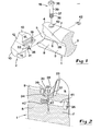
- Fig 1
- is a perspective exploded view showing the main parts in a cutting tool according to the invention, viz. a loose top and a partially shown holder part,
- Fig 2
- is an axially cut perspective view showing a front end of the holder part with a tightening screw included therein,
- Fig 3
- is a partly cut side view showing the holder part and the loose top in a separated state,
- Fig 4
- is a partially cut side view showing the loose top in a mounted and clamped state,
- Fig 5
- is a corresponding side view showing the loose top and the holder part during mounting/dismounting of the loose top,
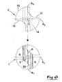
- Fig 6
- is an exploded view showing end views of the loose top and the holder part in a separated state, and
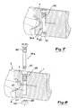
- Fig 7
- is a perspective cut view showing an alternative embodiment of a tightening screw for the tool, and
- Fig 8
- is an exploded view showing the tightening screw according to fig 7 separated from the tool.
- Fig 9
- is a perspective view showing a front end of a holder part according to an alternative embodiment of the tool according to the invention, whereby in connection to the holder part a key is shown said key to be used to bend the two projections in the holder part outwards,
- Fig 10
- is a side view of the holder part according to fig 9, and
- Fig 11
- is a further enlarged side view showing the holder part with a loose top mounted.
- The tool illustrated in fig 1-6 is in the form of a drill, which in the usual way includes a holder part or basic body generally designated 1, as well as a replaceable cutting part or
loose top 2. Theholder part 1 consists of a long narrow shank of a cylindrical basic shape, which in figs 1-3 is shown in a cut truncated state. The shank is in a suitable way mountable in a machine, e.g. a multi-operation machine, and has two helicoidal, cross-section-wise concavelycurved chip channels 3. In a front end designated 4 of theholder part 1, aseat 5 is formed in which aslot 6 mouths, which slot separates two elasticallydeflectable projections seat 5, there are thrust carryingsurfaces 9. - The
loose top 2 is of a rotationally symmetrical basic shape so far that it has a circular outer contour shape in connection with a substantially cylindrical or rearwardly slightlyconical envelope surface 10 as well as aconical surface 11, the tip of which being directed forwards. In general, the loose top has a diameter that is somewhat larger than the diameter of theholder part 1. In the envelope surface, two concavely curved limitingsurfaces 12 are formed that connect to the curved shape of thechip channels 3. In the front part of the loose top, cuttingedges 13 are formed, which are shown schematically in the example in the form of edge lines between thecone surface 11 and the limiting surfaces 12. At the rear end thereof, theloose top 2 has a male member, in its entirety designated 14, for engagement with theseat 5. On either side of themale member 14, there are thrust transmittingsurfaces 15 for interaction with thesurfaces 9 of the holder part. - In fig 3, C designates a geometrical centre axis around which the composed tool is rotatable. Said centre axis C should be common for the
holder part 1 and the loose top 2 if the loose top is exactly centred in relation to the holder part. - The
loose top 2 is made entirely or partly from cemented carbide or another wear-resistant material, while theholder part 1 is made of a material having a considerably greater elasticity, e.g. steel. Steel is preferable as a consequence of the inherent elasticity or flexibility thereof, which makes it possible to resiliently deflect theprojections slot 6. Such deflection is guaranteed in the embodiment according to fig 1-6 by a clamping device in the form of ascrew 16, the character of which will be described in detail below. - Furthermore, it should be pointed out that the
male member 14 is of a partially tapering shape in the axial direction. In an analogous way, theseat 5 is partially tapering in the axial direction. Said axially tapering shape of the male member and the seat, respectively, implies that the male member can be drawn into the seat when the same is clamped by theprojections screw 16. - As far as the shown tool has been described hitherto, the same is in all essentials previously known by
DE 3 230 688 A1. - Characteristic of the cutting tool according to the present invention is that the
male member 14 consists of a sheath-like body and theseat 5 of a radial, laterally open guiding groove into and out of which the sheath body is laterally - but in general not axially - movable. Another characteristic feature is that thesheath body 14 together with the guiding groove or holder part comprises means in order to centre the sheath body in a predetermined position along the guiding groove. Said means will be described in closer detail below. - As is seen in fig 3, the
male member 14 in the illustrated, preferred embodiment includes on one hand a cross-section-wise dovetail-shapedportion 17, and on the other hand a thickenedneck portion 18 between the end surfaces 15 and thedovetail portion 17. Thedovetail portion 17 is delimited on one hand by arear end surface 19, and on the other hand by twowedge surfaces 20 extending forwards from the same, which wedge surfaces are inclined at an angle α to the centre axis C. Said twowedge surfaces 20 may advantageously be plane, although it is feasible per se to completely or partially design the same with a slightly curved, e.g. slightly concavely curved shape. Theend surface 19 may be plane. However, alternatively, even the end surface may also be curved, e.g. convexly curved. - The
neck portion 18 is delimited on one hand by two opposite flank surfaces 21, which in the example are plane and mutually parallel, and on the other hand by two firsttransverse surfaces 22, which may be plane, extending inwards towards the wedge surfaces 20. In this connection, it should also be mentioned that the thrust-transmitting end surfaces 15 on both sides of thesheath body 14 in the example are plane and extend perpendicularly to the centre axis C. Further it should be pointed out that even the guidinggroove 5 extends at a right angle to the centre axis and radially in relation to the same. - Advantageously - though not necessarily - the
side limiting surfaces parallel surfaces 21 are located at equally large radial distances from the centre line C. In an analogous way, the wedge surfaces 20 are located at equally large distances from the centre axis and inclined at the same angle α to the centre axis. The angle α may per se vary most considerably, but should be within the range of 5-25°, suitably 10-20°. In the example, the angle α amounts to 15°. - The guiding
groove 5 is of a cross-section shape that generally - but not exactly - corresponds to the cross-section shape of thesheath body 14. Thus, an outer space in the guiding groove is defined by two internal side-limitingsurfaces 23, which in the example are plane and mutually parallel. Said surfaces 23 are intended to interact with the flank surfaces 21 on thesheath body 14. Inwards from theside limiting surfaces 23, a pair of secondtransverse surfaces 24 extend, which transform into two second wedge surfaces 25, which like the first wedge surfaces 20 are inclined and converge in the forward direction. Said two internal wedge surfaces define an inner space or bottom space in the guiding groove. The angle of inclination β of the internal wedge surfaces 25 may advantageously differentiate from the angle α, more precisely in such a way that the angle (β is somewhat smaller than the angle α. The angle β may, for instance, be about 0,5-5°, suitably 1-2° smaller than the angle α. Because of the angle α being larger than the angle β, contact between the interacting pairs of wedge surfaces will be established as deeply as possible inside the guiding groove that is to say the points of contact between the wedge surfaces located in immediate proximity of the bottom of the guiding groove. More precisely, the rear portions of the wedge surfaces 20 and 25 will be brought to contact with each other at the same time as a diverging clearance is attained in the direction forward from the contact places. - Like the
surfaces 15, the twosurfaces 9 on both sides of the guidinggroove 5 are plane and extend perpendicularly to the centre axis C. - Reference is now made to fig 6, which illustrates how the guiding
groove 5 in theholder part 1 extends radially in a radial plane designated R1 through the centre axis C. Thesheath body 14 on theloose top 2 extends in an analogous radial plane R2. Secondary planes extending perpendicularly to the planes R1 and R2 and intersecting the centre axis C are designated S1 and S2, respectively. - In the illustrated, preferred embodiment, the radial plane R1 is common for the guiding
groove 5 and theslot 6, i.e. theslot 6 extends parallel to theside limiting walls sheath body 14 may be inserted into the guiding groove from either side of the holder part, and be drawn out in an arbitrary direction, respectively. - Now, reference is again made to figs 1-3, which illustrate how the means for centring the cutting
part 2 in relation to theholder part 1 comprises abutton head protrusion 26 formed in one of the parts (figs 1 and 3) and a countersink 27 (fig 2) in the other part. In the preferred embodiment, thebutton head protrusion 26 is formed on theend surface 19 of thesheath body 14. Thebutton head protrusion 26 is of a rotationally symmetrical basic shape and is suitably - though not necessarily - placed at the centre of theend surface 19, i.e. in the point where the radial planes R2 and S2 intersect each other. - The
countersink 27 is recessed in abottom surface 28 of the guidinggroove 5. In the example, saidbottom surface 28 is plane and transforms via concavely arched or rounded transition surfaces 29 into plane recess surfaces 30, which in turn connect to the internal wedge surfaces 25. Like thebutton head protrusion 26, thecountersink 27 is of a rotationally symmetrical basic shape, whereby the countersink suitably - though not necessarily - is placed centrally along the bottom of thegroove surface 28 so far that the centre of thecountersink 27 coincides with the centre axis C. - The rotationally symmetrical shape of the button head protrusion and the countersink, respectively, may vary. In the example, the
button head protrusion 26 is delimited by on the one hand aplane end surface 31, and on the other hand a convexly curved, circumferingenvelope surface 32. In an analogous way, thecountersink 27 is defined by aplane bottom surface 33 and a concavely curved,circumfering cup surface 34. The button head protrusion is shallower than the countersink so that the same cannot touch the bottom of the countersink, whereby the button head protrusion may have a somewhat larger diameter, e.g. a 0.05 mm larger diameter than the countersink. In this way, it is guaranteed that the contact between thesurfaces slot 6 intersects the countersink, thecountersink 27 limits the slot by two substantially semi-circular recesses in the bottom of the groove. - In figs 1-3, the
holder part 1 is shown in a tensionless state in which the twoprojections slot 6 assume an exit or neutral position. In the example shown, the twosurfaces slot 6 extends from the bottom surface of thegroove 28 to a throughhole 35 that facilitates the deflection of the projections. The axial length of the slot should amount to at least 0,8 × the diameter of theholder part 1, but may also advantageously be larger, e.g. within the range of 1-2 times the diameter. From said neutral position, theprojections screw 16 serving as clamping device. - The
screw 16 intended for deflection of the projections is double acting in the manner described below. - As is seen in figs 1 and 2, the screw includes a
head 36 and a shank having awaist 37 that separates amale thread 38 from asmooth section 39, on the end of which the head is formed. Themale thread 38 is in engagement with afemale thread 40 in thebranch 8, while thesmooth section 39 is freely rotatable in anon-threaded bore 41 in thebranch 7. Via theslot 6, arider 42 or the like is applied on thewaist 37. When the screw is tightened, i.e. themale thread 38 is screwed in the direction inwards in thefemale thread 40, the pressure washer is 42 inactive, theprojections male thread 38 is unscrewed from the female thread by rotation of the screw in the opposite direction, thepressure washer 42 will be pressed against the limitingsurface 6B of theslot 6 and bring the two projections to be separated from each other, as is shown in fig 5. In this connection, it should be pointed out that the deflection motions of the projections may in practice be highly limited. In drills having a diameter of, for instance, 16 mm, theslot 6 may have a width of 0.24 mm, whereby the deflection outwards of the projections from the neutral position amounts to 0.05 mm in the area of the bottom of thegroove 28. - The
head 36 of the tighteningscrew 16 is housed in acountersink 43 in one side of the holder part. In other words, the screw does not protrude from the envelope surface of the holder part. It should also be pointed out that thescrew 16 advantageously is radially positioned, i.e. located in the radial plane S1, and extends perpendicularly to theslot 6. - When a
loose top 2 is to be connected to theholder part 1, the twoprojections screw 16. In this connection, the guidinggroove 5 is widened so that the dovetail portion of the sheath body can be inserted without obstacle into the bottom space of the guiding groove, i.e. between the internal wedge surfaces 25. In this connection, the sheath body may be located at a certain axial distance from the bottom of the groove. In this way, theplane end surface 31 of thebutton head protrusion 26 may slide along thebottom surface 28 of the groove without any resistance to insertion of the sheath body arising. When thebutton head protrusion 26 reaches thecountersink 27, the same automatically engages the countersink and is centred in the same. When this is effected, the tighteningscrew 16 is tightened. In doing so, the twoprojections surfaces 15 of the loose top 2 have been pressed into close contact against thesurfaces 9 of the holder body. Further tightening of the tightening screw when the projections have reached the neutral position entails that thesurfaces 23 of the projections are pressed into close contact against the flank surfaces 21 and clamp the sheath body with a considerable force during exact centring of the loose top, more precisely in the radial planes S1 and S2. - In connection with the tightening of the tightening screw, the
button head protrusion 26 is of course also pressed axially into thecountersink 27 and centred in the radial planes R1 and R2 by the circumfering line contact that is established between theexternal envelope surface 32 of the button head protrusion and theinternal cup surface 34 of the countersink. Due to the fact that the button head protrusion is shallower than the countersink, theplane end surface 31 of the button head protrusion will never come into contact with theplane bottom surface 33 of the countersink. As is seen in fig 4, neither the twotransverse surfaces 22 of theneck portion 18 will come into contact with the two correspondingtransverse surfaces 24 of the guiding groove. On the contrary, a clear play orgap 44 is maintained between said surfaces. Also between theplane end surface 19 of the sheath body and the tworecess surfaces 30, aplay 45 is maintained. However, as has been pointed out above, the two external flank surfaces 21 of theneck portion 18 and the corresponding internalside limiting surfaces 23 in the guiding groove are pressed in close contact against each other. In the illustrated embodiment, the transmission of torque is carried out between the holder part and the loose top essentially via said pair ofsurfaces side limiting surfaces 23 are located at a comparatively large radial distance from the centre of the holder part. This means that thesurfaces 23 receive a greater length and, thereby, improved surface abutment than if they would be situated closer to the centre of the holder part, where the part of the holder part defined between thechip channels 12 is thinner. - When a worn out loose top is to be removed, the procedure is the reverse, i.e. the tightening
screw 16 is unscrewed a distance from the appurtenant female thread, whereby theprojections button head protrusion 26 may be led out of thecountersink 27 and the sheath body may be pulled out of the guiding groove towards an optional side. - In figs 7 and 8, an alternative embodiment of a tightening
screw 16A is shown. Like the previously described tightening screw, said screw includes a shank and a head. At one end of the shank, a firstmale thread 46 is formed, which is either left-hand threaded or right-hand threaded. In the example, it is assumed that the same is left-hand threaded. At the opposite end of the shank, a secondmale thread 47 is formed having the opposite type of thread pitch, viz. right-hand threaded. Themale thread 46 is in engagement with an analogous, i.e. left-hand threadedfemale thread 48 in one of theprojections 7. The othermale thread 47 is in turn in engagement with an analogous, i.e. right-hand threadedfemale thread 49, which is included in theother branch 8. In this case, thefemale thread 49 is formed in aninsert ring 50 that is inserted into a widenedhollow space 51 in the extension of the throughbore 52 through which the screw extends. Following insertion into thespace 51, thering 50 is rigidly locked in relation to thebranch 8, e.g. by means of a cotter (not shown). - When the
screw 16A is brought to rotate in one of the directions of rotation, more precisely in such a way that themale thread 46 moves inwards in thefemale thread 48, the oppositemale thread 47 will work in the same way, i.e. move inwards in the appurtenantfemale thread 49. This means that the twoprojections male threads female threads projections - In the embodiments described above and those illustrated i figs. 1-8 bending both the projections outwards is achieved with the help of a tensioning device in-built in the holder and which is in the form of a screw which even has the function of actively tensioning both the projections against the loose topes male member sheath body. An alternative embodiment of a tool is shown in figs. 9-11 said tool differs fundamentally from that described above in that the holder part lacks all form of active tensioning device for the clamping of the loose top. Thus in the embodiment according to figs: 9-11 only the inherent elasticity of the projections is used primarily in order to hold fast the loose top. In order, in this connection, to make possible the outward flexing of the projections recesses 53, 54 are formed in both the
surfaces slot 6 and which together delimit anoval hole 55, which to advantage, but not necessarily, can be a through hole and extend at right angles to the centre axis of the tool. A separate key 56 with an oval cross section can be inserted in thishole 55, said key enables theprojections - The
recess 53 has a substantially half-circular shape in the example shown whereas theother recess 54 has a half-oval or shallow arched shape. The shape of the recesses and hence also that of thehole 55 can vary greatly within the scope of the invention. Theoretically it is therefore thinkable to form recess for an oval key in just the one end of the both thesurfaces hole 55 is placed at a maximum distance from thehole 35 at the bottom of theslot 6. In this manner maximum leverage is obtained in conjunction with the turning of the key 56 - A further difference between the embodiment according to figs. 9-11 and the embodiment described earlier is that the axial support surfaces 9 (which form separate surfaces on either side of the guiding groove 5) are angled in relation to the centre axis of the holder part. More exactly the
surfaces 9 are angled so that they form an obtuse angle the point of which is directed forwards. In the example theindividual surface 9 is angled approximately 86° in relation to the centre axis, and as a result the obtuse angle mentioned will be 172.° This angle can of course vary somewhat both up and down. As can be seen in fig. 11 the interacting surfaces 15 on the rear of the cuttingpart 2 are angled at a corresponding obtuse angle, whereby the surfaces diverge in the rearwards direction. The effect of the interacting pairs ofsurfaces rear surfaces 15 on the cutting part apply a thrust component onto thefront surfaces 9 on the holder part said thrust strives whilst the tool is in operation to bend theprojections - In accordance to the preferred embodiment of the invention at least one of the two
surfaces surfaces surface 9 be shaped with the arched part in theholder part 1 and in that the a shape of this sort lends itself to being formed by a simple means in the holder part which is manufactured in steel. By cambering or arching at least one of the surfaces in this manner theclearances 57 are achieved on either side of thecontact point 58. - In the embodiment according to figs. 9-11 the bottom of the guiding groove formed with two
partial surfaces recess 27 of the same type as has been described previously. In practice the differences in level between thesurfaces shoulder 59 in connection to the right hand partial surface 28b. In the example theshoulder 59 is formed in this manner of the far part of thecup surface 34 which is connected to thepartial surface 28B which is to be found furthest from the observer in fig. 9. - When the
sheath body 14 of the cutting body as described previously is slid into the guiding groove thebutton head protrusion 26 will come into contact with theshoulder 59, thereby the button head protrusion stops against the shoulder. In this manner the final mounting position of the sheath body and cutting part is determined in a distinct and exact way. In other words the shoulder forms a means for centring the cutting part in relation to holder part. - In this connection it should be pointed out that the sheath body in the embodiment in question can be slid into the guiding groove only from the one side of it, namely the end which is faced towards the observer in fig. 9. Furthermore it should be pointed out that one of the shoulders in the guiding groove can interact with other parts of the sheath body than just a central button head protrusion of the type described in order to centre the cutting part relative to the holder part. In this connection the shoulder can be positioned other than just in the bottom of the guiding groove
- A substantial advantage of the tool according to the invention is that the loose top may be clamped and centred in an exact way in the holder part by means of limited deflection motions of the two resilient projections of the holder part. In other words, the risk of plastic deformation in the holder part is minimised. Furthermore, the holder part is not exposed to inconvenient wear or embossing in connection with exchange of loose tops. In this way, it is guaranteed that the holder part can be used for a long time without losing its ability to centre the loose top in a predetermined and well-defined way. Furthermore, the tool can transmit large torques between the holder part and the loose top also in those cases when the tool consists of a drill having weakening chip channels. Furthermore, the loose top as well as the holder part may be manufactured in a simple and not very costly way by means of simple machining operations. The tool can also brought to fulfilment without any tensioning screw as is illustrated in figs. 9-11.
- The invention is not solely limited to the embodiment described above and illustrated in the drawings. Thus, it is feasible to manufacture the sheath body serving as a male member in the form of solely a dovetail-shaped material portion, i.e. without the particular neck portion that has been described above. Furthermore, it is feasible to make the sheath body with an asymmetrical shape, e.g. having only one wedge surface interacting with a corresponding wedge surface in the guiding groove. Furthermore, the clamping device requisite for the deflection of the projections may be made in another way than in the form of one single double-acting screw. Thus, instead of one screw, two screws may be arranged, one of which deflects the projections in the direction outwards and the other provides the projections with a tensile force in the direction inwards. It is also feasible to form a double-acting tightening screw in another way than the above described.
- In the example according to the drawings, the
neck portion 18 of thesheath body 14 is shown with the same width as the outer space in the guidinggroove 5, i.e. the distance between the flank surfaces 21 is equally large as the distance between theside limiting surfaces 23 when theprojections neck portion 18. Thus, the holder part may be manufactured so that the radial distance between thesurfaces 23 is 1/1000 to 1/100 shorter than the corresponding radial distance between the flank surfaces 21. In this way, already the inherent resilient force in the projections will provide the sheath body with a tensile force, irrespective of the fact that the tightening screw at tightening provides the sheath body with a considerable tensile force. This embodiment also improves the automatic centring of the sheath body in relation to the holder part. - Although the limiting
surfaces slot 6 have been shown in the form of plane surfaces, the shape of the surfaces may be modified, for instance in such a way that the contour of the surfaces becomes slightly S-shaped. -
- 1 =
- holder part
- 2 =
- cutting part
- 3 =
- chip channel
- 4 =
- end
- 5 =
- guiding groove
- 6 =
- slot
- 6A =
- slot surface
- 6B =
- slot surface
- 7 =
- branch
- 8 =
- branch
- 9 =
- thrust-carrying surface
- 10 =
- envelope surface
- 11 =
- cone surface
- 12 =
- channel limiting surface
- 13 =
- cutting edge
- 14 =
- sheath body
- 15 =
- thrust-transmitting surface
- 16 =
- tightening screw
- 16A=
- alternative tightening screw
- 17 =
- dovetail portion
- 18 =
- neck portion
- 19 =
- end surface
- 20 =
- wedge surface
- 21 =
- flank surface
- 22 =
- transverse surface
- 23 =
- side limiting surface
- 24 =
- transverse surface
- 25 =
- wedge surface
- 26 =
- button head protrusion
- 27 =
- countersink
- 28 =
- bottom of the groove surface
- 28a =
- partial bottom surface
- 28b =
- partial bottom surface
- 29 =
- curved transition surface
- 30 =
- recess surface
- 31 =
- button head protrusion end surface
- 32 =
- button head protrusion envelope surface
- 33 =
- bottom surface in countersink
- 34 =
- cup surface in countersink
- 35 =
- through hole
- 36 =
- screw head
- 37 =
- waist
- 38 =
- male thread
- 39 =
- smooth screw section
- 40 =
- female thread
- 41 =
- bore
- 42 =
- pressure washer
- 43 =
- countersink for screw head
- 44 =
- play
- 45 =
- play
- 46 =
- left male thread
- 47 =
- right male thread
- 48 =
- left female thread
- 49 =
- right female thread
- 50 =
- insert ring
- 51 =
- ring space
- 52 =
- bore
- 53 =
- recess
- 54 =
- recess
- 55 =
- hole
- 56 =
- key
- 57 =
- clearance
- 58 =
- point of contact
- 59 =
- shoulder
Claims (26)
- Rotatable tool for chip removing machining comprising two parts, viz. a holder part (1), mountable in a machine and rotatable around a geometrical centre axis (C), as well as a replaceable cutting part (2), which is rigidly connectable to the holder part via a male/female coupling, which includes on the one hand a seat (5) having a tapering shape in the direction axially forwards and formed in a front end (4) of the holder part, and on the other hand a male member (14) protruding from a rear end of the cutting part (2), which like the seat (5) has an axially tapering shape, whereby a slot (6) is formed in the front end portion of the holder part, which slot separates two elastically deflectable or resilient projections (7, 8) the function of which is to clamp the male member (14) of the cutting part in the seat (5), whereby the cutting part (2) in an area outside the male organ (14) features a rearwardly directed axial thrust transmitting surface (15), which interacts with an axial thrust absorbing surface (9) on the holders front end, characterized in, that the male member on the cutting part (2) consists of a sheath-like body (14) and the seat in the holder part (1) of a radial, laterally open guiding groove (5) into and out of which the sheath body is laterally - but not axially - movable, whereby at least one external, substantially plane wedge surface (20) on the sheath body, inclined in relation to the centre axis (C), is arranged to interact with an internal, inclined wedge surface (25) that defines the guiding groove, and that interacting means (26, 27, 59) are included in the holder (1) and cutting (2) parts in order to locate the sheath body in a predetermined position along the guiding groove and hence centre the cutting part , and that the holder includes means (16, 53, 54) to make possible the bending of the projections (7, 8) in a direction away from each other.
- Tool according to claim 1, characterized in, that the sheath body (14), entirely or partly, consists of a dovetail-shaped material portion (17) of a genuinely dovetail-like cross-section shape perpendicularly to a radial plane (R2) through the cutting part so far that two opposite, external wedge surfaces (20) are inclined at one and the same angle (α) to said radial plane.
- Tool according to claim 1 or 2, characterized in, that opposite, internal side limiting surfaces (23, 25) of the guiding groove are of a symmetrical shape on each side of a central radial plane (R1) through the holder part (1), and the analogous external side limiting surfaces (21, 20) of the sheath body (14) being of a symmetrical shape on each side of a central radial plane (R2) through the cutting part (2).
- Tool according to claim 2 or 3, characterized in, that two internal wedge surfaces (25) defining the guiding groove (5), which wedge surfaces interact with the external wedge surfaces (20) of the sheath body (14), are inclined at one and the same angle (β), which however is smaller than the angle of inclination (α) of the external wedge surfaces of the sheath body in order to bring about contact between the wedge surfaces (20, 25) deepest possible inside the guiding groove, whereby a clearance between the portions of the wedge surfaces distanced from the contact places is obtained.
- Tool according to any one of the preceding claims, characterized in, that a pair of axial thrust transmitting rear surfaces (15) on the cutting part and a pair of interacting axial thrust absorbing forward surfaces (9) on the holder part are both angled in relation to the centre axis (C) of the holder part, more exactly angled in an obtuse angle the point of which is directed forwards, whereby the rear surfaces on the cutting part submit the forward surfaces on the holder to force components which, when the tool is in operation, strive to bend the projections (7, 8) inwards leading to improved clamping of the sheath body (14).
- Tool according to claim 5, characterized in, that at least the one end of both the surfaces (9, 15) which interact in pairs has the form of a completely or partially convexed arch in order to create one or several clearances (57) alongside the points of contact (58).
- Tool according to any one of the claims 2-6, characterized in, that a thickened neck portion (18) is formed between the thrust transmitting surface (15) of the cutting part (2) and a cross-section-wise dovetail-shaped portion (17) of the sheath body (14), which neck portion is delimited by on one hand two opposite flank surfaces (21) that are plane and mutually parallel, and on the other hand two first transverse surfaces (22) extending inwards towards the wedge surfaces of the dovetail portion, which transverse surfaces are always separated via gaps (44) from two analogous, second transverse surfaces (24), which extend inwards from two mutually parallel surfaces (23), which form internal side limiting surfaces for the guiding groove and which are pressable against the flank surfaces (21) of the sheath body during clamping of the cutting part in order to transfer torque from the holder part to the cutting part .
- Tool according to any one of the preceding claims, characterized in, that the guiding groove (5) is open at opposite ends in order to permit insertion and extraction, respectively, of the sheath body (14) from optional side of the holder part (1).
- Tool according to any one of the proceeding claims, characterized in, that the guiding groove (5) and the slot (6) are located in a common radial plane (R1).
- Tool according to any one of the preceding claims, characterized in, that said means for centring the cutting part (2) in relation to the holder part (1) comprises a button head protrusion (26) formed in one of the parts for engagement with a countersink (27) in the other part.
- Tool according to claim 10, characterized in, that the button head protrusion (26) is located on a rearwardly directed end surface (19) of the sheath body (14), while the countersink (27) is formed in a bottom (28) in the guiding groove (5), whereby the button head protrusion is on the one hand freely movable along the bottom of the groove when the projections (7, 8) are separated in order to permit insertion and extraction of the sheath body, but are on the other hand pressed axially into the countersink when the projections are deflected inwards towards each other in connection with the clamping of the sheath body.
- Tool according to claim 10 or 11, characterized in, that the button head protrusion (26) is of a rotationally symmetrical basic shape and is shallower than the countersink (27) in order not to touch the bottom in the same.
- Tool according to claim 12, characterized in, that the contact between an external envelope surface (33) of the button head protrusion (26) and an internal limiting surface (34) in the countersink (27) is in the form of a line contact along a circumfering circular line.
- Tool according to any one of claims 10-13, characterized in, that the button head protrusion (26) and the countersink (27) are centrally placed on their respective parts.
- Tool according to any one of the preceding claims, characterized in, that the said means of centering the cutting part (2) relative to the holder part (1) includes a shoulder (59) linked to the guiding groove (5) against which a part of the sheath body (14) can be pressed in order to determine the position of the sheath body along the guiding groove, whereby the sheath body can be slid into the guiding groove from one end or the other.
- Tool according to any one of the preceding claims, characterized in, that a tensioning device consisting of a double-acting screw (16, 16A) which is arranged in the holding part (1), said device extends between the projections (7, 8) while bridging the slot (6), and which has the purpose of deflecting the projections on the one hand outwards from a tensionless neutral position with the purpose of broadening the space between the projections in connection with mounting and dismounting of the cutting part, and on the other hand inwards towards each other with the purpose of clamping the sheath body.
- Tool according to claim 16, characterized in, that the screw (16) comprises a head (36) and a shank having a waist (37), which separates a male thread (38) from a smooth section (39) on the end of which the head (36) is formed, whereby the male thread (38) is in engagement with a female thread (40) in a first branch (8) and the smooth section (39) is freely rotatable in a bore (41) in the second branch (7), and that a pressure washer (42) is applied on the waist (37) via the gap (6) between the projections, whereby the pressure washer on screwing of the screw in the direction out of the female thread in said first projection is pressed against the second projection during distancing of the projections from each other.
- Tool according to claim 16, characterized in, that the screw (16A) at one end thereof has a left-hand threaded male thread (46), which is in engagement with an analogous female thread (48) in one of the projections (7), and at the opposite end thereof has a right-hand threaded male thread (47), which is in engagement with an analogous female thread (49) included in the other branch (8).
- Cutting part according to any one of claims 1-15, characterized in, that said means to enable the bending of the projections (7, 8) outwards consists of at least one recess (53, 54) in a surface (6A, 6B) which limits a slot (6), whereby a separate key (56) with an oval cross-section can be inserted into the recess in order that it can, when turned, force apart said projections.
- Cutting part for tools according to any one of the preceding claims, including a male member (14) having an axially tapering shape protruding from a rear end and two rearwardly directed axial thrust transferring surfaces (15) in an area outside the male member (14), characterized in, that the male member consists of a sheath-like body (14) having a wedge surface (20) inclined in relation to a centre axis (C) and intended to interact with an internal, substantially plane and inclined wedge surface (25) that defines a guiding groove (5) in a holder part (1) included in the tool, and that the sheath body comprises means (26) for localizing the same in a predetermined position and thereby centring the cutting part in relation to the tool holder.
- Cutting part according to claim 20, characterized in, that the sheath body (14) entirely or partly consists of a dovetail-shaped material portion (17), which is of genuinely dovetail-like cross-section shape perpendicularly to a radial plane (R2) through the cutting part so far that two opposite, external wedge surfaces (20) are inclined at one and the same angle (α) to said radial plane.
- Cutting part according to claim 20 or 21, characterized in, that the opposite, external side limiting surfaces (21, 20) of the sheath body are of a symmetrical shape on each side of a central radial plane (R2) through the cutting part.
- Cutting part according to any one of claims 20-22, characterized in, that the rearwardly directed thrust transmitting surfaces (15) are V-shaped angled in an obtuse angle and divergent in the rearwards direction.
- Cutting part according to claims 20 and 21, characterized in, that a thickened neck portion (18) is formed between said thrust transmitting surface (15) and a cross-section-wise dovetail-shaped portion (17) of the sheath body (14), which neck portion is delimited by on one hand two opposite flank surfaces (21) which are mutually parallel, and on the other hand two first transverse surfaces (22) which extending inwards towards the wedge surfaces of the dovetail portion.
- Cutting part according to any one of claims 20-24, characterized in, that said means for centring the cutting part (2) in relation to the holder part (1) comprises a button head protrusion (26), which is located on a rearwardly directed end surface (19) of the sheath body (14).
- Cutting part according to claim 25, characterized in, that the button head protrusion (26) is of a rotationally symmetrical basic shape and is centrally positioned on the end surface (19) of the sheath body.
Applications Claiming Priority (2)
| Application Number | Priority Date | Filing Date | Title |
|---|---|---|---|
| SE0103752A SE0103752L (en) | 2001-11-13 | 2001-11-13 | Rotatable tool for chip separating machining and cutting part herewith |
| SE0103752 | 2001-11-13 |
Publications (1)
| Publication Number | Publication Date |
|---|---|
| EP1310313A1 true EP1310313A1 (en) | 2003-05-14 |
Family
ID=20285944
Family Applications (1)
| Application Number | Title | Priority Date | Filing Date |
|---|---|---|---|
| EP02025225A Withdrawn EP1310313A1 (en) | 2001-11-13 | 2002-11-12 | Rotatable tool for chip removing machining |
Country Status (7)
| Country | Link |
|---|---|
| US (1) | US6899495B2 (en) |
| EP (1) | EP1310313A1 (en) |
| JP (1) | JP4523226B2 (en) |
| KR (1) | KR100962458B1 (en) |
| CN (1) | CN100406175C (en) |
| SE (1) | SE0103752L (en) |
| WO (1) | WO2003041898A1 (en) |
Cited By (7)
| Publication number | Priority date | Publication date | Assignee | Title |
|---|---|---|---|---|
| WO2004067213A1 (en) * | 2003-01-28 | 2004-08-12 | Sandvik Intellectual Property Ab | Tool coupling for rotary tools |
| EP1555075A1 (en) * | 2004-01-14 | 2005-07-20 | Sandvik Aktiebolag | Rotatable tool for chip removing machining |
| EP1588790A3 (en) * | 2004-04-20 | 2009-04-01 | Sandvik AB | Rotatable tool for chip removing machining |
| WO2009129792A2 (en) | 2008-04-25 | 2009-10-29 | Gühring Ohg | Rotary-driven tool for cutting machining with a cutting body |
| CN101035642B (en) * | 2004-10-05 | 2010-10-06 | 山高刀具公司 | Tools with non-circular connection ends |
| EP2266734A1 (en) * | 2009-06-23 | 2010-12-29 | Sandvik Intellectual Property AB | A rotatable tool for chip removing machining as well as a loose top and a basic body therefor |
| EP3442735B1 (en) | 2016-04-12 | 2023-09-20 | Iscar Ltd. | Replaceable face-milling head with integrally formed threaded shank-connector |
Families Citing this family (49)
| Publication number | Priority date | Publication date | Assignee | Title |
|---|---|---|---|---|
| US20030039523A1 (en) * | 2001-07-13 | 2003-02-27 | Kemmer Hartmetallwerkzeuge Gmbh | Drilling or boring tool |
| DE10314889A1 (en) * | 2003-04-01 | 2004-10-14 | Komet Group Holding Gmbh | Tool for machine tools |
| SE0301456D0 (en) * | 2003-05-20 | 2003-05-20 | Sandvik Ab | An edge-bearing drill body, and a method of manufacturing and drilling tool comprising such drill body |
| SE526676C2 (en) * | 2003-05-20 | 2005-10-25 | Sandvik Intellectual Property | Egg-bearing drill body for long-hole drilling with edges made in one piece with the drill body |
| DE10353514A1 (en) | 2003-11-14 | 2005-06-23 | Heule, Ulf | Drilling plate with clamping attachment in a base body |
| USD519532S1 (en) * | 2004-04-02 | 2006-04-25 | Seco Tools Ab | Tip for an end milling cutter |
| IL162147A (en) * | 2004-05-24 | 2008-03-20 | Gil Hecht | Drill with releasably mounted cutting head |
| US20060024140A1 (en) * | 2004-07-30 | 2006-02-02 | Wolff Edward C | Removable tap chasers and tap systems including the same |
| US7309196B2 (en) * | 2004-10-05 | 2007-12-18 | Kennametal Inc. | Modular drill |
| IL164888A (en) * | 2004-10-28 | 2009-07-20 | Iscar Ltd | Cutting tool assembly and cutting head therefor |
| JP4747282B2 (en) * | 2005-03-29 | 2011-08-17 | 三菱マテリアル株式会社 | Insert removable drill |
| SE528255C2 (en) * | 2005-05-02 | 2006-10-03 | Sandvik Intellectual Property | Tools and removable body for chip separating machining tools with ridge and groove-shaped coupling means |
| US8637127B2 (en) | 2005-06-27 | 2014-01-28 | Kennametal Inc. | Composite article with coolant channels and tool fabrication method |
| US7687156B2 (en) | 2005-08-18 | 2010-03-30 | Tdy Industries, Inc. | Composite cutting inserts and methods of making the same |
| JP2009535536A (en) | 2006-04-27 | 2009-10-01 | ティーディーワイ・インダストリーズ・インコーポレーテッド | Modular fixed cutter boring bit, modular fixed cutter boring bit body and related method |
| WO2008051588A2 (en) | 2006-10-25 | 2008-05-02 | Tdy Industries, Inc. | Articles having improved resistance to thermal cracking |
| IL181295A (en) | 2007-02-12 | 2011-07-31 | Iscar Ltd | Tool with releasably mounted self-clamping cutting head |
| IL181296A0 (en) * | 2007-02-12 | 2007-07-04 | Iscar Ltd | Tool with releasably mounted self-clamping cutting head |
| US7846551B2 (en) | 2007-03-16 | 2010-12-07 | Tdy Industries, Inc. | Composite articles |
| DE102007024184A1 (en) * | 2007-05-24 | 2008-11-27 | Kennametal Inc. | Drills and methods for drilling |
| US8391561B2 (en) * | 2007-07-03 | 2013-03-05 | G-coder Systems AB | Pre tension monitoring solution |
| CN102112642B (en) | 2008-06-02 | 2013-11-06 | Tdy工业有限责任公司 | Cemented carbide-metallic alloy composites |
| US8790439B2 (en) | 2008-06-02 | 2014-07-29 | Kennametal Inc. | Composite sintered powder metal articles |
| US8322465B2 (en) | 2008-08-22 | 2012-12-04 | TDY Industries, LLC | Earth-boring bit parts including hybrid cemented carbides and methods of making the same |
| US8025112B2 (en) | 2008-08-22 | 2011-09-27 | Tdy Industries, Inc. | Earth-boring bits and other parts including cemented carbide |
| US8272816B2 (en) | 2009-05-12 | 2012-09-25 | TDY Industries, LLC | Composite cemented carbide rotary cutting tools and rotary cutting tool blanks |
| SE533853C2 (en) * | 2009-06-23 | 2011-02-08 | Sandvik Intellectual Property | Drilling tools for chip separating machining and release stop for this |
| SE533850C2 (en) * | 2009-06-23 | 2011-02-08 | Sandvik Intellectual Property | Loop stop type drilling tools |
| US8308096B2 (en) | 2009-07-14 | 2012-11-13 | TDY Industries, LLC | Reinforced roll and method of making same |
| WO2011021275A1 (en) * | 2009-08-18 | 2011-02-24 | オーエスジー株式会社 | Throw-away rotary tool |
| US9643236B2 (en) | 2009-11-11 | 2017-05-09 | Landis Solutions Llc | Thread rolling die and method of making same |
| SE534648C2 (en) * | 2010-03-26 | 2011-11-08 | Sandvik Intellectual Property | Rotatable tool for chip separating machining as well as loose stop and basic body for this |
| CN101879621B (en) * | 2010-07-05 | 2011-12-07 | 株洲钻石切削刀具股份有限公司 | Drilling processing cutting tool |
| CN101856735B (en) * | 2010-07-05 | 2012-01-18 | 株洲钻石切削刀具股份有限公司 | Drilling cutter |
| US8800848B2 (en) | 2011-08-31 | 2014-08-12 | Kennametal Inc. | Methods of forming wear resistant layers on metallic surfaces |
| US9016406B2 (en) | 2011-09-22 | 2015-04-28 | Kennametal Inc. | Cutting inserts for earth-boring bits |
| US9073129B2 (en) | 2012-03-22 | 2015-07-07 | Kennametal Inc | Cutting tool having replaceable cutting insert and replaceable cutting insert therefore |
| US8992141B2 (en) * | 2012-04-04 | 2015-03-31 | Iscar, Ltd. | Cutting head having resilient male coupling member for cutting tool and method of assembly thereof |
| CN102896479A (en) * | 2012-09-17 | 2013-01-30 | 苏茂均 | Method for manufacturing drill bit with cutting tool bit replaceable and product thereof |
| US9108251B2 (en) | 2012-12-05 | 2015-08-18 | Kennametal Inc. | Cutting tool having replaceable cutting tip, a replaceable cutting tip therefore and a method of securing a replaceable cutting tip |
| USD734790S1 (en) * | 2013-06-12 | 2015-07-21 | Element Six (Production) (Pty) Ltd | Drill bit tip |
| CN103331474A (en) * | 2013-06-30 | 2013-10-02 | 北京迪蒙集智科技有限公司 | Tip-interchangeable cylindrical milling cutter |
| CN103341657A (en) * | 2013-06-30 | 2013-10-09 | 北京迪蒙集智科技有限公司 | Twist drill with replaceable drill tip |
| DE102015106082A1 (en) * | 2014-04-24 | 2015-10-29 | Kennametal India Ltd. | Cutting tool with replaceable cutting insert and inclined fasteners |
| JP6769009B2 (en) * | 2015-11-16 | 2020-10-14 | 住友電工ハードメタル株式会社 | Cutting tools and cutting equipment |
| CN105522201A (en) * | 2016-01-25 | 2016-04-27 | 台州华达工量具制造有限公司 | Drill with replaceable tool bit |
| JP7123035B2 (en) * | 2016-09-07 | 2022-08-22 | イスカル リミテッド | Tool shank with head support surface having a central recess with an elastically repositionable abutment |
| DE102017204452B4 (en) * | 2017-03-16 | 2022-02-17 | Kennametal Inc. | rotation tool |
| EP3427877B1 (en) * | 2017-07-10 | 2022-09-28 | Sandvik Intellectual Property AB | Rotary cutting insert and tool having a declined axial support surfaces |
Citations (4)
| Publication number | Priority date | Publication date | Assignee | Title |
|---|---|---|---|---|
| DE367010C (en) * | 1923-01-15 | Georg Samuel Dipl Ing | Twist drill with dovetail-shaped head made of high-speed steel | |
| DE384720C (en) * | 1921-11-11 | 1923-11-08 | Georg Samuel Dipl Ing | Fastening high-speed steel heads in drills |
| US3359837A (en) * | 1965-01-26 | 1967-12-26 | Detroit Reamer & Tool Company | Rotary tool construction |
| US6059492A (en) * | 1997-05-29 | 2000-05-09 | Iscar, Ltd. | Cutting tool assembly and replaceable cutting head for use therein |
Family Cites Families (16)
| Publication number | Priority date | Publication date | Assignee | Title |
|---|---|---|---|---|
| US215744A (en) * | 1879-05-27 | Improvement in augers | ||
| DE94340C (en) * | 1896-09-27 | 1897-10-16 | Cross-split twist drill with replaceable tip part | |
| US932071A (en) * | 1908-12-10 | 1909-08-24 | Arthur Haendler | Spiral drill. |
| US3289273A (en) * | 1964-04-01 | 1966-12-06 | Gerard P Artaud | Cutting tool assembly |
| DE3230688A1 (en) * | 1982-08-18 | 1984-02-23 | Carl Hurth Maschinen- und Zahnradfabrik GmbH & Co, 8000 München | Milling tool |
| US4726268A (en) * | 1987-01-27 | 1988-02-23 | Kennametal Inc. | Clamping apparatus for holding a toolholder shank |
| US4832540A (en) * | 1988-04-27 | 1989-05-23 | Westinghouse Electric Corp. | Reconditioned milling tool and method of making same |
| IL106999A (en) * | 1993-09-13 | 1997-02-18 | Iscar Ltd | Cutting tool |
| US5769577A (en) * | 1994-07-20 | 1998-06-23 | Lawrence O. Boddy | Removable spinning tool assembly |
| DE4435857A1 (en) * | 1994-10-07 | 1996-04-11 | Kennametal Hertel Ag | Drill with a bit part |
| WO1996027469A1 (en) * | 1995-03-03 | 1996-09-12 | Komet Präzisionswerkzeuge Robert Breuning Gmbh | Drilling tool |
| DE19834635C2 (en) * | 1998-07-31 | 2001-07-26 | Guehring Joerg | Drilling tool with an exchangeable cutting insert that is secured against loosening |
| JP4198287B2 (en) * | 1999-11-11 | 2008-12-17 | 株式会社タンガロイ | Parting and grooving tools |
| SE520412C2 (en) * | 2000-10-24 | 2003-07-08 | Sandvik Ab | Rotatable tool with interchangeable cutting part at the tool's cutting end free end |
| DE20204848U1 (en) * | 2001-03-26 | 2002-06-06 | Johne & Co Präzisionswerkzeuge GmbH, 46286 Dorsten | Interchangeable drill tip and drilling tool arrangement |
| SE523616C2 (en) * | 2001-10-25 | 2004-05-04 | Sandvik Ab | Rotary tool for chip separating machining with coupling device with elastic legs |
-
2001
- 2001-11-13 SE SE0103752A patent/SE0103752L/en not_active Application Discontinuation
-
2002
- 2002-11-12 KR KR1020047007323A patent/KR100962458B1/en not_active Expired - Fee Related
- 2002-11-12 CN CNB028224019A patent/CN100406175C/en not_active Expired - Fee Related
- 2002-11-12 US US10/291,666 patent/US6899495B2/en not_active Expired - Fee Related
- 2002-11-12 WO PCT/SE2002/002060 patent/WO2003041898A1/en not_active Ceased
- 2002-11-12 EP EP02025225A patent/EP1310313A1/en not_active Withdrawn
- 2002-11-13 JP JP2002329740A patent/JP4523226B2/en not_active Expired - Fee Related
Patent Citations (4)
| Publication number | Priority date | Publication date | Assignee | Title |
|---|---|---|---|---|
| DE367010C (en) * | 1923-01-15 | Georg Samuel Dipl Ing | Twist drill with dovetail-shaped head made of high-speed steel | |
| DE384720C (en) * | 1921-11-11 | 1923-11-08 | Georg Samuel Dipl Ing | Fastening high-speed steel heads in drills |
| US3359837A (en) * | 1965-01-26 | 1967-12-26 | Detroit Reamer & Tool Company | Rotary tool construction |
| US6059492A (en) * | 1997-05-29 | 2000-05-09 | Iscar, Ltd. | Cutting tool assembly and replaceable cutting head for use therein |
Cited By (12)
| Publication number | Priority date | Publication date | Assignee | Title |
|---|---|---|---|---|
| WO2004067213A1 (en) * | 2003-01-28 | 2004-08-12 | Sandvik Intellectual Property Ab | Tool coupling for rotary tools |
| US7131802B2 (en) | 2003-01-28 | 2006-11-07 | Sandvik Intellectual Property Ab | Male/female tool coupling for rotary tools |
| EP1555075A1 (en) * | 2004-01-14 | 2005-07-20 | Sandvik Aktiebolag | Rotatable tool for chip removing machining |
| CN100455390C (en) * | 2004-01-14 | 2009-01-28 | 山特维克知识产权股份有限公司 | Rotatable tool for chip removal |
| EP1588790A3 (en) * | 2004-04-20 | 2009-04-01 | Sandvik AB | Rotatable tool for chip removing machining |
| CN101035642B (en) * | 2004-10-05 | 2010-10-06 | 山高刀具公司 | Tools with non-circular connection ends |
| WO2009129792A2 (en) | 2008-04-25 | 2009-10-29 | Gühring Ohg | Rotary-driven tool for cutting machining with a cutting body |
| WO2009129792A3 (en) * | 2008-04-25 | 2009-12-17 | Gühring Ohg | Rotary-driven tool for cutting machining with a cutting body |
| US8992136B2 (en) | 2008-04-25 | 2015-03-31 | Guehring Ohg | Rotary-driven tool for cutting machining with a cutting body |
| EP2266734A1 (en) * | 2009-06-23 | 2010-12-29 | Sandvik Intellectual Property AB | A rotatable tool for chip removing machining as well as a loose top and a basic body therefor |
| US8449227B2 (en) | 2009-06-23 | 2013-05-28 | Sandvik Intellectual Property Ab | Rotatable tool for chip removing machining as well as a loose top and a basic body therefor |
| EP3442735B1 (en) | 2016-04-12 | 2023-09-20 | Iscar Ltd. | Replaceable face-milling head with integrally formed threaded shank-connector |
Also Published As
| Publication number | Publication date |
|---|---|
| KR20040058286A (en) | 2004-07-03 |
| SE0103752D0 (en) | 2001-11-13 |
| WO2003041898A1 (en) | 2003-05-22 |
| US20030103824A1 (en) | 2003-06-05 |
| JP2003145329A (en) | 2003-05-20 |
| CN1585682A (en) | 2005-02-23 |
| SE0103752L (en) | 2003-05-14 |
| US6899495B2 (en) | 2005-05-31 |
| JP4523226B2 (en) | 2010-08-11 |
| CN100406175C (en) | 2008-07-30 |
| KR100962458B1 (en) | 2010-06-14 |
Similar Documents
| Publication | Publication Date | Title |
|---|---|---|
| US6899495B2 (en) | Rotatable tool for chip removing machining and appurtenant cutting part therefor | |
| EP1306152B1 (en) | Rotatable tool for chip removing machining | |
| US7114892B2 (en) | Rotatable tool for chip removing machining | |
| US6783308B2 (en) | Rotatable tool with removable cutting part | |
| EP1588790B1 (en) | Rotatable tool for chip removing machining | |
| EP1328366B1 (en) | Rotatable tool having a replaceable cutting part at the chip removing free end of the tool | |
| US8784018B2 (en) | Drilling tool of the loose top type | |
| KR101573548B1 (en) | A drilling tool for chip removing machining as well as a loose top and a basic body therefor | |
| US6139227A (en) | Holder for free-cutting machining tool inserts | |
| WO2003031104A1 (en) | Rotating tool for chip forming machining with detachable tool head | |
| CN1689740A (en) | Rotatable tool for chip removal | |
| US6709204B2 (en) | Rotatable cutting tool | |
| US4795290A (en) | Drill with secondary cutter | |
| EP0751845B1 (en) | Cutting tool assembly and cutting tool bit | |
| JP2004306171A (en) | Indexable drill and indexable tip mounted on indexable drill |
Legal Events
| Date | Code | Title | Description |
|---|---|---|---|
| PUAI | Public reference made under article 153(3) epc to a published international application that has entered the european phase |
Free format text: ORIGINAL CODE: 0009012 |
|
| AK | Designated contracting states |
Designated state(s): AT BE BG CH CY CZ DE DK EE ES FI FR GB GR IE IT LI LU MC NL PT SE SK TR |
|
| AX | Request for extension of the european patent |
Extension state: AL LT LV MK RO SI |
|
| 17P | Request for examination filed |
Effective date: 20031020 |
|
| AKX | Designation fees paid |
Designated state(s): AT BE BG CH CY CZ DE DK EE ES FI FR GB GR IE IT LI LU MC NL PT SE SK TR |
|
| RAP1 | Party data changed (applicant data changed or rights of an application transferred) |
Owner name: SANDVIK INTELLECTUAL PROPERTY HB |
|
| RAP1 | Party data changed (applicant data changed or rights of an application transferred) |
Owner name: SANDVIK INTELLECTUAL PROPERTY AB |
|
| 17Q | First examination report despatched |
Effective date: 20070502 |
|
| STAA | Information on the status of an ep patent application or granted ep patent |
Free format text: STATUS: THE APPLICATION IS DEEMED TO BE WITHDRAWN |
|
| 18D | Application deemed to be withdrawn |
Effective date: 20101103 |