EP1310219A2 - Vascular filter system - Google Patents
Vascular filter system Download PDFInfo
- Publication number
- EP1310219A2 EP1310219A2 EP02257674A EP02257674A EP1310219A2 EP 1310219 A2 EP1310219 A2 EP 1310219A2 EP 02257674 A EP02257674 A EP 02257674A EP 02257674 A EP02257674 A EP 02257674A EP 1310219 A2 EP1310219 A2 EP 1310219A2
- Authority
- EP
- European Patent Office
- Prior art keywords
- filter membrane
- filter
- guidewire
- proximal
- distal
- Prior art date
- Legal status (The legal status is an assumption and is not a legal conclusion. Google has not performed a legal analysis and makes no representation as to the accuracy of the status listed.)
- Granted
Links
Images




Classifications
-
- A—HUMAN NECESSITIES
- A61—MEDICAL OR VETERINARY SCIENCE; HYGIENE
- A61F—FILTERS IMPLANTABLE INTO BLOOD VESSELS; PROSTHESES; DEVICES PROVIDING PATENCY TO, OR PREVENTING COLLAPSING OF, TUBULAR STRUCTURES OF THE BODY, e.g. STENTS; ORTHOPAEDIC, NURSING OR CONTRACEPTIVE DEVICES; FOMENTATION; TREATMENT OR PROTECTION OF EYES OR EARS; BANDAGES, DRESSINGS OR ABSORBENT PADS; FIRST-AID KITS
- A61F2/00—Filters implantable into blood vessels; Prostheses, i.e. artificial substitutes or replacements for parts of the body; Appliances for connecting them with the body; Devices providing patency to, or preventing collapsing of, tubular structures of the body, e.g. stents
- A61F2/01—Filters implantable into blood vessels
- A61F2/013—Distal protection devices, i.e. devices placed distally in combination with another endovascular procedure, e.g. angioplasty or stenting
-
- A—HUMAN NECESSITIES
- A61—MEDICAL OR VETERINARY SCIENCE; HYGIENE
- A61B—DIAGNOSIS; SURGERY; IDENTIFICATION
- A61B17/00—Surgical instruments, devices or methods
- A61B17/22—Implements for squeezing-off ulcers or the like on inner organs of the body; Implements for scraping-out cavities of body organs, e.g. bones; for invasive removal or destruction of calculus using mechanical vibrations; for removing obstructions in blood vessels, not otherwise provided for
-
- A—HUMAN NECESSITIES
- A61—MEDICAL OR VETERINARY SCIENCE; HYGIENE
- A61F—FILTERS IMPLANTABLE INTO BLOOD VESSELS; PROSTHESES; DEVICES PROVIDING PATENCY TO, OR PREVENTING COLLAPSING OF, TUBULAR STRUCTURES OF THE BODY, e.g. STENTS; ORTHOPAEDIC, NURSING OR CONTRACEPTIVE DEVICES; FOMENTATION; TREATMENT OR PROTECTION OF EYES OR EARS; BANDAGES, DRESSINGS OR ABSORBENT PADS; FIRST-AID KITS
- A61F2/00—Filters implantable into blood vessels; Prostheses, i.e. artificial substitutes or replacements for parts of the body; Appliances for connecting them with the body; Devices providing patency to, or preventing collapsing of, tubular structures of the body, e.g. stents
- A61F2/01—Filters implantable into blood vessels
- A61F2/011—Instruments for their placement or removal
-
- A—HUMAN NECESSITIES
- A61—MEDICAL OR VETERINARY SCIENCE; HYGIENE
- A61F—FILTERS IMPLANTABLE INTO BLOOD VESSELS; PROSTHESES; DEVICES PROVIDING PATENCY TO, OR PREVENTING COLLAPSING OF, TUBULAR STRUCTURES OF THE BODY, e.g. STENTS; ORTHOPAEDIC, NURSING OR CONTRACEPTIVE DEVICES; FOMENTATION; TREATMENT OR PROTECTION OF EYES OR EARS; BANDAGES, DRESSINGS OR ABSORBENT PADS; FIRST-AID KITS
- A61F2/00—Filters implantable into blood vessels; Prostheses, i.e. artificial substitutes or replacements for parts of the body; Appliances for connecting them with the body; Devices providing patency to, or preventing collapsing of, tubular structures of the body, e.g. stents
- A61F2/01—Filters implantable into blood vessels
- A61F2002/016—Filters implantable into blood vessels made from wire-like elements
-
- A—HUMAN NECESSITIES
- A61—MEDICAL OR VETERINARY SCIENCE; HYGIENE
- A61F—FILTERS IMPLANTABLE INTO BLOOD VESSELS; PROSTHESES; DEVICES PROVIDING PATENCY TO, OR PREVENTING COLLAPSING OF, TUBULAR STRUCTURES OF THE BODY, e.g. STENTS; ORTHOPAEDIC, NURSING OR CONTRACEPTIVE DEVICES; FOMENTATION; TREATMENT OR PROTECTION OF EYES OR EARS; BANDAGES, DRESSINGS OR ABSORBENT PADS; FIRST-AID KITS
- A61F2/00—Filters implantable into blood vessels; Prostheses, i.e. artificial substitutes or replacements for parts of the body; Appliances for connecting them with the body; Devices providing patency to, or preventing collapsing of, tubular structures of the body, e.g. stents
- A61F2/01—Filters implantable into blood vessels
- A61F2002/018—Filters implantable into blood vessels made from tubes or sheets of material, e.g. by etching or laser-cutting
-
- A—HUMAN NECESSITIES
- A61—MEDICAL OR VETERINARY SCIENCE; HYGIENE
- A61F—FILTERS IMPLANTABLE INTO BLOOD VESSELS; PROSTHESES; DEVICES PROVIDING PATENCY TO, OR PREVENTING COLLAPSING OF, TUBULAR STRUCTURES OF THE BODY, e.g. STENTS; ORTHOPAEDIC, NURSING OR CONTRACEPTIVE DEVICES; FOMENTATION; TREATMENT OR PROTECTION OF EYES OR EARS; BANDAGES, DRESSINGS OR ABSORBENT PADS; FIRST-AID KITS
- A61F2230/00—Geometry of prostheses classified in groups A61F2/00 - A61F2/26 or A61F2/82 or A61F9/00 or A61F11/00 or subgroups thereof
- A61F2230/0002—Two-dimensional shapes, e.g. cross-sections
- A61F2230/0004—Rounded shapes, e.g. with rounded corners
- A61F2230/0006—Rounded shapes, e.g. with rounded corners circular
-
- A—HUMAN NECESSITIES
- A61—MEDICAL OR VETERINARY SCIENCE; HYGIENE
- A61F—FILTERS IMPLANTABLE INTO BLOOD VESSELS; PROSTHESES; DEVICES PROVIDING PATENCY TO, OR PREVENTING COLLAPSING OF, TUBULAR STRUCTURES OF THE BODY, e.g. STENTS; ORTHOPAEDIC, NURSING OR CONTRACEPTIVE DEVICES; FOMENTATION; TREATMENT OR PROTECTION OF EYES OR EARS; BANDAGES, DRESSINGS OR ABSORBENT PADS; FIRST-AID KITS
- A61F2230/00—Geometry of prostheses classified in groups A61F2/00 - A61F2/26 or A61F2/82 or A61F9/00 or A61F11/00 or subgroups thereof
- A61F2230/0063—Three-dimensional shapes
- A61F2230/0067—Three-dimensional shapes conical
-
- A—HUMAN NECESSITIES
- A61—MEDICAL OR VETERINARY SCIENCE; HYGIENE
- A61F—FILTERS IMPLANTABLE INTO BLOOD VESSELS; PROSTHESES; DEVICES PROVIDING PATENCY TO, OR PREVENTING COLLAPSING OF, TUBULAR STRUCTURES OF THE BODY, e.g. STENTS; ORTHOPAEDIC, NURSING OR CONTRACEPTIVE DEVICES; FOMENTATION; TREATMENT OR PROTECTION OF EYES OR EARS; BANDAGES, DRESSINGS OR ABSORBENT PADS; FIRST-AID KITS
- A61F2230/00—Geometry of prostheses classified in groups A61F2/00 - A61F2/26 or A61F2/82 or A61F9/00 or A61F11/00 or subgroups thereof
- A61F2230/0063—Three-dimensional shapes
- A61F2230/0071—Three-dimensional shapes spherical
-
- A—HUMAN NECESSITIES
- A61—MEDICAL OR VETERINARY SCIENCE; HYGIENE
- A61F—FILTERS IMPLANTABLE INTO BLOOD VESSELS; PROSTHESES; DEVICES PROVIDING PATENCY TO, OR PREVENTING COLLAPSING OF, TUBULAR STRUCTURES OF THE BODY, e.g. STENTS; ORTHOPAEDIC, NURSING OR CONTRACEPTIVE DEVICES; FOMENTATION; TREATMENT OR PROTECTION OF EYES OR EARS; BANDAGES, DRESSINGS OR ABSORBENT PADS; FIRST-AID KITS
- A61F2230/00—Geometry of prostheses classified in groups A61F2/00 - A61F2/26 or A61F2/82 or A61F9/00 or A61F11/00 or subgroups thereof
- A61F2230/0063—Three-dimensional shapes
- A61F2230/0073—Quadric-shaped
- A61F2230/008—Quadric-shaped paraboloidal
-
- A—HUMAN NECESSITIES
- A61—MEDICAL OR VETERINARY SCIENCE; HYGIENE
- A61F—FILTERS IMPLANTABLE INTO BLOOD VESSELS; PROSTHESES; DEVICES PROVIDING PATENCY TO, OR PREVENTING COLLAPSING OF, TUBULAR STRUCTURES OF THE BODY, e.g. STENTS; ORTHOPAEDIC, NURSING OR CONTRACEPTIVE DEVICES; FOMENTATION; TREATMENT OR PROTECTION OF EYES OR EARS; BANDAGES, DRESSINGS OR ABSORBENT PADS; FIRST-AID KITS
- A61F2230/00—Geometry of prostheses classified in groups A61F2/00 - A61F2/26 or A61F2/82 or A61F9/00 or A61F11/00 or subgroups thereof
- A61F2230/0063—Three-dimensional shapes
- A61F2230/0093—Umbrella-shaped, e.g. mushroom-shaped
-
- A—HUMAN NECESSITIES
- A61—MEDICAL OR VETERINARY SCIENCE; HYGIENE
- A61M—DEVICES FOR INTRODUCING MEDIA INTO, OR ONTO, THE BODY; DEVICES FOR TRANSDUCING BODY MEDIA OR FOR TAKING MEDIA FROM THE BODY; DEVICES FOR PRODUCING OR ENDING SLEEP OR STUPOR
- A61M25/00—Catheters; Hollow probes
- A61M25/01—Introducing, guiding, advancing, emplacing or holding catheters
- A61M25/09—Guide wires
- A61M2025/09125—Device for locking a guide wire in a fixed position with respect to the catheter or the human body
Definitions
- the present invention relates to the treatment of vascular disease by either percutaneous angioplasty and stenting or surgery. More particularly, the present invention relates to a system that reduces macro- and micro-embolization during the treatment of vascular disease.
- Balloon angioplasty utilizes a balloon-tipped catheter which may be inserted within a stenosed region of the blood vessel. By inflation of the balloon, the stenosed region is dilated. Stenting involves the permanent implantation of a metallic scaffold in the area of the obstruction, following balloon dilatation. The stent is often delivered on an angioplasty balloon, and is deployed when the balloon is inflated. Another alternative is the local delivery of medication via an infusion catheter. Other techniques, such as atherectomy, have also been proposed. In atherectomy, a rotating blade is used to shave plaque from an arterial wall. Finally, other techniques such as tissue ablation are sometimes performed to address electrical anomalies in heart rhythm. Surgery involves either removing the plaque from the artery or attaching a graft to the artery so as to bypass the obstructing plaque.
- emboli which can lodge elsewhere in the vascular system.
- emboli may be dangerous to the patient, and may cause severe impairment of the distal circulatory bed. Depending upon the vessel being treated, this may result in a stroke or myocardial infarction or limb ischemia.
- Vascular filters or embolism traps for implantation into the vena cava of a patient are well known, being illustrated by, for example as disclosed in US-4727873 and US-4688533. Additionally, there is a substantial amount of medical literature describing various designs of vascular filters and reporting the results of the clinical and experimented use thereof. See, for example, the article by Eichelter & Schenk entitled “Prophylaxis of Pulmonary Embolism", Archives of Surgery, Vol. 97, August 1968, pp. 348 et seq. See, also, the article by Greenfield, et al., entitled “A New Intracaval Filter Permitting Continued Flow and Resolution of Emboli", Surgery, Vol. 73, No. 4, pp. 599-606 (1973).
- Vascular filters are used, often during a postoperative period, when there is a perceived risk of a patient encountering a pulmonary embolus resulting from clots generated at the surgical site.
- the filter is mounted in the vena cava to catch large emboli passing from the surgical site to the lungs.
- vascular filters of the prior art are usually permanently implanted in the venous system of the patient, so that even after the need for the filter has abated, the filter remains in place for the lifetime of the patient, absent surgical removal.
- US-3952747 discloses a stainless steel filtering device which is permanently implanted transvenously within the inferior vena cava. The filtering device is intended to treat recurrent pulmonary embolism.
- US-4873978 discloses a catheter device comprising a catheter body having a strainer mounted at its distal end. The strainer can be shifted between an opened configuration where it extends substantially across the blood vessel to entrap passing emboli, and a closed configuration where it retains the captured emboli during removal of the catheter.
- a mechanism can be actuated at the proximate end of the catheter body allows selective opening and closing of the strainer.
- the strainer is a collapsible cone having an apex attached to a wire running from the distal end to the proximate end of the catheter body.
- Permanent implantation may be deemed medially undesirable, but it has been done because vascular filters are implanted in patients primarily in response to potentially life threatening situations. Accordingly, the potential disadvantages of permanent implantations of a vascular filter are often accepted.
- the present invention provides a vascular filter system useful in the surgical or interventional treatment of vascular disease.
- Macro- and micro-embolization may occur during percutaneous procedures such as angioplasty, which increases the risk of a minor or major stroke.
- the system of the present invention for reducing macro- and micro-embolization is very useful in helping to prevent the risk of stroke.
- this system would also be useful in any percutaneous angioplasty, stenting, thrombolysis or tissue ablation procedure, or surgical procedure where embolization is a risk.
- the vascular filter system of the present invention may decrease embolism while allowing brain, or other distal tissue, perfusion.
- the filters may be incorporated into a guidewire which is used for the entire procedure from crossing a lesion to deploying a stent.
- An objective of the present invention is to provide a vascular filter system for reducing macro- and micro-embolization. Another objective of the present invention is to provide a vascular filter system which is readily removable from the vascular system, or elsewhere, of a patient when the filter is no longer needed. It is a further objective of the present invention to provide a vascular filter system having a configuration which does not require hooks to penetrate and grip the blood vessel walls, so that the implantation results in less blood vessel injury. It is yet a further objective of the present invention to provide a vascular filter system of very low profile which is part of a guidewire and may be used in small vessels. It is yet a further objective of the invention to provide a vascular filter system for angioplasty, stenting, thrombolysis and/or electrophysiologic or other ablative procedures.
- the present invention relates to a vascular filter system for use in percutaneous angioplasty and stenting and provides for the prevention of distal embolism during endovascular procedures. Further, the filter system of the present invention allows for distal perfusion while preventing embolization.
- the system comprises a thin, perforated filter membrane which is capable of blocking emboli and which is attached to the distal end of a guidewire.
- a thin, flexible, perforated membrane can be supported by four or more supports that form a distally extending basket. At least one end of the basket is attached to the guidewire, and the other, slidable end may be moved to cause the membrane to open or close.
- the filter of the invention can have a thin membrane attached to the guidewire and supported by fine metal spines. Attachment of the filter membrane to the guidewire allows expansion of the filter membrane with a firm fit inside the artery. The attachment also allows for collapse of the filter membrane at the end of the procedure so it fits tightly against the guidewire and can be withdrawn through the guide catheter.
- the filter membrane can rest upon or be attached to a basket-like structure, at least one end of which is attached to the guidewire.
- the filter membrane has a pore size such that blood flow is not impeded when the filter membrane is expanded but micro- and macro-emboli are blocked. Expansion of the filter membrane is aided by the forward flow of blood against the filter.
- the filter design results in a very low profile so that the initial crossing of the lesion is minimally traumatic. Also, the small diameter and small profile facilitate use of the device in small or larger arteries with minimal or no obstruction of blood flow.
- a dilatation balloon delivery system incorporating a vascular filter according to the invention may be useful to capture thrombus or emboli generated during a cardiovascular procedure.
- the dilatation balloon delivery system comprises a balloon catheter having proximal and distal ends, the proximal end comprising a hub having ports.
- the distal end comprises an inflatable balloon having a distal end, where a guidewire lumen extends from the distal end of the balloon to one of the ports in the hub.
- the guidewire also extends distally to a vascular filter system.
- a sheath is arranged concentric to the balloon catheter, where the distal end of the sheath covers the inflatable balloon and the guidewire filter.
- the sheath proximal end extends to a point distal to the hub.
- a stent delivery system can incorporate a vascular filter according to the invention, which can be used to capture thrombus or emboli generated during a cardiovascular procedure.
- the stent delivery system comprises a balloon catheter having proximal and distal ends, the proximal end comprising a hub having ports.
- the distal end comprises an inflatable balloon having a distal end, where a guidewire lumen extends from the distal end of the balloon to one of the ports in the hub.
- the guidewire lumen also extends proximally to a vascular filter system.
- An expandable stent is positioned annularly around the balloon.
- a sheath is arranged concentric to the balloon catheter, where the distal end of the sheath covers the inflatable balloon, the stent, and the guidewire filter.
- the sheath proximal end extends to a point distal to the hub.
- the vascular filter may be attached to a guidewire having an infusion catheter with infusion holes for controlled delivery and distribution of medication to the area of surgical intervention.
- the sheath over the guidewire may control the area of distribution of the medication by controlling the number of the revealed infusion holes in the infusion catheter.
- a locking mechanism on the proximal end of the apparatus may assure that the sheath does not reveal a larger than necessary area of the angioplasty, i.e., thrombus, to be exposed to the infusion holes.
- the vascular filter system may be used to capture thrombus or emboli generated during electrophysiology or another ablative procedure.
- a guidewire-based collapsible filter basket can be advanced through the femoral artery to a position adjacent the left ventricle. The basket faces the ventricle, and then the basket is collapsed and withdrawn proximally.
- a guiding catheter has a distally-extending filter membrane that may be collapsed, for example, by sliding an outer sheath distally.
- An advantage of the present invention is that it provides the benefits of filtration and capture of embolic particulates, temporarily, during a variety of clinical procedures.
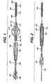
- Fig. 1 shows a lateral, cross-sectional view of a distal end of a guidewire 160 with a filter membrane 170 attached thereto.
- Fig. 1 shows guidewire 160 with a shapeable soft "floppy" tip 162 at its extreme distal end which provides flexibility and manoeuverability to guidewire 160.
- the filter membrane in Fig. 1 is illustrated in an open position.
- Guidewire 160 comprises a core wire 164, which extends into floppy tip 162, and a sheath 166.
- Filter membrane 170 is supported by a basket 169 comprising two or more filter basket wires 168, having distal ends 172 and proximal ends 174.
- the distal ends 172 of basket wires 168 are fixedly attached by distal radiopaque marker or crimp band 176 to core wire 164, and the proximal ends 174 of basket wires 168 are attached to proximal radiopaque marker or crimp band 178, which is slidable over core wire 164, optionally with a polymeric, such as polyimide, or metallic sleeve between core wire 164 and proximal ends 174.
- proximal marker 178 is fixedly attached to core wire 164, and distal marker 176, with a polymeric or metallic sleeve, is slidable over core wire 164.
- the flow of blood in Fig. 1 is toward the distal end of guidewire 160. As such, the force of the flow of blood pushes on deployed filter membrane 170 and helps to maintain filter membrane 170 in the deployed position.
- a sheath member 180 is attached to the distal end of sheath 166, sheath member 180 having a lumen 182 with a diameter and length sufficient to receive or slide over proximal marker 178.
- Sheath 166 and sheath member 180 can be either separate pieces bonded together or a continuous, integral structure.
- Sheath 166 and sheath member 180 are each made from low friction polymeric material, preferably polytetrafluoroethylene, polyethylene, nylon, or polyurethane.
- Filter membrane 170 may comprise a number of different non-metallic permeable membranes having sufficient porosity to facilitate blood flow but having sufficiently small openings to capture emboli.
- Filter membrane 170 is preferably affixed at least at its distal portion 184 to core wire 164 and/or basket wire distal ends 172 and, optionally, to basket wires 168.
- the remainder of filter membrane 170 may be unattached or, preferably, attached to basket wires 168, such as by a suitable adhesive.
- basket wires 168 are encapsulated in membrane 170.
- Basket 169 may be somewhat cylindrical in its middle with tapered, conical, proximal and distal portions. Alternately, basket 169 may be slightly spherical, optionally with a flat, cylindrical middle portion. Preferably basket 169 is from about five to about forty mm in length and from about two to about thirty mm, or from about two to about twenty mm, in diameter at its widest.
- Control handle 186 which can be used to apply torque to the guidewire.
- Control handle 186 has an opening 188 for core wire 164 so that sheath 180 can move slidably over core wire 164. For example, when sheath 180 is moved distally toward basket wires 168, filter membrane 170 collapses. Also, there may be instances where sheath 180 will be removed proximally so that other catheters or cardiovascular appliances can be introduced over core wire 164.
- Control handle 186 which functions as a torque device, also primarily functions to lock sheath 180 to core wire 164 during insertion.
- control handle 186 There are a number of known, commercially available devices for applying torque to a guidewire, which can be modified to function as control handle 186. Modification might include providing a slightly larger central lumen.
- sheath 166 and sheath member 180 are shown advanced distally so that basket wires 168 and filter member 170 are collapsed against core wire 164.
- the distal end 192 of sheath member 180 may optionally be slightly tapered to provide a better profile for insertion.
- a filter membrane 170 comprises a polymeric material such as polyurethane or silicone elastomer that has laser-drilled holes 190.
- the filter membrane may comprise fabric or non-fabric meshes, such as those used in known haemodialysis filters or heart-lung bypass machine filters. Suitable materials include polymers or physiologically acceptable metals or alloys.
- Such holes 190 are preferably only on the conical portion of filter membrane 170.
- the holes 190 could be from about 20 to about 300 ⁇ m in diameter.
- the vertical row separation of holes 190 may be from about 1.2 to 1.4 times the hole diameter and the centre-to-centre diameter of holes 190 may be from about 1.4 to 1.6 times the hole diameter; the vertical and horizontal spacing of the holes may be such that the centre-to-centre spacing of the holes is from about 1.2 to 2.0 times the hole diameter.
- the open area of the holes represents from about 10 to 50%, more preferably from up to about 40% of the filter surface.
- the hole size may be variable.
- the mesh should have pores of a size sufficient to block and capture any micro- and macro-emboli which may flow downstream from the site where the stenosis is being treated, but large enough such that blood flow is not impeded.
- the mesh used in the filter device of the invention can have a pore size of from about 20 to about 300 ⁇ m, preferably from about 50 to about 150 ⁇ m.
- the size of filter membrane 170 is such as to allow a firm fit between filter membrane 170 and an artery wall (not shown).
- the diameter of filter membrane 170 will be directly related to the artery being treated, with typical diameters ranging from about two mm to about forty mm, most preferably from about two mm to about twenty mm.
- Basket wires 168 may comprise a suitable, physiologically acceptable metal.
- Stainless steel or a nickel titanium based alloy are preferred, although titanium or other metal alloys could be used.
- Core wire 164 can be seen better in Fig. 4, where the proximal and middle portions 200 and 202 are substantially uniform in diameter, and then the distal portion 204 tapers to an end point 206. In fact, distal portion 204 could taper uniformly or, more preferably, non-uniformly, as shown in Fig. 4.
- core wire 164 is from about 250 to 300 cm in length, with an initial diameter of from about 0.2 to 1.0 mm (0.009 to 0.038 inches), preferably from about 0.35 to 0.45 mm (0.014 to 0.018 inches).
- Distal section 204 is typically from about 8 to 10 cm, with a diameter that tapers from about 0.02 to 0.13 mm (0.001 to 0.005 inches).
- Core wire 164 may optionally have a thin polymeric coating 207 for friction reduction.
- end point 206 is a solid, squat cylinder, as shown in Figs. 4 and 5.
- Floppy tip 162 preferably comprises a radiopaque helical spring 210 that is fixedly attached, e.g., by welding, brazing, or soldering, to end point 206 and, optionally, attachment point 208.
- spring coil 210 may have a polymeric or lubricious coating 212.
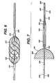
- Fig. 6 represents an alternate design where basket wires 220 are substantially helical in shape.
- Filter member 222 covers or encompasses the distal portion of basket wires 220, and the proximal and distal portions of basket wires 220 are secured by proximal radiopaque marker or crimp band 224 and distal radiopaque marker or crimp band 226, respectively.
- Markers 224 and 226 are fixed or slidable on core wire 228 as described above.
- Fig. 7 shows a filter membrane 280 supported by strut wires 282.
- the distal ends 284 of strut wires 282 are attached to the distal portion of a tubular member 286.
- a movable core wire 290 extends through a lumen 292 in tubular member 286 to a distal floppy section 294, where a helical spring coil 296 surrounds the distal portion 298 of core wire 290 and is attached to end point 300.
- the lumen 308 of sheath member 306 is large enough so that as core wire 290 is pulled proximally, or tubular member 286 is advanced distally, the distal ends 284 of strut wires 282 move into lumen 308 and collapse filter membrane 280.
- Moveable core wire 250 of the structure shown in Fig. 8 comprises a floppy tip 252 where a helical spring coil 254 encompasses the distal portion 256 of core wire 250.
- a basket wire structure component of two or more basket wires 258 supports a filter membrane 260 on the distal portion 262 of the basket structure. Distal ends 264 of the basket wires 258 are encompassed by a radiopaque marker or crimp band 266 that is attached to core wire 250 and/or spring coil 254.
- the proximal ends 268 of basket wires 258 are attached to the distal portion of a sheath 270 that surrounds core wire 250. Sheath 270 moves slidably over core wire 250 so that when sheath 270 is pulled proximally into core wire 250, filter membrane 250 collapses.
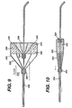
- a basket 320 comprising from four to eight strut wires 322 is secured by a distal fixed grommet 324 and a proximal slidable grommet 326.
- Grommet 326 is slidable over core wire 328.
- Filter membrane 330 is attached to or arranged upon basket 320, with the proximal section 332 of the membrane 290 being open to flow, represented by arrows 334.
- the distal portion 336 of membrane 330 forms a conical shape 340 that extends proximally.
- the filter could be deployed by, for example, a sheath or a tube fixed to the proximal slidable crimp band 336.
- This design is optimized for perfusion and emboli collection. For example, as more emboli is collected, it tends to collect in outer, non-filter areas, leaving the pores open for perfusion.
- Membrane 330 preferably has holes only in distal section 336, 340, which holes are arranged as described above. It is believed that under normal, substantially laminar flow conditions debris or emboli 342 will tend to collect in annular recesses 344.
- slidable grommet 326 is moved proximally to collapse basket 320 and membrane 336. This can be accomplished with, for example, sheath 350 or a fixed tubular member or other apparatus that is preferably slidable over the core wire.
- Fig. 11 shows a guidewire or rigid infusion tubing 360 extending over a core wire 362 that extends to a floppy tip 364, and a filter membrane 366 is supported by a filer basket 368.
- Tubing 360 extends distally to hub 372.
- Core wire 362 extends through a lumen in tubing 360 and proximal to hub 372.
- Hub 372 has a Luer fitting 374.
- Filter membrane 366 supported by filter basket 368 comprises two or more filter basket wires 376, having distal ends 378 and proximal ends 380 attached to core wire 362 and operating in a manner described above in conjunction with the description of Figs. 1 to 3.
- the infusion rigid tubing 360 may have infusion holes 370 for delivering and distributing medication through infusion holes 370 as well as through the infusion tubing end 382 to an afflicted target area of a procedure such as a peripheral thrombolysis.
- a sheath 390 is connected to the sheath member 392 at its distal end and, optionally with a distal sheath marker 394, and to a locking hub 405 of a locking mechanism 404 at its proximal end.
- the sheath locking mechanism comprises a locking hub 405 and a latch 406 which is allowed to slide independently over the infusion tubing 360.
- Sheath 390 may be moved distally and proximally along the infusion tubing 360 and locked in place to prevent any further movement along the infusion tubing 360. By sliding sheath 390 distally and proximally along the infusion tubing 390, a specific number of the infusion holes 370 may be covered or opened.
- Infusion holes 370 thereby controls the distribution and the amount of medication along the specific area of operation, i.e., the location of the exposed infusion holes 370 relative to a thrombus 396 (or atheroma, stenosis, embolism, plaque, etc.).
- Infusion holes 370 may be covered and opened alternatively by distally and proximally sliding either only the infusion tubing 360 along core wire 362, distally and proximally sliding only sheath 390 along the infusion tubing 360, or manipulating both the infusion tubing 360 along the core wire 362 and the sheath 390 along the infusion tubing 360 simultaneously.
- Sheath 390, sheath member 392 and locking hub 405 may be either separate pieces bonded together or a continuous, integral structure.
- Latch 406 is a separate piece of tubing of the same diameter as sheath 390 slidable distally and proximally along the infusion tubing 360. However, in contrast to the sheath 390, the latch 406 has a tight fit over the infusion tubing 360, enabling sheath 390 to be secured in a secured position when locking mechanism 404 is engaged or locked.
- wires, membrane, and other materials of this embodiment are consistent with those described above.
- Fig. 12 shows a dilatation balloon delivery system 360 which comprises a deployment sheath 362 and a hub 364.
- a balloon shaft 366 extends from hub 364 to the distal section 368 of deployment sheath 362, where the distal portion of balloon shaft 366 comprises an inflatable dilatation balloon 370.
- the interior 372 of balloon 370 is in fluid communication with inflation lumen 374 in balloon shaft 366 and an inflation port 376 in hub 364.
- Balloon shaft 366 also comprises a guidewire lumen 378 in fluid communication with a guidewire port 380 in hub 364 and extending through balloon 370 to a vascular filter or emboli capture device 382, as described above.
- the ends of a filter basket 384 are secured in a fixed grommet 386 and a slidable grommet 388.
- deployment sheath 362 is advanced through a patient's vascular system to a desired location.
- balloon 370 is collapsed, and vascular filter 382 is somewhat compressed.
- deployment sheath 362 is pulled in the proximal direction, and then balloon 370 is expanded to dilate a vessel.
- Vascular filter 382 expands as grommet 388 slides in the proximal direction.
- sheath 362 may be advanced distally to collapse vascular filter 382.
- vascular filter 382 is collapsed, sheath 362, collapsed balloon 370, and collapsed vascular filter 382 may be withdrawn together in the proximal direction.
- Fig. 13 shows a stent delivery system 360 which comprises a deployment sheath 362 and a hub 364.
- a balloon shaft 366 extends from hub 364 to the distal section 368 of deployment sheath 362, where the distal portion of inflatable balloon catheter shaft 366 comprises an expandable balloon 370.
- the interior 372 of balloon 370 is in fluid communication with an inflation lumen 374 in balloon catheter shaft 366 and an inflation port 376 in hub 364.
- Balloon shaft 366 also comprises a guidewire lumen 378 in fluid communication with a guidewire port 380 in hub 364 and extending through balloon 370 to a vascular filter or emboli capture device 382, as described above.
- the ends of a filter basket 384 are secured in a fixed grommet 386 and a slidable grommet 388.
- An expandable stent 390 is positioned annularly adjacent to balloon 370.
- deployment sheath 362 is advanced through a patient's vascular system to a desired location.
- balloon 370 is either collapsed or expanded only so far as to hold stent 386 in position, and vascular filter 382 is somewhat compressed.
- deployment sheath 362 is pulled in the proximal direction, and then balloon 370 is expanded to secure stent 390 in position.
- Vascular filter 382 expands as grommet 388 slides in the proximal direction.
- sheath 362 may be advanced distally to collapse vascular filter 382. After vascular filter 382 is collapsed, sheath 362 and vascular filter 382 can be withdrawn together in the proximal direction.
- stent 390 could be a self-expanding stent that is releasably positioned on a delivery catheter, for example as disclosed in US-5246445 and US-5372600.
- the stent delivery catheter would comprise a lumen for release wires, etc., as well as a lumen for a guidewire lumen in connection with a vascular filter system.
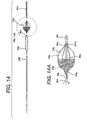
- Fig. 14 shows vascular filter system which comprises a guidewire 360 with a core wire 362 extending distally into floppy tip 364.
- Vascular filter 366 comprises a filter membrane 368 positioned in a distally facing manner on filter basket 370 comprised of 6 to 8 struts or wires 372.
- the distal 374 and proximal 376 ends of basket wires 372 are held by proximal grommet 378 and distal sliding grommet 380.
- filter basket 370 has radiopaque markers 382.
- a sheath 388 with expanded distal sheath section 390 is arranged concentrically around guidewire 360.
- the vascular filter system will be inserted through a guide catheter in a patient's femoral artery and then advanced through the aorta to a position adjacent the patient's left ventricle.
- any emboli or thrombus produced will be captured in filter membrane 368.
- sheath 388 and filter basket 370 are moved relative to one another so that the distal section 390 of sheath 388 causes filter basket 370 to collapse, whereupon filter basket 370 and captured material are withdrawn with the sheath.
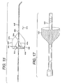
- FIG. 9 The apparatus shown in Fig. 9 can be modified as shown in Fig. 15.
- a basket 400 comprised of from four to eight strut wires 402 is secured by a proximal fixed grommet 404 and a distal slidable grommet 406.
- Grommet 406 is slidable over core wire 408.
- Filter membrane 410 is attached to or arranged upon basket 412, with the proximal section 414 of the membrane 410 being open to flow, represented by arrow 416.
- the proximal portion 414 of membrane 410 forms a conical shape that extends distally.
- the filter may be deployed by, for example, a sheath, a tube, or a wire fixed to the distal slidable crimp band 406.
- Membrane 410 preferably has holes only in proximal section 414, which holes are arranged as described above. It is believed that under normal, substantially laminar flow conditions debris or emboli 418 will tend to collect in annular recesses 420.
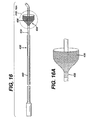
- Fig. 16 depicts a guide catheter 430 comprising a catheter shaft 432 having a distal end 434.
- a filter membrane 436 having a flexible support or structure is arranged, distally facing, on said distal end 434. The proximal portion of filter membrane 436 is secured at band 438.
- a sheath 440 is arranged concentrically around guide catheter shaft 432 so that when sheath 440 is advanced distally, filter membrane 436 collapses. It is contemplated that other means may be devised for collapsing filter membrane 436, such as a wire.
- Guide catheter 430 will preferably have a lumen 442 capable of receiving another device, such as an ablation catheter (not shown).
- the distal portion of the guide catheter will be advanced through the femoral artery into the left ventricle.
- Fig. 17 shows an ablation catheter 450 which includes a filter membrane 452 arranged proximal to the distal end of catheter 450 by means discussed above, such as a sheath concentric to the catheter or a wire, or other means.
Landscapes
- Health & Medical Sciences (AREA)
- Cardiology (AREA)
- Oral & Maxillofacial Surgery (AREA)
- Transplantation (AREA)
- Engineering & Computer Science (AREA)
- Biomedical Technology (AREA)
- Heart & Thoracic Surgery (AREA)
- Vascular Medicine (AREA)
- Life Sciences & Earth Sciences (AREA)
- Animal Behavior & Ethology (AREA)
- General Health & Medical Sciences (AREA)
- Public Health (AREA)
- Veterinary Medicine (AREA)
- Surgical Instruments (AREA)
- Media Introduction/Drainage Providing Device (AREA)
- Filtering Materials (AREA)
- Materials For Medical Uses (AREA)
Abstract
Description
Also, there may be instances where
Claims (21)
- A removable percutaneous vascular filter system for blocking emboli in a vessel while allowing continued perfusion of blood comprising:a guidewire having distal and proximal ends,a filter comprising (a) a non-metallic, porous, filter membrane having a distal portion and a proximal free end portion, wherein the pore size of the porous filter membrane is in the range of from about 20 to about 300 µm, and (b) a filter membrane support structure extending from the flexible filter membrane distal portion to the flexible filter membrane proximal portion, wherein said filter membrane distal portion is pivotally attached to the guidewire near said distal end of the guidewire and wherein the filter membrane proximal free end portion is substantially parallel to the guidewire in its collapsed state; anddeploying means operatively connected to the filter to cause the filter membrane proximal free end portion to move from a position substantially parallel to the guidewire to a position removed from the longitudinal axis of the guidewire to cause the flexible filter member to form a substantially conical shape, and to form a generally sealing relationship with the wall of said vessel.
- A system as claimed in claim 1, further comprising an infusion catheter having a proximal end and a distal end, and at least one infusion hole for causing medication to be delivered to a site, with said infusion catheter coaxially disposed around said guidewire, and said at least one infusion hole positioned proximal to said filter.
- A system as claimed in claim 1, further comprising a balloon catheter shaft having a proximal end and a distal end, and at least one lumen, the proximal end having a hub comprising first and second ports, and the distal end comprising an inflatable balloon, with said balloon catheter coaxially disposed around said guidewire, and said inflatable balloon positioned proximal to said filter.
- A system as claimed in claim 1, further comprising a stent coaxially disposed around said inflatable balloon.
- A system as claimed in any one of claims 1 to 4, wherein the pore size of the porous filter membrane is variable.
- A percutaneous vascular filter system comprising:a guidewire having proximal and distal ends;a filter arranged around said guidewire, said filter (a) a non-metallic, porous, filter membrane having a distal portion and a proximal free end portion, wherein the pore size of the porous filter membrane is in the range of from about 20 to about 300 µm, and (b) a filter membrane support structure extending from the flexible filter membrane distal portion to the flexible filter membrane proximal portion, wherein the flexible membrane distal portion is pivotally attached to the guidewire adjacent its distal end and the proximal end of the filter is attached to the guidewire; anda sheath arranged around said guidewire and having proximal and distal ends, the distal end of the sheath having a lumen of sufficient diameter to slide over the proximal portion of the filter.
- A system as claimed in claim 6, further comprising an infusion catheter having a proximal end and a distal end, and at least one infusion hole for causing medication to be delivered to a site, with said infusion catheter coaxially disposed around said guidewire, and said at least one infusion hole positioned proximal to said filter.
- A system as claimed in claim 6, further comprising a balloon catheter shaft having a proximal end and a distal end, and at least one lumen, the proximal end having a hub comprising first and second ports, and the distal end comprising an inflatable balloon, with said balloon catheter coaxially disposed around said guidewire, and said inflatable balloon positioned proximal to said filter.
- A system as claimed in claim 8, further comprising a stent coaxially disposed around said inflatable balloon.
- A system as claimed in any one of claims 6 to 9, wherein the pore size of the porous filter membrane is variable.
- A removable percutaneous vascular filter system for blocking emboli in a vessel while allowing continued perfusion of blood, comprising:a guidewire having distal and proximal ends;a filter comprising (a) a non-metallic, porous, filter membrane having a proximal portion and a distal free end portion, wherein the pore size of the porous filter membrane is in the range of from about 20 to about 300 microns, and (b) a filter membrane support structure extending from the flexible filter membrane distal portion to the flexible filter membrane proximal portion, wherein said filter membrane support structure is pivotally attached to the guidewire near said distal end of the guidewire and wherein the filter membrane distal free end portion is substantially parallel to the guidewire in its collapsed state; anddeploying means operatively connected to the filter to cause the filter membrane proximal free end portion to move from a position substantially parallel to the guidewire to a position removed from the longitudinal axis of the guidewire to cause the flexible filter member to form a substantially conical shape, and to form a generally sealing relationship with the wall of said vessel.
- A removable percutaneous vascular filter system for blocking emboli in a vessel while allowing continued perfusion of blood, comprising:a guidewire having distal and proximal ends;a filter comprising (a) a non-metallic, porous, filter membrane having a proximal portion and a distal free end portion, wherein the pore size of the porous filter membrane is in the range of from about 20 to about 300 µm, and (b) a filter membrane support structure extending from the flexible filter membrane distal portion to the flexible filter membrane proximal portion, wherein said filter membrane support structure is pivotally attached to the guidewire near said distal end of the guidewire and wherein the filter membrane distal free end portion is substantially parallel to the guidewire in its collapsed state; anda sheath concentrically arranged around said guidewire and having proximal and distal ends, the distal end of the sheath having a lumen of sufficient diameter to slide over the proximal portion of the filter.
- A system as claimed in claim 11 or claim 12, wherein the pore size of the porous filter membrane is variable.
- A device for use with a catheter for ablation within the body, wherein the catheter has a proximal end and distal end, and an outer surface, said distal end having ablative capability, the device comprising a distally facing, porous, filter membrane and filter membrane support structure arranged on the outer surface of the catheter proximal to its distal end.
- A device as claimed in claim 14, wherein the catheter has an outer sheath arranged thereon, which outer sheath can be advanced distally to collapse the filter.
- A device as claimed in claim 14, wherein the distally facing, porous filter membrane comprises pores with diameters in the range of from about 20 to about 300 µm.
- A device as claimed in any one of claims 14 to 16, in combination with a catheter.
- An improved device for use with a infusion catheter for causing medication to be delivered to a thrombus, the improvement comprising:a vascular filter positioned distal to said infusion catheter;said vascular filter comprising a guidewire having distal and proximal ends, with said infusion catheter coaxially disposed around said guidewire;said vascular filter further comprising (a) a non-metallic, porous filter membrane having a distal portion and a proximal free end portion, wherein the pore size of the porous filter membrane is in the range of from about 20 to about 300 µm, and (b) a filter membrane support structure extending from the flexible filter membrane distal portion to the flexible filter membrane proximal portion, and deploying means operatively connected to the filter to cause the filter membrane support structure to form a substantially conical shape, and to form a generally sealing relationship with the wall of said vessel.
- An improved device for use with a balloon catheter, the improvement comprising:a vascular filter positioned distal to said balloon catheter;said vascular filter comprising a guidewire having distal and proximal ends, with said balloon catheter coaxially disposed around said guidewire;said vascular filter further comprising (a) a non-metallic, porous filter membrane having a distal portion and a proximal free end portion, wherein the pore size of the porous filter membrane is in the range of from about 20 to about 300 µm, and (b) a filter membrane support structure extending from the flexible filter membrane distal portion to the flexible membrane proximal portion, and deploying means operatively connected to the filter to cause the filter membrane support structure to form a substantially conical shape, and to form a generally sealing relationship with the wall of said vessel.
- An improved device for use with a stent delivery system, the improvement comprising:a vascular filter positioned distal to said stent delivery system;said vascular filter comprising a guidewire having distal and proximal ends, with said stent delivery system coaxially disposed around said guidewire;said vascular filter further comprising (a) a non-metallic, porous filter membrane having a distal portion and a proximal free end portion, wherein the pore size of the porous filter membrane is in the range of from about 20 to about 300 µm, and (b) a filter membrane support structure extending from the flexible filter membrane distal portion to the flexible filter membrane proximal portion, and deploying means operatively connected to the filter to cause the filter membrane support structure to form a substantially conical shape, and to form a generally sealing relationship with the wall of said vessel.
- A device as claimed in any one of claims 14 to 20, wherein the pore size of the porous filter membrane is variable.
Applications Claiming Priority (2)
| Application Number | Priority Date | Filing Date | Title |
|---|---|---|---|
| US10/045,296 US20020138094A1 (en) | 1999-02-12 | 2001-11-07 | Vascular filter system |
| US45296 | 2001-11-07 |
Publications (3)
| Publication Number | Publication Date |
|---|---|
| EP1310219A2 true EP1310219A2 (en) | 2003-05-14 |
| EP1310219A3 EP1310219A3 (en) | 2003-06-04 |
| EP1310219B1 EP1310219B1 (en) | 2007-01-03 |
Family
ID=21937082
Family Applications (1)
| Application Number | Title | Priority Date | Filing Date |
|---|---|---|---|
| EP02257674A Expired - Lifetime EP1310219B1 (en) | 2001-11-07 | 2002-11-06 | Vascular filter system |
Country Status (11)
| Country | Link |
|---|---|
| US (2) | US20020138094A1 (en) |
| EP (1) | EP1310219B1 (en) |
| JP (1) | JP4387092B2 (en) |
| AR (1) | AR037262A1 (en) |
| AT (1) | ATE349971T1 (en) |
| AU (1) | AU2002301808B2 (en) |
| BR (1) | BR0206890B1 (en) |
| CA (1) | CA2411229C (en) |
| DE (1) | DE60217264T2 (en) |
| ES (1) | ES2278880T3 (en) |
| MX (1) | MXPA02010930A (en) |
Cited By (19)
| Publication number | Priority date | Publication date | Assignee | Title |
|---|---|---|---|---|
| WO2007047818A1 (en) * | 2005-10-18 | 2007-04-26 | Cook Incorporated | Invertible filter for embolic protection |
| WO2007127535A1 (en) * | 2006-04-24 | 2007-11-08 | Boston Scientific Limited | Self-flushing catheter |
| US8152831B2 (en) | 2005-11-17 | 2012-04-10 | Cook Medical Technologies Llc | Foam embolic protection device |
| US8182508B2 (en) | 2005-10-04 | 2012-05-22 | Cook Medical Technologies Llc | Embolic protection device |
| US8187298B2 (en) | 2005-08-04 | 2012-05-29 | Cook Medical Technologies Llc | Embolic protection device having inflatable frame |
| US8216269B2 (en) | 2005-11-02 | 2012-07-10 | Cook Medical Technologies Llc | Embolic protection device having reduced profile |
| US8221446B2 (en) | 2005-03-15 | 2012-07-17 | Cook Medical Technologies | Embolic protection device |
| US8252018B2 (en) | 2007-09-14 | 2012-08-28 | Cook Medical Technologies Llc | Helical embolic protection device |
| US8377092B2 (en) | 2005-09-16 | 2013-02-19 | Cook Medical Technologies Llc | Embolic protection device |
| US8388644B2 (en) | 2008-12-29 | 2013-03-05 | Cook Medical Technologies Llc | Embolic protection device and method of use |
| US8419748B2 (en) | 2007-09-14 | 2013-04-16 | Cook Medical Technologies Llc | Helical thrombus removal device |
| US8632562B2 (en) | 2005-10-03 | 2014-01-21 | Cook Medical Technologies Llc | Embolic protection device |
| US8795315B2 (en) | 2004-10-06 | 2014-08-05 | Cook Medical Technologies Llc | Emboli capturing device having a coil and method for capturing emboli |
| WO2014141226A1 (en) | 2013-03-15 | 2014-09-18 | National University Of Ireland | A device suitable for removing matter from inside the lumen and the wall of a body lumen |
| US8945169B2 (en) | 2005-03-15 | 2015-02-03 | Cook Medical Technologies Llc | Embolic protection device |
| US9138307B2 (en) | 2007-09-14 | 2015-09-22 | Cook Medical Technologies Llc | Expandable device for treatment of a stricture in a body vessel |
| US9901434B2 (en) | 2007-02-27 | 2018-02-27 | Cook Medical Technologies Llc | Embolic protection device including a Z-stent waist band |
| US9907639B2 (en) | 2006-09-19 | 2018-03-06 | Cook Medical Technologies Llc | Apparatus and methods for in situ embolic protection |
| US12465478B2 (en) | 2017-01-20 | 2025-11-11 | W. L. Gore & Associates, Inc. | Embolic filter system |
Families Citing this family (339)
| Publication number | Priority date | Publication date | Assignee | Title |
|---|---|---|---|---|
| IE980920A1 (en) * | 1997-11-07 | 1999-05-19 | Salviac Ltd | An embolic protection device |
| US7491216B2 (en) | 1997-11-07 | 2009-02-17 | Salviac Limited | Filter element with retractable guidewire tip |
| JP4187411B2 (en) | 1998-01-30 | 2008-11-26 | セント ジュード メディカル エーティージー, インコーポレイテッド | Device for use in closing a septal defect |
| US7044134B2 (en) | 1999-11-08 | 2006-05-16 | Ev3 Sunnyvale, Inc | Method of implanting a device in the left atrial appendage |
| US7713282B2 (en) | 1998-11-06 | 2010-05-11 | Atritech, Inc. | Detachable atrial appendage occlusion balloon |
| US7128073B1 (en) | 1998-11-06 | 2006-10-31 | Ev3 Endovascular, Inc. | Method and device for left atrial appendage occlusion |
| US7799051B2 (en) | 1999-05-07 | 2010-09-21 | Salviac Limited | Support frame for an embolic protection device |
| US6918921B2 (en) | 1999-05-07 | 2005-07-19 | Salviac Limited | Support frame for an embolic protection device |
| AU3844499A (en) | 1999-05-07 | 2000-11-21 | Salviac Limited | Improved filter element for embolic protection device |
| EP1176924B1 (en) * | 1999-05-07 | 2005-01-12 | Salviac Limited | Improved filter element for embolic protection device |
| US8002790B2 (en) | 1999-05-07 | 2011-08-23 | Salviac Limited | Support frame for an embolic protection device |
| US7014647B2 (en) | 1999-05-07 | 2006-03-21 | Salviac Limited | Support frame for an embolic protection device |
| US6964672B2 (en) | 1999-05-07 | 2005-11-15 | Salviac Limited | Support frame for an embolic protection device |
| US8414543B2 (en) | 1999-10-22 | 2013-04-09 | Rex Medical, L.P. | Rotational thrombectomy wire with blocking device |
| US6994092B2 (en) | 1999-11-08 | 2006-02-07 | Ev3 Sunnyvale, Inc. | Device for containing embolic material in the LAA having a plurality of tissue retention structures |
| US6575997B1 (en) | 1999-12-23 | 2003-06-10 | Endovascular Technologies, Inc. | Embolic basket |
| US6402771B1 (en) | 1999-12-23 | 2002-06-11 | Guidant Endovascular Solutions | Snare |
| US6660021B1 (en) | 1999-12-23 | 2003-12-09 | Advanced Cardiovascular Systems, Inc. | Intravascular device and system |
| US6695813B1 (en) | 1999-12-30 | 2004-02-24 | Advanced Cardiovascular Systems, Inc. | Embolic protection devices |
| US6540722B1 (en) | 1999-12-30 | 2003-04-01 | Advanced Cardiovascular Systems, Inc. | Embolic protection devices |
| US7918820B2 (en) | 1999-12-30 | 2011-04-05 | Advanced Cardiovascular Systems, Inc. | Device for, and method of, blocking emboli in vessels such as blood arteries |
| GB2369575A (en) | 2000-04-20 | 2002-06-05 | Salviac Ltd | An embolic protection system |
| JP2004513673A (en) * | 2000-05-09 | 2004-05-13 | ペイエオン・インコーポレーテツド | System and method for three-dimensional reconstruction of arteries |
| US6964670B1 (en) | 2000-07-13 | 2005-11-15 | Advanced Cardiovascular Systems, Inc. | Embolic protection guide wire |
| CA2419811A1 (en) | 2000-08-18 | 2002-02-28 | Atritech, Inc. | Expandable implant devices for filtering blood flow from atrial appendages |
| US6537294B1 (en) | 2000-10-17 | 2003-03-25 | Advanced Cardiovascular Systems, Inc. | Delivery systems for embolic filter devices |
| US6893451B2 (en) | 2000-11-09 | 2005-05-17 | Advanced Cardiovascular Systems, Inc. | Apparatus for capturing objects beyond an operative site utilizing a capture device delivered on a medical guide wire |
| US6506203B1 (en) | 2000-12-19 | 2003-01-14 | Advanced Cardiovascular Systems, Inc. | Low profile sheathless embolic protection system |
| US6974468B2 (en) * | 2001-02-28 | 2005-12-13 | Scimed Life Systems, Inc. | Filter retrieval catheter |
| US7338514B2 (en) | 2001-06-01 | 2008-03-04 | St. Jude Medical, Cardiology Division, Inc. | Closure devices, related delivery methods and tools, and related methods of use |
| US7044952B2 (en) | 2001-06-06 | 2006-05-16 | Sdgi Holdings, Inc. | Dynamic multilock anterior cervical plate system having non-detachably fastened and moveable segments |
| US6599307B1 (en) | 2001-06-29 | 2003-07-29 | Advanced Cardiovascular Systems, Inc. | Filter device for embolic protection systems |
| US7338510B2 (en) | 2001-06-29 | 2008-03-04 | Advanced Cardiovascular Systems, Inc. | Variable thickness embolic filtering devices and method of manufacturing the same |
| US6638294B1 (en) | 2001-08-30 | 2003-10-28 | Advanced Cardiovascular Systems, Inc. | Self furling umbrella frame for carotid filter |
| US6592606B2 (en) | 2001-08-31 | 2003-07-15 | Advanced Cardiovascular Systems, Inc. | Hinged short cage for an embolic protection device |
| US8262689B2 (en) | 2001-09-28 | 2012-09-11 | Advanced Cardiovascular Systems, Inc. | Embolic filtering devices |
| US6890340B2 (en) * | 2001-11-29 | 2005-05-10 | Medtronic Vascular, Inc. | Apparatus for temporary intraluminal protection |
| WO2003055413A2 (en) | 2001-12-21 | 2003-07-10 | Salviac Limited | A support frame for an embolic protection device |
| US7241304B2 (en) | 2001-12-21 | 2007-07-10 | Advanced Cardiovascular Systems, Inc. | Flexible and conformable embolic filtering devices |
| DE60315425T2 (en) * | 2002-03-05 | 2008-06-26 | Salviac Ltd. | SYSTEM FOR PROTECTION FROM EMBOLICS |
| US20030187495A1 (en) * | 2002-04-01 | 2003-10-02 | Cully Edward H. | Endoluminal devices, embolic filters, methods of manufacture and use |
| US7976564B2 (en) | 2002-05-06 | 2011-07-12 | St. Jude Medical, Cardiology Division, Inc. | PFO closure devices and related methods of use |
| US8070769B2 (en) * | 2002-05-06 | 2011-12-06 | Boston Scientific Scimed, Inc. | Inverted embolic protection filter |
| US6887258B2 (en) | 2002-06-26 | 2005-05-03 | Advanced Cardiovascular Systems, Inc. | Embolic filtering devices for bifurcated vessels |
| US7172614B2 (en) | 2002-06-27 | 2007-02-06 | Advanced Cardiovascular Systems, Inc. | Support structures for embolic filtering devices |
| US7479151B2 (en) | 2002-08-05 | 2009-01-20 | Gardia Medical Ltd. | Embolism filter with self-deployable guidewire stop |
| EP1402826B1 (en) * | 2002-08-20 | 2013-06-12 | Nipro Corporation | Thrombus capture catheter |
| DE10242444A1 (en) * | 2002-09-11 | 2004-04-01 | pfm Produkte für die Medizin AG | extractor |
| US7252675B2 (en) | 2002-09-30 | 2007-08-07 | Advanced Cardiovascular, Inc. | Embolic filtering devices |
| US7331973B2 (en) | 2002-09-30 | 2008-02-19 | Avdanced Cardiovascular Systems, Inc. | Guide wire with embolic filtering attachment |
| US20040093012A1 (en) | 2002-10-17 | 2004-05-13 | Cully Edward H. | Embolic filter frame having looped support strut elements |
| US20040088000A1 (en) | 2002-10-31 | 2004-05-06 | Muller Paul F. | Single-wire expandable cages for embolic filtering devices |
| US20040153056A1 (en) * | 2002-11-11 | 2004-08-05 | Berchtold Holding Gmbh, A German Corporation | Probe |
| US8591540B2 (en) | 2003-02-27 | 2013-11-26 | Abbott Cardiovascular Systems Inc. | Embolic filtering devices |
| US8372112B2 (en) | 2003-04-11 | 2013-02-12 | St. Jude Medical, Cardiology Division, Inc. | Closure devices, related delivery methods, and related methods of use |
| US20040267306A1 (en) | 2003-04-11 | 2004-12-30 | Velocimed, L.L.C. | Closure devices, related delivery methods, and related methods of use |
| US7597704B2 (en) * | 2003-04-28 | 2009-10-06 | Atritech, Inc. | Left atrial appendage occlusion device with active expansion |
| US7604649B2 (en) * | 2003-04-29 | 2009-10-20 | Rex Medical, L.P. | Distal protection device |
| US7331976B2 (en) | 2003-04-29 | 2008-02-19 | Rex Medical, L.P. | Distal protection device |
| US7735493B2 (en) | 2003-08-15 | 2010-06-15 | Atritech, Inc. | System and method for delivering a left atrial appendage containment device |
| US7892251B1 (en) | 2003-11-12 | 2011-02-22 | Advanced Cardiovascular Systems, Inc. | Component for delivering and locking a medical device to a guide wire |
| US7056286B2 (en) | 2003-11-12 | 2006-06-06 | Adrian Ravenscroft | Medical device anchor and delivery system |
| US7780725B2 (en) | 2004-06-16 | 2010-08-24 | Sadra Medical, Inc. | Everting heart valve |
| US9526609B2 (en) | 2003-12-23 | 2016-12-27 | Boston Scientific Scimed, Inc. | Methods and apparatus for endovascularly replacing a patient's heart valve |
| US7748389B2 (en) * | 2003-12-23 | 2010-07-06 | Sadra Medical, Inc. | Leaflet engagement elements and methods for use thereof |
| US9005273B2 (en) | 2003-12-23 | 2015-04-14 | Sadra Medical, Inc. | Assessing the location and performance of replacement heart valves |
| EP2526899B1 (en) | 2003-12-23 | 2014-01-29 | Sadra Medical, Inc. | Repositionable heart valve |
| US8828078B2 (en) | 2003-12-23 | 2014-09-09 | Sadra Medical, Inc. | Methods and apparatus for endovascular heart valve replacement comprising tissue grasping elements |
| US7381219B2 (en) | 2003-12-23 | 2008-06-03 | Sadra Medical, Inc. | Low profile heart valve and delivery system |
| US8579962B2 (en) | 2003-12-23 | 2013-11-12 | Sadra Medical, Inc. | Methods and apparatus for performing valvuloplasty |
| US20050137694A1 (en) | 2003-12-23 | 2005-06-23 | Haug Ulrich R. | Methods and apparatus for endovascularly replacing a patient's heart valve |
| US8840663B2 (en) | 2003-12-23 | 2014-09-23 | Sadra Medical, Inc. | Repositionable heart valve method |
| US20120041550A1 (en) | 2003-12-23 | 2012-02-16 | Sadra Medical, Inc. | Methods and Apparatus for Endovascular Heart Valve Replacement Comprising Tissue Grasping Elements |
| US7959666B2 (en) | 2003-12-23 | 2011-06-14 | Sadra Medical, Inc. | Methods and apparatus for endovascularly replacing a heart valve |
| US7824442B2 (en) * | 2003-12-23 | 2010-11-02 | Sadra Medical, Inc. | Methods and apparatus for endovascularly replacing a heart valve |
| US20050137687A1 (en) | 2003-12-23 | 2005-06-23 | Sadra Medical | Heart valve anchor and method |
| US20050137691A1 (en) * | 2003-12-23 | 2005-06-23 | Sadra Medical | Two piece heart valve and anchor |
| US7445631B2 (en) | 2003-12-23 | 2008-11-04 | Sadra Medical, Inc. | Methods and apparatus for endovascularly replacing a patient's heart valve |
| US8343213B2 (en) | 2003-12-23 | 2013-01-01 | Sadra Medical, Inc. | Leaflet engagement elements and methods for use thereof |
| US8287584B2 (en) * | 2005-11-14 | 2012-10-16 | Sadra Medical, Inc. | Medical implant deployment tool |
| US11278398B2 (en) | 2003-12-23 | 2022-03-22 | Boston Scientific Scimed, Inc. | Methods and apparatus for endovascular heart valve replacement comprising tissue grasping elements |
| US7329279B2 (en) * | 2003-12-23 | 2008-02-12 | Sadra Medical, Inc. | Methods and apparatus for endovascularly replacing a patient's heart valve |
| US20050137686A1 (en) * | 2003-12-23 | 2005-06-23 | Sadra Medical, A Delaware Corporation | Externally expandable heart valve anchor and method |
| US8603160B2 (en) * | 2003-12-23 | 2013-12-10 | Sadra Medical, Inc. | Method of using a retrievable heart valve anchor with a sheath |
| US7824443B2 (en) | 2003-12-23 | 2010-11-02 | Sadra Medical, Inc. | Medical implant delivery and deployment tool |
| US8182528B2 (en) | 2003-12-23 | 2012-05-22 | Sadra Medical, Inc. | Locking heart valve anchor |
| US7678129B1 (en) | 2004-03-19 | 2010-03-16 | Advanced Cardiovascular Systems, Inc. | Locking component for an embolic filter assembly |
| US8801746B1 (en) | 2004-05-04 | 2014-08-12 | Covidien Lp | System and method for delivering a left atrial appendage containment device |
| IL169696A (en) * | 2004-07-22 | 2014-12-31 | Cordis Corp | A device for filtering blood in a vessel with helical elements |
| EP1853197B1 (en) * | 2004-09-17 | 2011-08-17 | Nitinol Development Corporation | Shape memory thin film embolic protection device |
| US20060149312A1 (en) * | 2004-12-30 | 2006-07-06 | Edward Arguello | Distal protection device with improved wall apposition |
| US20080021497A1 (en) * | 2005-01-03 | 2008-01-24 | Eric Johnson | Endoluminal filter |
| DE102005003632A1 (en) | 2005-01-20 | 2006-08-17 | Fraunhofer-Gesellschaft zur Förderung der angewandten Forschung e.V. | Catheter for the transvascular implantation of heart valve prostheses |
| US8109941B2 (en) * | 2005-02-28 | 2012-02-07 | Boston Scientific Scimed, Inc. | Distal release retrieval assembly and related methods of use |
| US9259305B2 (en) | 2005-03-31 | 2016-02-16 | Abbott Cardiovascular Systems Inc. | Guide wire locking mechanism for rapid exchange and other catheter systems |
| US7962208B2 (en) | 2005-04-25 | 2011-06-14 | Cardiac Pacemakers, Inc. | Method and apparatus for pacing during revascularization |
| US8109962B2 (en) | 2005-06-20 | 2012-02-07 | Cook Medical Technologies Llc | Retrievable device having a reticulation portion with staggered struts |
| US7850708B2 (en) | 2005-06-20 | 2010-12-14 | Cook Incorporated | Embolic protection device having a reticulated body with staggered struts |
| US7771452B2 (en) | 2005-07-12 | 2010-08-10 | Cook Incorporated | Embolic protection device with a filter bag that disengages from a basket |
| US7766934B2 (en) | 2005-07-12 | 2010-08-03 | Cook Incorporated | Embolic protection device with an integral basket and bag |
| US7712606B2 (en) | 2005-09-13 | 2010-05-11 | Sadra Medical, Inc. | Two-part package for medical implant |
| US7972359B2 (en) | 2005-09-16 | 2011-07-05 | Atritech, Inc. | Intracardiac cage and method of delivering same |
| US20070135826A1 (en) | 2005-12-01 | 2007-06-14 | Steve Zaver | Method and apparatus for delivering an implant without bias to a left atrial appendage |
| US20070213813A1 (en) | 2005-12-22 | 2007-09-13 | Symetis Sa | Stent-valves for valve replacement and associated methods and systems for surgery |
| EP1986568B1 (en) | 2006-02-03 | 2017-04-05 | Covidien LP | Methods and devices for restoring blood flow within blocked vasculature |
| CN101415379B (en) | 2006-02-14 | 2012-06-20 | 萨德拉医学公司 | Systems for delivering medical implants |
| US7846175B2 (en) | 2006-04-03 | 2010-12-07 | Medrad, Inc. | Guidewire and collapsable filter system |
| US9480548B2 (en) * | 2006-09-11 | 2016-11-01 | Edwards Lifesciences Ag | Embolic protection device and method of use |
| US20100179647A1 (en) * | 2006-09-11 | 2010-07-15 | Carpenter Judith T | Methods of reducing embolism to cerebral circulation as a consequence of an index cardiac procedure |
| US9339367B2 (en) | 2006-09-11 | 2016-05-17 | Edwards Lifesciences Ag | Embolic deflection device |
| US8460335B2 (en) * | 2006-09-11 | 2013-06-11 | Embrella Cardiovascular, Inc. | Method of deflecting emboli from the cerebral circulation |
| US20100179583A1 (en) * | 2006-09-11 | 2010-07-15 | Carpenter Judith T | Methods of deploying and retrieving an embolic diversion device |
| US20150335415A1 (en) * | 2007-01-31 | 2015-11-26 | Stanley Batiste | Intravenous filter with guidewire and catheter access guide |
| US7896915B2 (en) | 2007-04-13 | 2011-03-01 | Jenavalve Technology, Inc. | Medical device for treating a heart valve insufficiency |
| US8216209B2 (en) | 2007-05-31 | 2012-07-10 | Abbott Cardiovascular Systems Inc. | Method and apparatus for delivering an agent to a kidney |
| US9144509B2 (en) | 2007-05-31 | 2015-09-29 | Abbott Cardiovascular Systems Inc. | Method and apparatus for delivering an agent to a kidney |
| US9149610B2 (en) | 2007-05-31 | 2015-10-06 | Abbott Cardiovascular Systems Inc. | Method and apparatus for improving delivery of an agent to a kidney |
| US9364586B2 (en) | 2007-05-31 | 2016-06-14 | Abbott Cardiovascular Systems Inc. | Method and apparatus for improving delivery of an agent to a kidney |
| US7867273B2 (en) | 2007-06-27 | 2011-01-11 | Abbott Laboratories | Endoprostheses for peripheral arteries and other body vessels |
| EP2022397A1 (en) * | 2007-08-08 | 2009-02-11 | ProRhythm, Inc. | Miniature circular mapping catheter |
| US8613753B2 (en) | 2007-08-31 | 2013-12-24 | BiO2 Medical, Inc. | Multi-lumen central access vena cava filter apparatus and method of using same |
| US8668712B2 (en) | 2007-08-31 | 2014-03-11 | BiO2 Medical, Inc. | Multi-lumen central access vena cava filter apparatus and method of using same |
| WO2009032834A1 (en) | 2007-09-07 | 2009-03-12 | Crusader Medical Llc | Percutaneous permanent retrievable vascular filter |
| US8795318B2 (en) * | 2007-09-07 | 2014-08-05 | Merit Medical Systems, Inc. | Percutaneous retrievable vascular filter |
| US20090105746A1 (en) * | 2007-10-17 | 2009-04-23 | Gardia Medical Ltd | Guidewire stop |
| US7819844B2 (en) | 2007-10-17 | 2010-10-26 | Gardia Medical Ltd. | Guidewire stop |
| US11589880B2 (en) | 2007-12-20 | 2023-02-28 | Angiodynamics, Inc. | System and methods for removing undesirable material within a circulatory system utilizing during a surgical procedure |
| WO2011104269A1 (en) | 2008-02-26 | 2011-09-01 | Jenavalve Technology Inc. | Stent for the positioning and anchoring of a valvular prosthesis in an implantation site in the heart of a patient |
| US9044318B2 (en) | 2008-02-26 | 2015-06-02 | Jenavalve Technology Gmbh | Stent for the positioning and anchoring of a valvular prosthesis |
| US9402707B2 (en) | 2008-07-22 | 2016-08-02 | Neuravi Limited | Clot capture systems and associated methods |
| JP5607639B2 (en) | 2008-10-10 | 2014-10-15 | サドラ メディカル インコーポレイテッド | Medical devices and systems |
| US20100125265A1 (en) * | 2008-11-20 | 2010-05-20 | Medtronic Vascular, Inc. | Cell Delivery System to Induce Cell Growth and Angiogenesis |
| US8444577B2 (en) * | 2009-01-05 | 2013-05-21 | Cook Medical Technologies Llc | Medical guide wire |
| US9326843B2 (en) * | 2009-01-16 | 2016-05-03 | Claret Medical, Inc. | Intravascular blood filters and methods of use |
| US20170202657A1 (en) | 2009-01-16 | 2017-07-20 | Claret Medical, Inc. | Intravascular blood filters and methods of use |
| EP2387427B1 (en) | 2009-01-16 | 2014-08-27 | Claret Medical, Inc. | Intravascular blood filter |
| WO2010102307A1 (en) | 2009-03-06 | 2010-09-10 | Lazarus Effect, Inc. | Retrieval systems and methods for use thereof |
| WO2010141417A2 (en) * | 2009-06-01 | 2010-12-09 | Mayo Foundation For Medical Education And Research | Systems and methods for impairing smooth muscle tissue function |
| EP2459120A4 (en) | 2009-07-27 | 2017-11-01 | Claret Medical, Inc. | Dual endovascular filter and methods of use |
| EP2480165B1 (en) | 2009-09-21 | 2017-08-23 | Claret Medical, Inc. | Intravascular blood filters |
| US9649211B2 (en) | 2009-11-04 | 2017-05-16 | Confluent Medical Technologies, Inc. | Alternating circumferential bridge stent design and methods for use thereof |
| WO2011056981A2 (en) | 2009-11-04 | 2011-05-12 | Nitinol Devices And Components, Inc. | Alternating circumferential bridge stent design and methods for use thereof |
| US10856978B2 (en) | 2010-05-20 | 2020-12-08 | Jenavalve Technology, Inc. | Catheter system |
| CA2799459A1 (en) | 2010-05-25 | 2011-12-01 | Jenavalve Technology Inc. | Prosthetic heart valve and transcatheter delivered endoprosthesis comprising a prosthetic heart valve and a stent |
| JP5735221B2 (en) * | 2010-05-25 | 2015-06-17 | アクセスポイント テクノロジーズ有限会社 | Catheter device |
| AU2011300644B2 (en) | 2010-09-10 | 2015-08-20 | Symetis Sa | Valve replacement devices and a system comprising the valve replacement device and a delivery device therefor |
| EP2629684B1 (en) | 2010-10-22 | 2018-07-25 | Neuravi Limited | Clot engagement and removal system |
| US10123865B2 (en) * | 2010-12-16 | 2018-11-13 | BiO2 Medical, Inc. | Vascular filter assembly having low profile sheath |
| WO2012092377A1 (en) | 2010-12-30 | 2012-07-05 | Claret Medical, Inc. | Intravascular blood filters and methods of use |
| US12150851B2 (en) | 2010-12-30 | 2024-11-26 | Claret Medical, Inc. | Method of isolating the cerebral circulation during a cardiac procedure |
| US11259824B2 (en) | 2011-03-09 | 2022-03-01 | Neuravi Limited | Clot retrieval device for removing occlusive clot from a blood vessel |
| US12076037B2 (en) | 2011-03-09 | 2024-09-03 | Neuravi Limited | Systems and methods to restore perfusion to a vessel |
| US9301769B2 (en) | 2011-03-09 | 2016-04-05 | Neuravi Limited | Clot retrieval device for removing clot from a blood vessel |
| US9707374B2 (en) | 2011-03-14 | 2017-07-18 | Cook Medical Technologies Llc | Infusion system having filtration device and method |
| US10625069B2 (en) | 2011-03-14 | 2020-04-21 | Cook Medical Technologies, LLC | Infusion system having filtration device and method |
| WO2012127309A1 (en) | 2011-03-21 | 2012-09-27 | Ontorfano Matteo | Disk-based valve apparatus and method for the treatment of valve dysfunction |
| EP2520251A1 (en) | 2011-05-05 | 2012-11-07 | Symetis SA | Method and Apparatus for Compressing Stent-Valves |
| SG2014013320A (en) | 2011-05-23 | 2014-07-30 | Lazarus Effect Inc | Retrieval systems and methods for use thereof |
| JP2014527425A (en) | 2011-07-12 | 2014-10-16 | ボストン サイエンティフィック サイムド,インコーポレイテッドBoston Scientific Scimed,Inc. | Linkage system for medical devices |
| US8734480B2 (en) | 2011-08-05 | 2014-05-27 | Merit Medical Systems, Inc. | Vascular filter |
| US10779855B2 (en) | 2011-08-05 | 2020-09-22 | Route 92 Medical, Inc. | Methods and systems for treatment of acute ischemic stroke |
| EP2739217B1 (en) | 2011-08-05 | 2022-07-20 | Route 92 Medical, Inc. | Systems for treatment of acute ischemic stroke |
| US8740931B2 (en) | 2011-08-05 | 2014-06-03 | Merit Medical Systems, Inc. | Vascular filter |
| US9131926B2 (en) | 2011-11-10 | 2015-09-15 | Boston Scientific Scimed, Inc. | Direct connect flush system |
| US8940014B2 (en) | 2011-11-15 | 2015-01-27 | Boston Scientific Scimed, Inc. | Bond between components of a medical device |
| US8951243B2 (en) | 2011-12-03 | 2015-02-10 | Boston Scientific Scimed, Inc. | Medical device handle |
| US9277993B2 (en) | 2011-12-20 | 2016-03-08 | Boston Scientific Scimed, Inc. | Medical device delivery systems |
| US9510945B2 (en) | 2011-12-20 | 2016-12-06 | Boston Scientific Scimed Inc. | Medical device handle |
| US10172708B2 (en) | 2012-01-25 | 2019-01-08 | Boston Scientific Scimed, Inc. | Valve assembly with a bioabsorbable gasket and a replaceable valve implant |
| WO2013126773A1 (en) | 2012-02-23 | 2013-08-29 | Merit Medical Systems, Inc. | Vascular filter |
| US9883941B2 (en) | 2012-06-19 | 2018-02-06 | Boston Scientific Scimed, Inc. | Replacement heart valve |
| US9308007B2 (en) | 2012-08-14 | 2016-04-12 | W. L. Gore & Associates, Inc. | Devices and systems for thrombus treatment |
| US9597171B2 (en) | 2012-09-11 | 2017-03-21 | Covidien Lp | Retrieval catheter with expandable tip |
| US9295393B2 (en) | 2012-11-09 | 2016-03-29 | Elwha Llc | Embolism deflector |
| CN102973332B (en) * | 2012-11-23 | 2015-01-21 | 杭州启明医疗器械有限公司 | Thrombus filter and using method thereof |
| US9642635B2 (en) | 2013-03-13 | 2017-05-09 | Neuravi Limited | Clot removal device |
| US9844395B2 (en) * | 2013-03-14 | 2017-12-19 | Cook Medical Technologies Llc | Umbrella inferior vena cava filter retrieval device |
| PL2967610T3 (en) | 2013-03-14 | 2019-07-31 | Neuravi Limited | A clot retrieval device for removing occlusive clot from a blood vessel |
| US9433429B2 (en) | 2013-03-14 | 2016-09-06 | Neuravi Limited | Clot retrieval devices |
| SI2967611T1 (en) | 2013-03-14 | 2019-04-30 | Neuravi Limited | Devices for removal of acute blockages from blood vessels |
| US9833252B2 (en) * | 2013-03-15 | 2017-12-05 | Microvention, Inc. | Multi-component obstruction removal system and method |
| CN104068912A (en) * | 2013-03-26 | 2014-10-01 | 上海微创医疗器械(集团)有限公司 | Intracranial vascular thrombus retrieval machine and thrombus retrieval device |
| US8870948B1 (en) | 2013-07-17 | 2014-10-28 | Cephea Valve Technologies, Inc. | System and method for cardiac valve repair and replacement |
| WO2015021296A1 (en) | 2013-08-09 | 2015-02-12 | Merit Medical Systems, Inc. | Vascular filter delivery systems and methods |
| CN105491978A (en) | 2013-08-30 | 2016-04-13 | 耶拿阀门科技股份有限公司 | Radially collapsible frame for a prosthetic valve and method for manufacturing such a frame |
| US10010398B2 (en) | 2013-10-01 | 2018-07-03 | Cook Medical Technologies Llc | Filter device, system, and method |
| US10383644B2 (en) | 2013-10-17 | 2019-08-20 | Covidien Lp | Mechanical thrombectomy with proximal occlusion |
| US9265512B2 (en) | 2013-12-23 | 2016-02-23 | Silk Road Medical, Inc. | Transcarotid neurovascular catheter |
| US8900265B1 (en) * | 2014-01-03 | 2014-12-02 | Legacy Ventures LLC | Clot retrieval system |
| US9937325B2 (en) | 2014-01-08 | 2018-04-10 | Covidien Lp | Catheter system |
| US10004512B2 (en) * | 2014-01-29 | 2018-06-26 | Cook Biotech Incorporated | Occlusion device and method of use thereof |
| US9782247B2 (en) * | 2014-02-18 | 2017-10-10 | Cook Medical Technologies, LLC | Flexible embolic double filter |
| US10285720B2 (en) | 2014-03-11 | 2019-05-14 | Neuravi Limited | Clot retrieval system for removing occlusive clot from a blood vessel |
| JP6650664B2 (en) * | 2014-04-15 | 2020-02-19 | ニプロ株式会社 | Filter device |
| US10307239B2 (en) | 2014-04-15 | 2019-06-04 | Nipro Corporation | Filter device |
| US10792056B2 (en) | 2014-06-13 | 2020-10-06 | Neuravi Limited | Devices and methods for removal of acute blockages from blood vessels |
| US10441301B2 (en) | 2014-06-13 | 2019-10-15 | Neuravi Limited | Devices and methods for removal of acute blockages from blood vessels |
| US10265086B2 (en) | 2014-06-30 | 2019-04-23 | Neuravi Limited | System for removing a clot from a blood vessel |
| US9987117B2 (en) * | 2014-11-06 | 2018-06-05 | Furqan Tejani | Thromboembolic protection device |
| EP3017775A1 (en) | 2014-11-07 | 2016-05-11 | National University of Ireland, Galway | A thrombectomy device |
| US9901445B2 (en) | 2014-11-21 | 2018-02-27 | Boston Scientific Scimed, Inc. | Valve locking mechanism |
| US11253278B2 (en) | 2014-11-26 | 2022-02-22 | Neuravi Limited | Clot retrieval system for removing occlusive clot from a blood vessel |
| EP3682821B1 (en) | 2014-11-26 | 2022-05-11 | Neuravi Limited | A clot retrieval device for removing an occlusive clot from a blood vessel |
| US10617435B2 (en) | 2014-11-26 | 2020-04-14 | Neuravi Limited | Clot retrieval device for removing clot from a blood vessel |
| EP4306080A3 (en) | 2014-12-09 | 2024-04-10 | Cephea Valve Technologies, Inc. | Replacement cardiac valves and method of manufacture |
| WO2016115375A1 (en) | 2015-01-16 | 2016-07-21 | Boston Scientific Scimed, Inc. | Displacement based lock and release mechanism |
| EP3247441B1 (en) * | 2015-01-23 | 2023-11-08 | Contego Medical, Inc. | Interventional device having an integrated embolic filter |
| US9861477B2 (en) | 2015-01-26 | 2018-01-09 | Boston Scientific Scimed Inc. | Prosthetic heart valve square leaflet-leaflet stitch |
| US9788942B2 (en) | 2015-02-03 | 2017-10-17 | Boston Scientific Scimed Inc. | Prosthetic heart valve having tubular seal |
| WO2016126524A1 (en) | 2015-02-03 | 2016-08-11 | Boston Scientific Scimed, Inc. | Prosthetic heart valve having tubular seal |
| US11065019B1 (en) | 2015-02-04 | 2021-07-20 | Route 92 Medical, Inc. | Aspiration catheter systems and methods of use |
| CA2983072A1 (en) | 2015-02-04 | 2016-08-11 | Route 92 Medical, Inc. | Rapid aspiration thrombectomy system and method |
| WO2016130647A1 (en) * | 2015-02-11 | 2016-08-18 | Lazarus Effect, Inc. | Expandable tip medical devices and methods |
| US10285809B2 (en) | 2015-03-06 | 2019-05-14 | Boston Scientific Scimed Inc. | TAVI anchoring assist device |
| US10426617B2 (en) | 2015-03-06 | 2019-10-01 | Boston Scientific Scimed, Inc. | Low profile valve locking mechanism and commissure assembly |
| US10080652B2 (en) | 2015-03-13 | 2018-09-25 | Boston Scientific Scimed, Inc. | Prosthetic heart valve having an improved tubular seal |
| EP3270825B1 (en) | 2015-03-20 | 2020-04-22 | JenaValve Technology, Inc. | Heart valve prosthesis delivery system |
| US9566144B2 (en) | 2015-04-22 | 2017-02-14 | Claret Medical, Inc. | Vascular filters, deflectors, and methods |
| EP3632378B1 (en) | 2015-05-01 | 2024-05-29 | JenaValve Technology, Inc. | Device with reduced pacemaker rate in heart valve replacement |
| WO2016183523A1 (en) | 2015-05-14 | 2016-11-17 | Cephea Valve Technologies, Inc. | Cardiac valve delivery devices and systems |
| EP3294221B1 (en) | 2015-05-14 | 2024-03-06 | Cephea Valve Technologies, Inc. | Replacement mitral valves |
| JP2018126173A (en) * | 2015-06-16 | 2018-08-16 | テルモ株式会社 | Medical device and treatment method |
| US10335277B2 (en) | 2015-07-02 | 2019-07-02 | Boston Scientific Scimed Inc. | Adjustable nosecone |
| US10195392B2 (en) | 2015-07-02 | 2019-02-05 | Boston Scientific Scimed, Inc. | Clip-on catheter |
| WO2017019563A1 (en) | 2015-07-24 | 2017-02-02 | Route 92 Medical, Inc. | Anchoring delivery system and methods |
| US12232946B2 (en) | 2015-08-05 | 2025-02-25 | Stanley Batiste | Infusion filter and method for performing thrombolysis |
| US10136991B2 (en) | 2015-08-12 | 2018-11-27 | Boston Scientific Scimed Inc. | Replacement heart valve implant |
| US10179041B2 (en) | 2015-08-12 | 2019-01-15 | Boston Scientific Scimed Icn. | Pinless release mechanism |
| US10779940B2 (en) | 2015-09-03 | 2020-09-22 | Boston Scientific Scimed, Inc. | Medical device handle |
| ES2788738T3 (en) | 2015-09-21 | 2020-10-22 | Stryker Corp | Embolectomy devices |
| CN108024821B (en) | 2015-09-21 | 2020-10-30 | 斯瑞克公司 | embolectomy device |
| JP6368291B2 (en) * | 2015-10-20 | 2018-08-01 | 朝日インテック株式会社 | catheter |
| US10716915B2 (en) | 2015-11-23 | 2020-07-21 | Mivi Neuroscience, Inc. | Catheter systems for applying effective suction in remote vessels and thrombectomy procedures facilitated by catheter systems |
| US10342660B2 (en) | 2016-02-02 | 2019-07-09 | Boston Scientific Inc. | Tensioned sheathing aids |
| US11065138B2 (en) | 2016-05-13 | 2021-07-20 | Jenavalve Technology, Inc. | Heart valve prosthesis delivery system and method for delivery of heart valve prosthesis with introducer sheath and loading system |
| US10583005B2 (en) | 2016-05-13 | 2020-03-10 | Boston Scientific Scimed, Inc. | Medical device handle |
| US10245136B2 (en) | 2016-05-13 | 2019-04-02 | Boston Scientific Scimed Inc. | Containment vessel with implant sheathing guide |
| US10201416B2 (en) | 2016-05-16 | 2019-02-12 | Boston Scientific Scimed, Inc. | Replacement heart valve implant with invertible leaflets |
| EP3471665B1 (en) | 2016-06-17 | 2023-10-11 | Cephea Valve Technologies, Inc. | Cardiac valve delivery devices |
| KR102457315B1 (en) | 2016-08-17 | 2022-10-24 | 뉴라비 리미티드 | A thrombus recovery system to remove an occlusive thrombus from a blood vessel |
| KR102494176B1 (en) | 2016-09-06 | 2023-02-02 | 뉴라비 리미티드 | Thrombus recovery device for removing occluded thrombi from blood vessels |
| CN109963527B (en) * | 2016-12-16 | 2021-12-24 | 北京阿迈特医疗器械有限公司 | Biodegradable thrombus filter, preparation method, application and conveying device thereof |
| EP4134120A1 (en) | 2017-01-10 | 2023-02-15 | Route 92 Medical, Inc. | Aspiration catheter systems |
| US10864350B2 (en) | 2017-01-20 | 2020-12-15 | Route 92 Medical, Inc. | Single operator intracranial medical device delivery systems and methods of use |
| CA3051272C (en) | 2017-01-23 | 2023-08-22 | Cephea Valve Technologies, Inc. | Replacement mitral valves |
| AU2018203053B2 (en) | 2017-01-23 | 2020-03-05 | Cephea Valve Technologies, Inc. | Replacement mitral valves |
| CN110392557A (en) | 2017-01-27 | 2019-10-29 | 耶拿阀门科技股份有限公司 | Heart valve simulation |
| EP4052679B1 (en) | 2017-02-22 | 2025-04-23 | Boston Scientific Scimed, Inc. | Systems for protecting the cerebral vasculature |
| US11432809B2 (en) | 2017-04-27 | 2022-09-06 | Boston Scientific Scimed, Inc. | Occlusive medical device with fabric retention barb |
| US10709464B2 (en) | 2017-05-12 | 2020-07-14 | Covidien Lp | Retrieval of material from vessel lumens |
| US11191555B2 (en) | 2017-05-12 | 2021-12-07 | Covidien Lp | Retrieval of material from vessel lumens |
| US10722257B2 (en) | 2017-05-12 | 2020-07-28 | Covidien Lp | Retrieval of material from vessel lumens |
| US11298145B2 (en) | 2017-05-12 | 2022-04-12 | Covidien Lp | Retrieval of material from vessel lumens |
| US11129630B2 (en) | 2017-05-12 | 2021-09-28 | Covidien Lp | Retrieval of material from vessel lumens |
| US10828154B2 (en) | 2017-06-08 | 2020-11-10 | Boston Scientific Scimed, Inc. | Heart valve implant commissure support structure |
| US10945746B2 (en) | 2017-06-12 | 2021-03-16 | Covidien Lp | Tools for sheathing treatment devices and associated systems and methods |
| US10478322B2 (en) | 2017-06-19 | 2019-11-19 | Covidien Lp | Retractor device for transforming a retrieval device from a deployed position to a delivery position |
| US10575864B2 (en) | 2017-06-22 | 2020-03-03 | Covidien Lp | Securing element for resheathing an intravascular device and associated systems and methods |
| US10842609B2 (en) * | 2017-06-23 | 2020-11-24 | Jihad A. Mustapha | Peripheral vascular filtration systems and methods |
| CN111163729B (en) | 2017-08-01 | 2022-03-29 | 波士顿科学国际有限公司 | Medical implant locking mechanism |
| US10939996B2 (en) | 2017-08-16 | 2021-03-09 | Boston Scientific Scimed, Inc. | Replacement heart valve commissure assembly |
| WO2019036047A1 (en) * | 2017-08-18 | 2019-02-21 | Sanford Health | Concentric aortic arch filter and methods for use thereof |
| WO2019084541A1 (en) | 2017-10-27 | 2019-05-02 | Claret Medical, Inc. | Systems and methods for protecting the cerebral vasculature |
| US12318126B2 (en) | 2021-06-25 | 2025-06-03 | Covidien Lp | Current generator for a medical treatment system |
| US11974752B2 (en) | 2019-12-12 | 2024-05-07 | Covidien Lp | Electrically enhanced retrieval of material from vessel lumens |
| JP7013591B2 (en) | 2017-12-18 | 2022-01-31 | ボストン サイエンティフィック サイムド,インコーポレイテッド | Closure device with expandable members |
| US11154390B2 (en) | 2017-12-19 | 2021-10-26 | Claret Medical, Inc. | Systems for protection of the cerebral vasculature during a cardiac procedure |
| EP3740139A1 (en) | 2018-01-19 | 2020-11-25 | Boston Scientific Scimed Inc. | Occlusive medical device with delivery system |
| US11246625B2 (en) | 2018-01-19 | 2022-02-15 | Boston Scientific Scimed, Inc. | Medical device delivery system with feedback loop |
| WO2019144069A2 (en) | 2018-01-19 | 2019-07-25 | Boston Scientific Scimed, Inc. | Inductance mode deployment sensors for transcatheter valve system |
| JP2019129915A (en) * | 2018-01-29 | 2019-08-08 | 株式会社東海メディカルプロダクツ | Device for embolic substance capture |
| US11147668B2 (en) | 2018-02-07 | 2021-10-19 | Boston Scientific Scimed, Inc. | Medical device delivery system with alignment feature |
| WO2019165394A1 (en) | 2018-02-26 | 2019-08-29 | Boston Scientific Scimed, Inc. | Embedded radiopaque marker in adaptive seal |
| CN119235500A (en) | 2018-04-26 | 2025-01-03 | 波士顿科学国际有限公司 | Systems for protecting cerebral blood vessels |
| EP4512318A3 (en) | 2018-05-02 | 2025-04-09 | Boston Scientific Scimed, Inc. | Occlusive sealing sensor system |
| CN112399836B (en) | 2018-05-15 | 2024-10-15 | 波士顿科学国际有限公司 | Replacement heart valve commissure assembly |
| CN112312841B (en) | 2018-05-15 | 2024-12-24 | 波士顿科学医学有限公司 | Closed medical device with charged polymer coating |
| CN115999019B (en) | 2018-05-17 | 2025-05-27 | 92号医疗公司 | Aspiration catheter system and method of use |
| JP6563075B2 (en) * | 2018-05-21 | 2019-08-21 | 朝日インテック株式会社 | catheter |
| EP3801301B1 (en) | 2018-06-08 | 2026-01-28 | Boston Scientific Scimed Inc. | Occlusive device with actuatable fixation members |
| EP3801300A1 (en) | 2018-06-08 | 2021-04-14 | Boston Scientific Scimed, Inc. | Medical device with occlusive member |
| US11241310B2 (en) | 2018-06-13 | 2022-02-08 | Boston Scientific Scimed, Inc. | Replacement heart valve delivery device |
| CN112566566B (en) | 2018-07-06 | 2025-01-14 | 波士顿科学医学有限公司 | Closed medical devices |
| JP2021535778A (en) | 2018-08-21 | 2021-12-23 | ボストン サイエンティフィック サイムド, インコーポレイテッドBoston Scientific Scimed, Inc. | A system to protect the cerebrovascular system |
| CN112714632B (en) | 2018-08-21 | 2024-08-30 | 波士顿科学医学有限公司 | Barbed protruding member for cardiovascular device |
| US10842498B2 (en) | 2018-09-13 | 2020-11-24 | Neuravi Limited | Systems and methods of restoring perfusion to a vessel |
| US11406416B2 (en) | 2018-10-02 | 2022-08-09 | Neuravi Limited | Joint assembly for vasculature obstruction capture device |
| CN111265277B (en) * | 2018-12-05 | 2021-06-29 | 先健科技(深圳)有限公司 | thrombectomy device |
| US11241312B2 (en) | 2018-12-10 | 2022-02-08 | Boston Scientific Scimed, Inc. | Medical device delivery system including a resistance member |
| ES2910600T3 (en) | 2019-03-04 | 2022-05-12 | Neuravi Ltd | Powered Clot Recovery Catheter |
| US10555745B1 (en) | 2019-04-09 | 2020-02-11 | Timothy William Ingraham Clark | Obstruction retrieval devices |
| US11439504B2 (en) | 2019-05-10 | 2022-09-13 | Boston Scientific Scimed, Inc. | Replacement heart valve with improved cusp washout and reduced loading |
| US11523838B2 (en) | 2019-06-12 | 2022-12-13 | Covidien Lp | Retrieval of material from corporeal lumens |
| CN114126540B (en) | 2019-07-17 | 2026-01-02 | 波士顿科学医学有限公司 | Continuously covered left atrial appendage implant |
| WO2021041831A1 (en) | 2019-08-30 | 2021-03-04 | Boston Scientific Scimed, Inc. | Left atrial appendage implant with sealing disk |
| US11529495B2 (en) | 2019-09-11 | 2022-12-20 | Neuravi Limited | Expandable mouth catheter |
| US11712231B2 (en) | 2019-10-29 | 2023-08-01 | Neuravi Limited | Proximal locking assembly design for dual stent mechanical thrombectomy device |
| US12539130B2 (en) | 2019-11-27 | 2026-02-03 | Neuravi Limited | Aspiration catheter, systems, and methods thereof |
| US11779364B2 (en) | 2019-11-27 | 2023-10-10 | Neuravi Limited | Actuated expandable mouth thrombectomy catheter |
| US11839725B2 (en) | 2019-11-27 | 2023-12-12 | Neuravi Limited | Clot retrieval device with outer sheath and inner catheter |
| US11517340B2 (en) | 2019-12-03 | 2022-12-06 | Neuravi Limited | Stentriever devices for removing an occlusive clot from a vessel and methods thereof |
| US11974755B2 (en) * | 2020-03-02 | 2024-05-07 | Artventive Medical Group, Inc. | Occlusive implant and delivery system |
| US11633198B2 (en) | 2020-03-05 | 2023-04-25 | Neuravi Limited | Catheter proximal joint |
| US11944327B2 (en) | 2020-03-05 | 2024-04-02 | Neuravi Limited | Expandable mouth aspirating clot retrieval catheter |
| WO2021195085A1 (en) | 2020-03-24 | 2021-09-30 | Boston Scientific Scimed, Inc. | Medical system for treating a left atrial appendage |
| US11883043B2 (en) | 2020-03-31 | 2024-01-30 | DePuy Synthes Products, Inc. | Catheter funnel extension |
| US11759217B2 (en) | 2020-04-07 | 2023-09-19 | Neuravi Limited | Catheter tubular support |
| US11730501B2 (en) | 2020-04-17 | 2023-08-22 | Neuravi Limited | Floating clot retrieval device for removing clots from a blood vessel |
| US11717308B2 (en) | 2020-04-17 | 2023-08-08 | Neuravi Limited | Clot retrieval device for removing heterogeneous clots from a blood vessel |
| US11871946B2 (en) | 2020-04-17 | 2024-01-16 | Neuravi Limited | Clot retrieval device for removing clot from a blood vessel |
| US11737771B2 (en) | 2020-06-18 | 2023-08-29 | Neuravi Limited | Dual channel thrombectomy device |
| US11937836B2 (en) | 2020-06-22 | 2024-03-26 | Neuravi Limited | Clot retrieval system with expandable clot engaging framework |
| US11395669B2 (en) | 2020-06-23 | 2022-07-26 | Neuravi Limited | Clot retrieval device with flexible collapsible frame |
| US11439418B2 (en) | 2020-06-23 | 2022-09-13 | Neuravi Limited | Clot retrieval device for removing clot from a blood vessel |
| US11864781B2 (en) | 2020-09-23 | 2024-01-09 | Neuravi Limited | Rotating frame thrombectomy device |
| US12582802B2 (en) | 2020-10-09 | 2026-03-24 | Route 92 Medical, Inc. | Aspiration catheter systems and methods of use |
| CN116685276A (en) | 2020-11-30 | 2023-09-01 | 波士顿科学医学有限公司 | Implantable passive average pressure sensor |
| EP4262583B1 (en) | 2020-12-18 | 2026-02-11 | Boston Scientific Scimed, Inc. | Occlusive medical device having sensing capabilities |
| US11937837B2 (en) | 2020-12-29 | 2024-03-26 | Neuravi Limited | Fibrin rich / soft clot mechanical thrombectomy device |
| JP7603169B2 (en) | 2021-01-14 | 2024-12-19 | ボストン サイエンティフィック サイムド,インコーポレイテッド | Medical system for treating the left atrial appendage |
| US12029442B2 (en) | 2021-01-14 | 2024-07-09 | Neuravi Limited | Systems and methods for a dual elongated member clot retrieval apparatus |
| US12383201B2 (en) | 2021-02-03 | 2025-08-12 | Boston Scientific Scimed, Inc. | Medical system for treating a left atrial appendage |
| US11872354B2 (en) | 2021-02-24 | 2024-01-16 | Neuravi Limited | Flexible catheter shaft frame with seam |
| US12064130B2 (en) | 2021-03-18 | 2024-08-20 | Neuravi Limited | Vascular obstruction retrieval device having sliding cages pinch mechanism |
| WO2022217036A1 (en) | 2021-04-09 | 2022-10-13 | Boston Scientific Scimed, Inc. | Rotational alignment of medical implant |
| US11974764B2 (en) | 2021-06-04 | 2024-05-07 | Neuravi Limited | Self-orienting rotating stentriever pinching cells |
| CN117500445A (en) | 2021-06-22 | 2024-02-02 | 波士顿科学医学有限公司 | left atrial appendage implant |
| EP4678122A3 (en) | 2021-07-08 | 2026-04-01 | Boston Scientific Scimed, Inc. | Left atrial appendage closure device |
| US20230030606A1 (en) * | 2021-07-20 | 2023-02-02 | Angiodynamics, Inc. | Device and method of use for aspiration system retrievers |
| WO2023038929A1 (en) | 2021-09-08 | 2023-03-16 | Boston Scientific Scimed, Inc. | Occlusive implant with multi-sharpness split tip soft tissue anchors |
| US11937839B2 (en) | 2021-09-28 | 2024-03-26 | Neuravi Limited | Catheter with electrically actuated expandable mouth |
| US12011186B2 (en) | 2021-10-28 | 2024-06-18 | Neuravi Limited | Bevel tip expandable mouth catheter with reinforcing ring |
| US12076020B2 (en) | 2021-11-18 | 2024-09-03 | Covidien Lp | Retrieval of material from corporeal lumens |
| CN114788722B (en) * | 2021-12-14 | 2025-09-16 | 武汉拓扑转化医学研究中心有限公司 | Multistage reducing thrombus taking micro-support |
| DE102021133207A1 (en) | 2021-12-14 | 2023-06-15 | Olympus Winter & Ibe Gmbh | implant |
| US12502178B2 (en) | 2022-08-16 | 2025-12-23 | Boston Scientific Scimed, Inc. | Medical device for occluding a left atrial appendage |
| CN115414577B (en) * | 2022-08-18 | 2023-09-26 | 广东博迈医疗科技股份有限公司 | Medicine sacculus pipe |
| DE102022125260A1 (en) | 2022-09-29 | 2024-04-04 | Olympus Winter & Ibe Gmbh | Implant |
| US12171658B2 (en) | 2022-11-09 | 2024-12-24 | Jenavalve Technology, Inc. | Catheter system for sequential deployment of an expandable implant |
Family Cites Families (113)
| Publication number | Priority date | Publication date | Assignee | Title |
|---|---|---|---|---|
| US3435824A (en) | 1966-10-27 | 1969-04-01 | Herminio Gamponia | Surgical apparatus and related process |
| US3889685A (en) | 1973-11-02 | 1975-06-17 | Cutter Lab | Tubular unit with vessel engaging cuff structure |
| US3952747A (en) | 1974-03-28 | 1976-04-27 | Kimmell Jr Garman O | Filter and filter insertion instrument |
| SU764684A1 (en) * | 1978-01-31 | 1980-09-25 | Челябинский государственный медицинский институт | Trap filter |
| DE2821048C2 (en) | 1978-05-13 | 1980-07-17 | Willy Ruesch Gmbh & Co Kg, 7053 Kernen | Medical instrument |
| US4230119A (en) | 1978-12-01 | 1980-10-28 | Medical Engineering Corp. | Micro-hemostat |
| US4349029A (en) | 1980-06-16 | 1982-09-14 | Mott Patricia A | Drainage balloon catheter system |
| US4425908A (en) | 1981-10-22 | 1984-01-17 | Beth Israel Hospital | Blood clot filter |
| US4545390A (en) | 1982-09-22 | 1985-10-08 | C. R. Bard, Inc. | Steerable guide wire for balloon dilatation procedure |
| US4494531A (en) | 1982-12-06 | 1985-01-22 | Cook, Incorporated | Expandable blood clot filter |
| US5190546A (en) | 1983-10-14 | 1993-03-02 | Raychem Corporation | Medical devices incorporating SIM alloy elements |
| US4727873A (en) | 1984-04-17 | 1988-03-01 | Mobin Uddin Kazi | Embolus trap |
| US4842579B1 (en) | 1984-05-14 | 1995-10-31 | Surgical Systems & Instr Inc | Atherectomy device |
| DK151404C (en) | 1984-05-23 | 1988-07-18 | Cook Europ Aps William | FULLY FILTER FOR IMPLANTATION IN A PATIENT'S BLOOD |
| US4926858A (en) | 1984-05-30 | 1990-05-22 | Devices For Vascular Intervention, Inc. | Atherectomy device for severe occlusions |
| FR2573646B1 (en) | 1984-11-29 | 1988-11-25 | Celsa Composants Electr Sa | PERFECTED FILTER, PARTICULARLY FOR THE RETENTION OF BLOOD CLOTS |
| US4790813A (en) | 1984-12-17 | 1988-12-13 | Intravascular Surgical Instruments, Inc. | Method and apparatus for surgically removing remote deposits |
| US4619274A (en) | 1985-04-18 | 1986-10-28 | Advanced Cardiovascular Systems, Inc. | Torsional guide wire with attenuated diameter |
| US4706671A (en) | 1985-05-02 | 1987-11-17 | Weinrib Harry P | Catheter with coiled tip |
| US4790812A (en) | 1985-11-15 | 1988-12-13 | Hawkins Jr Irvin F | Apparatus and method for removing a target object from a body passsageway |
| US4723549A (en) | 1986-09-18 | 1988-02-09 | Wholey Mark H | Method and apparatus for dilating blood vessels |
| FR2606642B1 (en) | 1986-11-14 | 1989-04-28 | Michel Camus | ELEMENT TO BE IMPLANTED IN A VEIN AND CARRIER DEVICE THEREOF |
| US4793348A (en) | 1986-11-15 | 1988-12-27 | Palmaz Julio C | Balloon expandable vena cava filter to prevent migration of lower extremity venous clots into the pulmonary circulation |
| FR2606641B1 (en) | 1986-11-17 | 1991-07-12 | Promed | FILTERING DEVICE FOR BLOOD CLOTS |
| US4794928A (en) | 1987-06-10 | 1989-01-03 | Kletschka Harold D | Angioplasty device and method of using the same |
| US4873978A (en) | 1987-12-04 | 1989-10-17 | Robert Ginsburg | Device and method for emboli retrieval |
| FR2632864B2 (en) | 1987-12-31 | 1990-10-19 | Biomat Sarl | ANTI-EMBOLIC ELASTIC FILTERING SYSTEM FOR CELLAR VEIN AND ASSEMBLY OF MEANS FOR ITS PLACEMENT |
| US4884573A (en) | 1988-03-07 | 1989-12-05 | Leocor, Inc. | Very low profile angioplasty balloon catheter with capacity to use steerable, removable guidewire |
| FR2632848A1 (en) | 1988-06-21 | 1989-12-22 | Lefebvre Jean Marie | FILTER FOR MEDICAL USE |
| US4832055A (en) | 1988-07-08 | 1989-05-23 | Palestrant Aubrey M | Mechanically locking blood clot filter |
| US4921484A (en) | 1988-07-25 | 1990-05-01 | Cordis Corporation | Mesh balloon catheter device |
| US5011488A (en) | 1988-12-07 | 1991-04-30 | Robert Ginsburg | Thrombus extraction system |
| US5152777A (en) | 1989-01-25 | 1992-10-06 | Uresil Corporation | Device and method for providing protection from emboli and preventing occulsion of blood vessels |
| US4969891A (en) | 1989-03-06 | 1990-11-13 | Gewertz Bruce L | Removable vascular filter |
| US5059205A (en) | 1989-09-07 | 1991-10-22 | Boston Scientific Corporation | Percutaneous anti-migration vena cava filter |
| US5242462A (en) | 1989-09-07 | 1993-09-07 | Boston Scientific Corp. | Percutaneous anti-migration vena cava filter |
| FR2652267B1 (en) | 1989-09-27 | 1997-12-12 | Prothia Sarl | CATHETER DEVICE AND FILTER FOR CELLAR VEIN. |
| US5092839A (en) | 1989-09-29 | 1992-03-03 | Kipperman Robert M | Coronary thrombectomy |
| US5531788A (en) | 1989-10-09 | 1996-07-02 | Foundation Pour L'avenir Pour La Recherche Medicale Appliquee | Anti-Pulmonary embolism filter |
| GB2238485B (en) | 1989-11-28 | 1993-07-14 | Cook William Europ | A collapsible filter for introduction in a blood vessel of a patient |
| US5421832A (en) | 1989-12-13 | 1995-06-06 | Lefebvre; Jean-Marie | Filter-catheter and method of manufacturing same |
| US5095915A (en) | 1990-03-19 | 1992-03-17 | Target Therapeutics | Guidewire with flexible distal tip |
| US5221261A (en) | 1990-04-12 | 1993-06-22 | Schneider (Usa) Inc. | Radially expandable fixation member |
| IL94138A (en) | 1990-04-19 | 1997-03-18 | Instent Inc | Device for the treatment of constricted fluid conducting ducts |
| US5190540A (en) | 1990-06-08 | 1993-03-02 | Cardiovascular & Interventional Research Consultants, Inc. | Thermal balloon angioplasty |
| US5279546A (en) | 1990-06-27 | 1994-01-18 | Lake Region Manufacturing Company, Inc. | Thrombolysis catheter system |
| CA2048307C (en) | 1990-08-14 | 1998-08-18 | Rolf Gunther | Method and apparatus for filtering blood in a blood vessel of a patient |
| US5108419A (en) | 1990-08-16 | 1992-04-28 | Evi Corporation | Endovascular filter and method for use thereof |
| US5100423A (en) | 1990-08-21 | 1992-03-31 | Medical Engineering & Development Institute, Inc. | Ablation catheter |
| US5053008A (en) | 1990-11-21 | 1991-10-01 | Sandeep Bajaj | Intracardiac catheter |
| WO1992016163A1 (en) | 1991-03-14 | 1992-10-01 | Ethnor | Improved pulmonary embolism prevention filter and associated positioning and fitting kit |
| US5372600A (en) | 1991-10-31 | 1994-12-13 | Instent Inc. | Stent delivery systems |
| US6059825A (en) | 1992-03-05 | 2000-05-09 | Angiodynamics, Inc. | Clot filter |
| US5201757A (en) | 1992-04-03 | 1993-04-13 | Schneider (Usa) Inc. | Medial region deployment of radially self-expanding stents |
| US5324304A (en) | 1992-06-18 | 1994-06-28 | William Cook Europe A/S | Introduction catheter set for a collapsible self-expandable implant |
| US6315772B1 (en) | 1993-09-24 | 2001-11-13 | Transmedica International, Inc. | Laser assisted pharmaceutical delivery and fluid removal |
| US5423849A (en) | 1993-01-15 | 1995-06-13 | Target Therapeutics, Inc. | Vasoocclusion device containing radiopaque fibers |
| EP0746236B1 (en) | 1993-10-01 | 2003-08-20 | Boston Scientific Corporation | Improved vena cava filter |
| US5613949A (en) | 1994-04-01 | 1997-03-25 | Advanced Cardiovascular Systems, Inc. | Double balloon catheter assembly |
| JPH10504738A (en) * | 1994-07-08 | 1998-05-12 | マイクロベナ コーポレイション | Medical device forming method and vascular embolization device |
| US6214025B1 (en) | 1994-11-30 | 2001-04-10 | Boston Scientific Corporation | Self-centering, self-expanding and retrievable vena cava filter |
| US6013093A (en) | 1995-11-28 | 2000-01-11 | Boston Scientific Corporation | Blood clot filtering |
| US5709704A (en) | 1994-11-30 | 1998-01-20 | Boston Scientific Corporation | Blood clot filtering |
| US5549626A (en) | 1994-12-23 | 1996-08-27 | New York Society For The Ruptured And Crippled Maintaining The Hospital For Special Surgery | Vena caval filter |
| US5632660A (en) | 1995-02-27 | 1997-05-27 | Sanshin Kogyo Kabushiki Kaisha | Watercraft catalytic exhaust system |
| NL1000105C2 (en) | 1995-04-10 | 1996-10-11 | Cordis Europ | Catheter with filter and thrombi draining device. |
| US5807398A (en) | 1995-04-28 | 1998-09-15 | Shaknovich; Alexander | Shuttle stent delivery catheter |
| US5681347A (en) | 1995-05-23 | 1997-10-28 | Boston Scientific Corporation | Vena cava filter delivery system |
| US6168604B1 (en) | 1995-10-06 | 2001-01-02 | Metamorphic Surgical Devices, Llc | Guide wire device for removing solid objects from body canals |
| US5779716A (en) | 1995-10-06 | 1998-07-14 | Metamorphic Surgical Devices, Inc. | Device for removing solid objects from body canals, cavities and organs |
| US5769816A (en) * | 1995-11-07 | 1998-06-23 | Embol-X, Inc. | Cannula with associated filter |
| US5695519A (en) | 1995-11-30 | 1997-12-09 | American Biomed, Inc. | Percutaneous filter for carotid angioplasty |
| NL1002423C2 (en) | 1996-02-22 | 1997-08-25 | Cordis Europ | Temporary filter catheter. |
| US5662671A (en) | 1996-07-17 | 1997-09-02 | Embol-X, Inc. | Atherectomy device having trapping and excising means for removal of plaque from the aorta and other arteries |
| US5662631A (en) | 1996-08-13 | 1997-09-02 | Marx; Sherwood D. | Male external catheter assembly with vacuum retention |
| US5749890A (en) | 1996-12-03 | 1998-05-12 | Shaknovich; Alexander | Method and system for stent placement in ostial lesions |
| US5876367A (en) | 1996-12-05 | 1999-03-02 | Embol-X, Inc. | Cerebral protection during carotid endarterectomy and downstream vascular protection during other surgeries |
| US6391044B1 (en) * | 1997-02-03 | 2002-05-21 | Angioguard, Inc. | Vascular filter system |
| US6755846B1 (en) | 1997-02-03 | 2004-06-29 | Angioguard, Inc. | Vascular filter |
| US5882329A (en) | 1997-02-12 | 1999-03-16 | Prolifix Medical, Inc. | Apparatus and method for removing stenotic material from stents |
| US5814064A (en) | 1997-03-06 | 1998-09-29 | Scimed Life Systems, Inc. | Distal protection device |
| EP0934092A4 (en) | 1997-03-06 | 2008-03-26 | Boston Scient Scimed Inc | DEVICE AND METHOD FOR DISTAL PROTECTION |
| US6152946A (en) | 1998-03-05 | 2000-11-28 | Scimed Life Systems, Inc. | Distal protection device and method |
| US5827324A (en) | 1997-03-06 | 1998-10-27 | Scimed Life Systems, Inc. | Distal protection device |
| US6258115B1 (en) | 1997-04-23 | 2001-07-10 | Artemis Medical, Inc. | Bifurcated stent and distal protection system |
| US5957929A (en) | 1997-05-02 | 1999-09-28 | Micro Therapeutics, Inc. | Expandable stent apparatus and method |
| US5911734A (en) | 1997-05-08 | 1999-06-15 | Embol-X, Inc. | Percutaneous catheter and guidewire having filter and medical device deployment capabilities |
| US6059814A (en) | 1997-06-02 | 2000-05-09 | Medtronic Ave., Inc. | Filter for filtering fluid in a bodily passageway |
| US5848964A (en) | 1997-06-06 | 1998-12-15 | Samuels; Shaun Lawrence Wilkie | Temporary inflatable filter device and method of use |
| JP3645399B2 (en) | 1997-06-09 | 2005-05-11 | 住友金属工業株式会社 | Endovascular stent |
| IE980920A1 (en) | 1997-11-07 | 1999-05-19 | Salviac Ltd | An embolic protection device |
| AU4055799A (en) | 1998-05-13 | 1999-11-29 | Salviac Limited | A surgical shunt |
| US6087015A (en) * | 1998-05-15 | 2000-07-11 | Mobil Oil Corporation | Matte surface film |
| US6241746B1 (en) | 1998-06-29 | 2001-06-05 | Cordis Corporation | Vascular filter convertible to a stent and method |
| US6051014A (en) * | 1998-10-13 | 2000-04-18 | Embol-X, Inc. | Percutaneous filtration catheter for valve repair surgery and methods of use |
| US6068621A (en) | 1998-11-20 | 2000-05-30 | Embol X, Inc. | Articulating cannula |
| US6277139B1 (en) * | 1999-04-01 | 2001-08-21 | Scion Cardio-Vascular, Inc. | Vascular protection and embolic material retriever |
| US6277138B1 (en) | 1999-08-17 | 2001-08-21 | Scion Cardio-Vascular, Inc. | Filter for embolic material mounted on expandable frame |
| US6080178A (en) | 1999-04-20 | 2000-06-27 | Meglin; Allen J. | Vena cava filter |
| US6267776B1 (en) | 1999-05-03 | 2001-07-31 | O'connell Paul T. | Vena cava filter and method for treating pulmonary embolism |
| EP1176924B1 (en) | 1999-05-07 | 2005-01-12 | Salviac Limited | Improved filter element for embolic protection device |
| US6179859B1 (en) | 1999-07-16 | 2001-01-30 | Baff Llc | Emboli filtration system and methods of use |
| US6179861B1 (en) | 1999-07-30 | 2001-01-30 | Incept Llc | Vascular device having one or more articulation regions and methods of use |
| US6214026B1 (en) * | 1999-07-30 | 2001-04-10 | Incept Llc | Delivery system for a vascular device with articulation region |
| US6203561B1 (en) | 1999-07-30 | 2001-03-20 | Incept Llc | Integrated vascular device having thrombectomy element and vascular filter and methods of use |
| US6346116B1 (en) | 1999-08-03 | 2002-02-12 | Medtronic Ave, Inc. | Distal protection device |
| US6235044B1 (en) * | 1999-08-04 | 2001-05-22 | Scimed Life Systems, Inc. | Percutaneous catheter and guidewire for filtering during ablation of mycardial or vascular tissue |
| US6280432B1 (en) | 1999-08-04 | 2001-08-28 | Embol-X, Inc. | Clip-on access port and methods of use |
| US6290710B1 (en) | 1999-12-29 | 2001-09-18 | Advanced Cardiovascular Systems, Inc. | Embolic protection device |
| AU2001238155A1 (en) | 2000-02-11 | 2001-08-20 | Percusurge, Inc. | Intravascular device for filtering emboli |
| US6485501B1 (en) | 2000-08-11 | 2002-11-26 | Cordis Corporation | Vascular filter system with guidewire and capture mechanism |
| WO2002056955A1 (en) | 2001-01-18 | 2002-07-25 | Edwards Lifesciences Corporation | Arterial cannula with perforated filter lumen |
| US20020128679A1 (en) | 2001-03-08 | 2002-09-12 | Embol-X, Inc. | Cerebral protection during carotid endarterectomy and methods of use |
-
2001
- 2001-11-07 US US10/045,296 patent/US20020138094A1/en not_active Abandoned
-
2002
- 2002-07-19 US US10/198,670 patent/US7399308B2/en not_active Expired - Fee Related
- 2002-11-04 AU AU2002301808A patent/AU2002301808B2/en not_active Ceased
- 2002-11-06 AR ARP020104237A patent/AR037262A1/en active IP Right Grant
- 2002-11-06 MX MXPA02010930A patent/MXPA02010930A/en active IP Right Grant
- 2002-11-06 ES ES02257674T patent/ES2278880T3/en not_active Expired - Lifetime
- 2002-11-06 EP EP02257674A patent/EP1310219B1/en not_active Expired - Lifetime
- 2002-11-06 JP JP2002322806A patent/JP4387092B2/en not_active Expired - Fee Related
- 2002-11-06 DE DE60217264T patent/DE60217264T2/en not_active Expired - Lifetime
- 2002-11-06 CA CA002411229A patent/CA2411229C/en not_active Expired - Fee Related
- 2002-11-06 AT AT02257674T patent/ATE349971T1/en not_active IP Right Cessation
- 2002-11-07 BR BRPI0206890-7A patent/BR0206890B1/en not_active IP Right Cessation
Cited By (26)
| Publication number | Priority date | Publication date | Assignee | Title |
|---|---|---|---|---|
| US8795315B2 (en) | 2004-10-06 | 2014-08-05 | Cook Medical Technologies Llc | Emboli capturing device having a coil and method for capturing emboli |
| US8945169B2 (en) | 2005-03-15 | 2015-02-03 | Cook Medical Technologies Llc | Embolic protection device |
| US8221446B2 (en) | 2005-03-15 | 2012-07-17 | Cook Medical Technologies | Embolic protection device |
| US8187298B2 (en) | 2005-08-04 | 2012-05-29 | Cook Medical Technologies Llc | Embolic protection device having inflatable frame |
| US8377092B2 (en) | 2005-09-16 | 2013-02-19 | Cook Medical Technologies Llc | Embolic protection device |
| US8632562B2 (en) | 2005-10-03 | 2014-01-21 | Cook Medical Technologies Llc | Embolic protection device |
| US8182508B2 (en) | 2005-10-04 | 2012-05-22 | Cook Medical Technologies Llc | Embolic protection device |
| US8252017B2 (en) | 2005-10-18 | 2012-08-28 | Cook Medical Technologies Llc | Invertible filter for embolic protection |
| WO2007047818A1 (en) * | 2005-10-18 | 2007-04-26 | Cook Incorporated | Invertible filter for embolic protection |
| US8216269B2 (en) | 2005-11-02 | 2012-07-10 | Cook Medical Technologies Llc | Embolic protection device having reduced profile |
| US8152831B2 (en) | 2005-11-17 | 2012-04-10 | Cook Medical Technologies Llc | Foam embolic protection device |
| US7867246B2 (en) | 2006-04-24 | 2011-01-11 | Boston Scientific Scimed, Inc. | Self-flushing medical apparatus |
| WO2007127535A1 (en) * | 2006-04-24 | 2007-11-08 | Boston Scientific Limited | Self-flushing catheter |
| US9907639B2 (en) | 2006-09-19 | 2018-03-06 | Cook Medical Technologies Llc | Apparatus and methods for in situ embolic protection |
| US9901434B2 (en) | 2007-02-27 | 2018-02-27 | Cook Medical Technologies Llc | Embolic protection device including a Z-stent waist band |
| US8419748B2 (en) | 2007-09-14 | 2013-04-16 | Cook Medical Technologies Llc | Helical thrombus removal device |
| US9138307B2 (en) | 2007-09-14 | 2015-09-22 | Cook Medical Technologies Llc | Expandable device for treatment of a stricture in a body vessel |
| US9398946B2 (en) | 2007-09-14 | 2016-07-26 | Cook Medical Technologies Llc | Expandable device for treatment of a stricture in a body vessel |
| US8252018B2 (en) | 2007-09-14 | 2012-08-28 | Cook Medical Technologies Llc | Helical embolic protection device |
| US8657849B2 (en) | 2008-12-29 | 2014-02-25 | Cook Medical Technologies Llc | Embolic protection device and method of use |
| US8388644B2 (en) | 2008-12-29 | 2013-03-05 | Cook Medical Technologies Llc | Embolic protection device and method of use |
| WO2014141226A1 (en) | 2013-03-15 | 2014-09-18 | National University Of Ireland | A device suitable for removing matter from inside the lumen and the wall of a body lumen |
| EP3202340A1 (en) | 2013-03-15 | 2017-08-09 | National University of Ireland Galway | A device suitable for removing matter from inside the lumen and the wall of a body lumen |
| EP3305221A1 (en) | 2013-03-15 | 2018-04-11 | National University of Ireland Galway | A device suitable for removing matter from inside the lumen and the wall of a body lumen |
| EP3305220A1 (en) | 2013-03-15 | 2018-04-11 | National University of Ireland Galway | A device suitable for removing matter from inside the lumen and the wall of a body lumen |
| US12465478B2 (en) | 2017-01-20 | 2025-11-11 | W. L. Gore & Associates, Inc. | Embolic filter system |
Also Published As
| Publication number | Publication date |
|---|---|
| DE60217264T2 (en) | 2007-10-18 |
| CA2411229A1 (en) | 2003-05-07 |
| US7399308B2 (en) | 2008-07-15 |
| MXPA02010930A (en) | 2005-08-26 |
| CA2411229C (en) | 2009-09-01 |
| US20020138094A1 (en) | 2002-09-26 |
| ES2278880T3 (en) | 2007-08-16 |
| AR037262A1 (en) | 2004-11-03 |
| JP2003220062A (en) | 2003-08-05 |
| BR0206890B1 (en) | 2012-08-21 |
| EP1310219B1 (en) | 2007-01-03 |
| EP1310219A3 (en) | 2003-06-04 |
| US20030060844A1 (en) | 2003-03-27 |
| AU2002301808B2 (en) | 2008-06-26 |
| JP4387092B2 (en) | 2009-12-16 |
| DE60217264D1 (en) | 2007-02-15 |
| ATE349971T1 (en) | 2007-01-15 |
| BR0206890A (en) | 2003-10-07 |
Similar Documents
| Publication | Publication Date | Title |
|---|---|---|
| EP1310219B1 (en) | Vascular filter system | |
| EP1338250B1 (en) | Vascular filter system for cardiopulmonary bypass | |
| EP1338251B1 (en) | Vascular filter system for carotid endarterectomy | |
| CA2310756C (en) | Vascular filter system | |
| EP1853197B1 (en) | Shape memory thin film embolic protection device | |
| US6540768B1 (en) | Vascular filter system | |
| US20020123766A1 (en) | Intravascular filter system | |
| EP1226797B1 (en) | Vascular filter | |
| EP1172073A1 (en) | Vascular filter system with guidewire and capture mechanism | |
| EP1149566A2 (en) | Vascular filter systems with guidewire and capture mechanism | |
| MXPA99007082A (en) | Disposal of vascu filter |
Legal Events
| Date | Code | Title | Description |
|---|---|---|---|
| PUAI | Public reference made under article 153(3) epc to a published international application that has entered the european phase |
Free format text: ORIGINAL CODE: 0009012 |
|
| PUAL | Search report despatched |
Free format text: ORIGINAL CODE: 0009013 |
|
| AK | Designated contracting states |
Designated state(s): AT BE BG CH CY CZ DE DK EE ES FI FR GB GR IE IT LI LU MC NL PT SE SK TR |
|
| AX | Request for extension of the european patent |
Extension state: AL LT LV MK RO SI |
|
| AK | Designated contracting states |
Designated state(s): AT BE BG CH CY CZ DE DK EE ES FI FR GB GR IE IT LI LU MC NL PT SE SK TR |
|
| AX | Request for extension of the european patent |
Extension state: AL LT LV MK RO SI |
|
| 17P | Request for examination filed |
Effective date: 20031031 |
|
| AKX | Designation fees paid |
Designated state(s): AT BE BG CH CY CZ DE DK EE ES FI FR GB GR IE IT LI LU MC NL PT SE SK TR |
|
| 17Q | First examination report despatched |
Effective date: 20040707 |
|
| GRAP | Despatch of communication of intention to grant a patent |
Free format text: ORIGINAL CODE: EPIDOSNIGR1 |
|
| GRAS | Grant fee paid |
Free format text: ORIGINAL CODE: EPIDOSNIGR3 |
|
| GRAA | (expected) grant |
Free format text: ORIGINAL CODE: 0009210 |
|
| AK | Designated contracting states |
Kind code of ref document: B1 Designated state(s): AT BE BG CH CY CZ DE DK EE ES FI FR GB GR IE IT LI LU MC NL PT SE SK TR |
|
| PG25 | Lapsed in a contracting state [announced via postgrant information from national office to epo] |
Ref country code: AT Free format text: LAPSE BECAUSE OF FAILURE TO SUBMIT A TRANSLATION OF THE DESCRIPTION OR TO PAY THE FEE WITHIN THE PRESCRIBED TIME-LIMIT Effective date: 20070103 Ref country code: FI Free format text: LAPSE BECAUSE OF FAILURE TO SUBMIT A TRANSLATION OF THE DESCRIPTION OR TO PAY THE FEE WITHIN THE PRESCRIBED TIME-LIMIT Effective date: 20070103 Ref country code: DK Free format text: LAPSE BECAUSE OF FAILURE TO SUBMIT A TRANSLATION OF THE DESCRIPTION OR TO PAY THE FEE WITHIN THE PRESCRIBED TIME-LIMIT Effective date: 20070103 |
|
| REG | Reference to a national code |
Ref country code: GB Ref legal event code: FG4D |
|
| REF | Corresponds to: |
Ref document number: 60217264 Country of ref document: DE Date of ref document: 20070215 Kind code of ref document: P |
|
| REG | Reference to a national code |
Ref country code: IE Ref legal event code: FG4D |
|
| PG25 | Lapsed in a contracting state [announced via postgrant information from national office to epo] |
Ref country code: SE Free format text: LAPSE BECAUSE OF FAILURE TO SUBMIT A TRANSLATION OF THE DESCRIPTION OR TO PAY THE FEE WITHIN THE PRESCRIBED TIME-LIMIT Effective date: 20070403 |
|
| PG25 | Lapsed in a contracting state [announced via postgrant information from national office to epo] |
Ref country code: BG Free format text: LAPSE BECAUSE OF THE APPLICANT RENOUNCES Effective date: 20070404 |
|
| PG25 | Lapsed in a contracting state [announced via postgrant information from national office to epo] |
Ref country code: PT Free format text: LAPSE BECAUSE OF FAILURE TO SUBMIT A TRANSLATION OF THE DESCRIPTION OR TO PAY THE FEE WITHIN THE PRESCRIBED TIME-LIMIT Effective date: 20070604 |
|
| ET | Fr: translation filed | ||
| REG | Reference to a national code |
Ref country code: ES Ref legal event code: FG2A Ref document number: 2278880 Country of ref document: ES Kind code of ref document: T3 |
|
| PLBE | No opposition filed within time limit |
Free format text: ORIGINAL CODE: 0009261 |
|
| STAA | Information on the status of an ep patent application or granted ep patent |
Free format text: STATUS: NO OPPOSITION FILED WITHIN TIME LIMIT |
|
| PG25 | Lapsed in a contracting state [announced via postgrant information from national office to epo] |
Ref country code: SK Free format text: LAPSE BECAUSE OF FAILURE TO SUBMIT A TRANSLATION OF THE DESCRIPTION OR TO PAY THE FEE WITHIN THE PRESCRIBED TIME-LIMIT Effective date: 20070103 |
|
| 26N | No opposition filed |
Effective date: 20071005 |
|
| PG25 | Lapsed in a contracting state [announced via postgrant information from national office to epo] |
Ref country code: CZ Free format text: LAPSE BECAUSE OF FAILURE TO SUBMIT A TRANSLATION OF THE DESCRIPTION OR TO PAY THE FEE WITHIN THE PRESCRIBED TIME-LIMIT Effective date: 20070103 |
|
| PG25 | Lapsed in a contracting state [announced via postgrant information from national office to epo] |
Ref country code: GR Free format text: LAPSE BECAUSE OF FAILURE TO SUBMIT A TRANSLATION OF THE DESCRIPTION OR TO PAY THE FEE WITHIN THE PRESCRIBED TIME-LIMIT Effective date: 20070404 |
|
| PG25 | Lapsed in a contracting state [announced via postgrant information from national office to epo] |
Ref country code: MC Free format text: LAPSE BECAUSE OF NON-PAYMENT OF DUE FEES Effective date: 20071130 |
|
| PG25 | Lapsed in a contracting state [announced via postgrant information from national office to epo] |
Ref country code: EE Free format text: LAPSE BECAUSE OF FAILURE TO SUBMIT A TRANSLATION OF THE DESCRIPTION OR TO PAY THE FEE WITHIN THE PRESCRIBED TIME-LIMIT Effective date: 20070103 |
|
| PG25 | Lapsed in a contracting state [announced via postgrant information from national office to epo] |
Ref country code: CY Free format text: LAPSE BECAUSE OF FAILURE TO SUBMIT A TRANSLATION OF THE DESCRIPTION OR TO PAY THE FEE WITHIN THE PRESCRIBED TIME-LIMIT Effective date: 20070103 |
|
| PG25 | Lapsed in a contracting state [announced via postgrant information from national office to epo] |
Ref country code: LU Free format text: LAPSE BECAUSE OF NON-PAYMENT OF DUE FEES Effective date: 20071106 |
|
| PG25 | Lapsed in a contracting state [announced via postgrant information from national office to epo] |
Ref country code: TR Free format text: LAPSE BECAUSE OF FAILURE TO SUBMIT A TRANSLATION OF THE DESCRIPTION OR TO PAY THE FEE WITHIN THE PRESCRIBED TIME-LIMIT Effective date: 20070103 |
|
| PGFP | Annual fee paid to national office [announced via postgrant information from national office to epo] |
Ref country code: CH Payment date: 20131112 Year of fee payment: 12 Ref country code: FR Payment date: 20131108 Year of fee payment: 12 Ref country code: IE Payment date: 20131112 Year of fee payment: 12 |
|
| PGFP | Annual fee paid to national office [announced via postgrant information from national office to epo] |
Ref country code: BE Payment date: 20131113 Year of fee payment: 12 Ref country code: NL Payment date: 20131109 Year of fee payment: 12 |
|
| PGFP | Annual fee paid to national office [announced via postgrant information from national office to epo] |
Ref country code: GB Payment date: 20141105 Year of fee payment: 13 Ref country code: DE Payment date: 20141029 Year of fee payment: 13 Ref country code: ES Payment date: 20141013 Year of fee payment: 13 |
|
| PGFP | Annual fee paid to national office [announced via postgrant information from national office to epo] |
Ref country code: IT Payment date: 20141117 Year of fee payment: 13 |
|
| REG | Reference to a national code |
Ref country code: NL Ref legal event code: V1 Effective date: 20150601 |
|
| PG25 | Lapsed in a contracting state [announced via postgrant information from national office to epo] |
Ref country code: BE Free format text: LAPSE BECAUSE OF NON-PAYMENT OF DUE FEES Effective date: 20141130 |
|
| REG | Reference to a national code |
Ref country code: CH Ref legal event code: PL |
|
| PG25 | Lapsed in a contracting state [announced via postgrant information from national office to epo] |
Ref country code: CH Free format text: LAPSE BECAUSE OF NON-PAYMENT OF DUE FEES Effective date: 20141130 Ref country code: LI Free format text: LAPSE BECAUSE OF NON-PAYMENT OF DUE FEES Effective date: 20141130 |
|
| REG | Reference to a national code |
Ref country code: IE Ref legal event code: MM4A |
|
| REG | Reference to a national code |
Ref country code: FR Ref legal event code: ST Effective date: 20150731 |
|
| PG25 | Lapsed in a contracting state [announced via postgrant information from national office to epo] |
Ref country code: NL Free format text: LAPSE BECAUSE OF NON-PAYMENT OF DUE FEES Effective date: 20150601 |
|
| PG25 | Lapsed in a contracting state [announced via postgrant information from national office to epo] |
Ref country code: IE Free format text: LAPSE BECAUSE OF NON-PAYMENT OF DUE FEES Effective date: 20141106 |
|
| PG25 | Lapsed in a contracting state [announced via postgrant information from national office to epo] |
Ref country code: FR Free format text: LAPSE BECAUSE OF NON-PAYMENT OF DUE FEES Effective date: 20141201 |
|
| REG | Reference to a national code |
Ref country code: DE Ref legal event code: R119 Ref document number: 60217264 Country of ref document: DE |
|
| GBPC | Gb: european patent ceased through non-payment of renewal fee |
Effective date: 20151106 |
|
| PG25 | Lapsed in a contracting state [announced via postgrant information from national office to epo] |
Ref country code: IT Free format text: LAPSE BECAUSE OF NON-PAYMENT OF DUE FEES Effective date: 20151106 |
|
| PG25 | Lapsed in a contracting state [announced via postgrant information from national office to epo] |
Ref country code: DE Free format text: LAPSE BECAUSE OF NON-PAYMENT OF DUE FEES Effective date: 20160601 Ref country code: GB Free format text: LAPSE BECAUSE OF NON-PAYMENT OF DUE FEES Effective date: 20151106 |
|
| REG | Reference to a national code |
Ref country code: ES Ref legal event code: FD2A Effective date: 20170127 |
|
| PG25 | Lapsed in a contracting state [announced via postgrant information from national office to epo] |
Ref country code: ES Free format text: LAPSE BECAUSE OF NON-PAYMENT OF DUE FEES Effective date: 20151107 |