EP1309261B1 - Cooling method - Google Patents
Cooling method Download PDFInfo
- Publication number
- EP1309261B1 EP1309261B1 EP01956702A EP01956702A EP1309261B1 EP 1309261 B1 EP1309261 B1 EP 1309261B1 EP 01956702 A EP01956702 A EP 01956702A EP 01956702 A EP01956702 A EP 01956702A EP 1309261 B1 EP1309261 B1 EP 1309261B1
- Authority
- EP
- European Patent Office
- Prior art keywords
- food
- shelf
- heat pipe
- cabinet
- deck
- Prior art date
- Legal status (The legal status is an assumption and is not a legal conclusion. Google has not performed a legal analysis and makes no representation as to the accuracy of the status listed.)
- Expired - Lifetime
Links
- 238000001816 cooling Methods 0.000 title claims abstract description 39
- 235000013305 food Nutrition 0.000 claims abstract description 61
- 238000000034 method Methods 0.000 claims description 6
- 239000003507 refrigerant Substances 0.000 claims description 5
- 238000007664 blowing Methods 0.000 claims description 3
- 239000012782 phase change material Substances 0.000 claims description 3
- 230000007246 mechanism Effects 0.000 description 3
- 239000012530 fluid Substances 0.000 description 2
- 238000007710 freezing Methods 0.000 description 2
- 230000008014 freezing Effects 0.000 description 2
- 230000009467 reduction Effects 0.000 description 2
- 229920006395 saturated elastomer Polymers 0.000 description 2
- RYGMFSIKBFXOCR-UHFFFAOYSA-N Copper Chemical compound [Cu] RYGMFSIKBFXOCR-UHFFFAOYSA-N 0.000 description 1
- 230000009471 action Effects 0.000 description 1
- 230000015572 biosynthetic process Effects 0.000 description 1
- 230000008859 change Effects 0.000 description 1
- 229910052802 copper Inorganic materials 0.000 description 1
- 239000010949 copper Substances 0.000 description 1
- 238000005265 energy consumption Methods 0.000 description 1
- 235000013611 frozen food Nutrition 0.000 description 1
- 239000011521 glass Substances 0.000 description 1
- 239000007788 liquid Substances 0.000 description 1
- 238000012423 maintenance Methods 0.000 description 1
- 229920003023 plastic Polymers 0.000 description 1
- 238000005086 pumping Methods 0.000 description 1
- 238000010257 thawing Methods 0.000 description 1
Images


Classifications
-
- A—HUMAN NECESSITIES
- A47—FURNITURE; DOMESTIC ARTICLES OR APPLIANCES; COFFEE MILLS; SPICE MILLS; SUCTION CLEANERS IN GENERAL
- A47F—SPECIAL FURNITURE, FITTINGS, OR ACCESSORIES FOR SHOPS, STOREHOUSES, BARS, RESTAURANTS OR THE LIKE; PAYING COUNTERS
- A47F3/00—Show cases or show cabinets
- A47F3/04—Show cases or show cabinets air-conditioned, refrigerated
- A47F3/0439—Cases or cabinets of the open type
- A47F3/0443—Cases or cabinets of the open type with forced air circulation
- A47F3/0447—Cases or cabinets of the open type with forced air circulation with air curtains
-
- F—MECHANICAL ENGINEERING; LIGHTING; HEATING; WEAPONS; BLASTING
- F25—REFRIGERATION OR COOLING; COMBINED HEATING AND REFRIGERATION SYSTEMS; HEAT PUMP SYSTEMS; MANUFACTURE OR STORAGE OF ICE; LIQUEFACTION SOLIDIFICATION OF GASES
- F25D—REFRIGERATORS; COLD ROOMS; ICE-BOXES; COOLING OR FREEZING APPARATUS NOT OTHERWISE PROVIDED FOR
- F25D25/00—Charging, supporting, and discharging the articles to be cooled
- F25D25/02—Charging, supporting, and discharging the articles to be cooled by shelves
- F25D25/028—Cooled supporting means
-
- F—MECHANICAL ENGINEERING; LIGHTING; HEATING; WEAPONS; BLASTING
- F25—REFRIGERATION OR COOLING; COMBINED HEATING AND REFRIGERATION SYSTEMS; HEAT PUMP SYSTEMS; MANUFACTURE OR STORAGE OF ICE; LIQUEFACTION SOLIDIFICATION OF GASES
- F25B—REFRIGERATION MACHINES, PLANTS OR SYSTEMS; COMBINED HEATING AND REFRIGERATION SYSTEMS; HEAT PUMP SYSTEMS
- F25B23/00—Machines, plants or systems, with a single mode of operation not covered by groups F25B1/00 - F25B21/00, e.g. using selective radiation effect
- F25B23/006—Machines, plants or systems, with a single mode of operation not covered by groups F25B1/00 - F25B21/00, e.g. using selective radiation effect boiling cooling systems
Definitions
- the present invention relates to a method and equipment for keeping articles, particularly foods, cold.
- French Patent FR-A-2 755 359 discloses the use of heat pipe to cool food placed on a shelf by incorporating the heat pipe in the shelf. However this patent does not disclose the use a heat pipe to aid the convective cooling of food stored in a cool cabinet.
- a method of cooling food in a cabinet in which the food is positioned on a shelf or deck in the cabinet which shelf or deck incorporates a heat pipe, at least a part of which heat pipe is cooled and heat is conducted from the food by conduction by the cooling effect of the heat pipe and the food placed on the said shelf or deck is also cooled by a convective cooling means.
- the invention also provides equipment for keeping food cool which equipment which comprises a cabinet incorporating at least one shelf or deck on which food can be placed, in which the shelf or deck incorporates a heat pipe and there is a cooling means to cool at least part of the heat pipe and, when food is positioned on the shelf, there is heat conduction from the food to the shelf and in which there is also a convective cooling means to cool food placed on the said shelf or deck.
- the heat pipe is used because it is a passive, highly efficient heat transfer mechanism with a reported conductivity equivalent to approximately 500 times that of copper. Heat pipes are robust, simple and maintenance free devices that operate isothermally, require no pumping power and can transfer heat over a long distance. Heat pipes are described in an Article by Dunn P.D. and Reay D.A. (1994) in Heat Pipes 4 th Edition pp 1-3, 100, Elsevier Science Ltd. Oxford UK.
- the food is placed on the shelf which incorporates the heat pipe and preferably the end of the heat pipe at the rear of the shelf is cooled e.g. by blowing cold air over the pipe from the cabinet's cooling system.
- the heat pipe cools the shelf and keeps the food cool by conduction from the shelf to the food.
- the shelf can comprise one flat heat pipe or a series of connected heat pipes.
- the cooling means is a conventional cooling system in which air is recirculated within the cabinet where it is cooled by a plate fin and tube heat exchanger containing a low temperature refrigerant e.g. with a saturated refrigerant temperature of approximately -7°C.
- the evaporator is in counterflow with the air, which enters the evaporator at approximately 5°C and leaves at approximately -5°C.
- the shelf is constructed as a heat pipe and positioning through the display area back plate into the supply air duct, which is at approximately-5°C.
- phase change materials incorporated in the shelves or adjacent the shelves so as to provide extra cooling capacitance in case of power or other failure so that the change of phase provides a cooling effect in the case of such failure.
- the invention can be applied to conventional cabinets by replacing the existing shelves with shelves incorporating heat pipe or pipes and it is a feature of the invention that it can contribute to lower core food temperatures e.g. of up to approximately 2.5 to 3K which would lead to significant reductions in energy and capital costs as well as improvements in food quality and shelf life. Furthermore using heat pipe shelving could result in avoiding electric defrost, which is energy intensive.
- the invention can be used with any type of cabinet e.g. open fronted, closed cabinets and all types of frozen food cabinets.
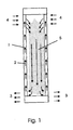
- a heat pipe comprises a sealed tube (1) containing a wick (2) and a working fluid.
- the working fluid evaporates to form vapour (5) at heat source (4) and moves to the heat sink (3) where it condenses.
- the wick then returns the condensed liquid to the heat source (4) by capillary action.
- a typical cool cabinet comprises an insulated cabinet (15) with a transparent or open front. At the bottom of the cabinet are an evaporator (10) and a fan (11). Food is stored on shelves (12). In use the fan (11) blows air over evaporator (10) which cools the air and cold air e.g. at approximately -5°C passes over the back of the shelves in a duct (14) and over the food as shown to cool the food. The food is warmed by radiant heat, which is then transferred to the cooling air, which is recirculated over the evaporator to cool it.
- the cabinet (21), evaporator (22) and fan (23) are as in fig. 2, but the shelves are replaced by shelves (20) incorporating a heat pipe, shown in detail in fig. 4.
- the ends of the heat pipes (20a) protrude through the back of the display section into duct through which cooled air from the evaporator passes.
- the heat pipe removes heat from the food on shelves (20) and so aids the convective cooling effect.
- the air is recirculated as in fig. 2.
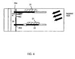
- the shelves (20) incorporating a heat pipe (23) have food (21) placed on them. Heat from the food is conducted by the heat pipe to the back of the heat pipe (20a), which is in the cold airflow from evaporator (22). The heat pipe rapidly conducts heat from the food to the cold part of the heat pipe (20a) and thus aids the convective cooling of the food.
Landscapes
- Engineering & Computer Science (AREA)
- Physics & Mathematics (AREA)
- Thermal Sciences (AREA)
- Chemical & Material Sciences (AREA)
- Combustion & Propulsion (AREA)
- Mechanical Engineering (AREA)
- General Engineering & Computer Science (AREA)
- Devices That Are Associated With Refrigeration Equipment (AREA)
- Freezers Or Refrigerated Showcases (AREA)
- Glass Compositions (AREA)
- Yarns And Mechanical Finishing Of Yarns Or Ropes (AREA)
- Crystals, And After-Treatments Of Crystals (AREA)
Abstract
Description
- The present invention relates to a method and equipment for keeping articles, particularly foods, cold.
- When food is displayed which has to be kept cool or cold it can be displayed in a refrigerated cabinet which has an open or glass or transparent plastic front. In conventional cabinets the food is displayed on shelves or decks and is cooled by cold air supplied from within the cabinet. The air is circulated through the cabinet using fans and the bulk of the air is directed into the display area as a jet which forms an air curtain across the cabinet opening. The air is then recirculated within the cabinet where it is cooled by a plate fin and tube heat exchanger containing a low temperature refrigerant with a saturated refrigerant temperature of approximately -7°C. The evaporator is normally in counterflow with the air, which enters the evaporator at approximately 5°C and leaves at approximately -5°C, the exact temperatures will vary with the make and type of cabinet the temperature variations may be for example ± 3K.
- It has been found that, in practice it is difficult to maintain display cabinets at low temperatures e.g. below 5°C and as result food is stored on display at higher temperatures. This is because convection is, however not an effective cooling mechanism. This is due in part to the low heat transfer coefficient caused by low velocity air, but it is also because the air close to the cabinet front is warm due to air ingress. As a result convective cooling systems maintain a large spread of temperatures within the cabinet, with the higher temperature food near to the front opening. Lower food temperatures are achievable with conventional systems, however, this requires the use of lower temperature air, and because of the large temperature spread with the cabinet, low temperature air will lead to localised freezing of some food products and frost damage to food.
- Providing more powerful cooling systems, as well as being expensive can lead to local freezing and ice formation so that defrosting is required.
- Although the food is normally delivered to the cabinet at the required food storage temperature, cooling is required to offset gains to the food which are purely a result of radiant interchange between the food and the external supermarket/shop environment. The cooling load necessary to offset these gains is only a fraction of that delivered to the cabinet. At best this low heat transfer rate results in excessive energy use, high equipment costs and reduces food shelf life. At worst, the low efficiency can result in failure to meet food hygiene temperatures which can present food safety issues.
- It has been proposed to provide significant additional cooling to the food by positioning the food directly in contact with a cold base. This was achieved by siting the food on a base in contact with the evaporator. Significantly increasing heat transfer to the food in this way enables the cabinet to operate more efficiently and results in significant reductions in energy consumption, as well as improvements in food quality/safety. However as most chilled cabinets utilise adjustable shelving, producing conduction by sitting the food shelves onto a fixed evaporator surface is not a practical option.
- French Patent FR-A-2 755 359 discloses the use of heat pipe to cool food placed on a shelf by incorporating the heat pipe in the shelf. However this patent does not disclose the use a heat pipe to aid the convective cooling of food stored in a cool cabinet.
- We have now devised a method of providing conductive cooling to the food but still maintaining adjustable shelving.
- According to the invention there is provided a method of cooling food in a cabinet in which the food is positioned on a shelf or deck in the cabinet which shelf or deck incorporates a heat pipe, at least a part of which heat pipe is cooled and heat is conducted from the food by conduction by the cooling effect of the heat pipe and the food placed on the said shelf or deck is also cooled by a convective cooling means.
- The invention also provides equipment for keeping food cool which equipment which comprises a cabinet incorporating at least one shelf or deck on which food can be placed, in which the shelf or deck incorporates a heat pipe and there is a cooling means to cool at least part of the heat pipe and, when food is positioned on the shelf, there is heat conduction from the food to the shelf and in which there is also a convective cooling means to cool food placed on the said shelf or deck.
- The heat pipe is used because it is a passive, highly efficient heat transfer mechanism with a reported conductivity equivalent to approximately 500 times that of copper. Heat pipes are robust, simple and maintenance free devices that operate isothermally, require no pumping power and can transfer heat over a long distance. Heat pipes are described in an Article by Dunn P.D. and Reay D.A. (1994) in Heat Pipes 4th Edition pp 1-3, 100, Elsevier Science Ltd. Oxford UK.
- In use the food is placed on the shelf which incorporates the heat pipe and preferably the end of the heat pipe at the rear of the shelf is cooled e.g. by blowing cold air over the pipe from the cabinet's cooling system. The heat pipe cools the shelf and keeps the food cool by conduction from the shelf to the food.
- The shelf can comprise one flat heat pipe or a series of connected heat pipes.
- Preferably the cooling means is a conventional cooling system in which air is recirculated within the cabinet where it is cooled by a plate fin and tube heat exchanger containing a low temperature refrigerant e.g. with a saturated refrigerant temperature of approximately -7°C. The evaporator is in counterflow with the air, which enters the evaporator at approximately 5°C and leaves at approximately -5°C.
- In use in a cabinet for keeping food cool there is conventional convective cooling which is supplemented by conductive heat transfer provided by a shelf cooling mechanism incorporating a heat pipe so that the shelf is used to display the food and also to transfer heat from it to the cabinet supply air duct.
- Preferably the shelf is constructed as a heat pipe and positioning through the display area back plate into the supply air duct, which is at approximately-5°C.
- There can be phase change materials incorporated in the shelves or adjacent the shelves so as to provide extra cooling capacitance in case of power or other failure so that the change of phase provides a cooling effect in the case of such failure.
- The invention can be applied to conventional cabinets by replacing the existing shelves with shelves incorporating heat pipe or pipes and it is a feature of the invention that it can contribute to lower core food temperatures e.g. of up to approximately 2.5 to 3K which would lead to significant reductions in energy and capital costs as well as improvements in food quality and shelf life. Furthermore using heat pipe shelving could result in avoiding electric defrost, which is energy intensive.
- The invention can be used with any type of cabinet e.g. open fronted, closed cabinets and all types of frozen food cabinets.
- The invention is described in the accompanying drawings in which: -
- Fig. 1 shows the principle of operation of the simple heat pipe
- Fig. 2 shows a conventional cool cabinet
- Fig. 3 shows a cabinet incorporating the invention and
- Fig. 4 shows a shelf in detail
- Referring to fig. 1 a heat pipe comprises a sealed tube (1) containing a wick (2) and a working fluid. When heat is applied, the working fluid evaporates to form vapour (5) at heat source (4) and moves to the heat sink (3) where it condenses. The wick then returns the condensed liquid to the heat source (4) by capillary action.
- Referring to fig. 2 a typical cool cabinet comprises an insulated cabinet (15) with a transparent or open front. At the bottom of the cabinet are an evaporator (10) and a fan (11). Food is stored on shelves (12). In use the fan (11) blows air over evaporator (10) which cools the air and cold air e.g. at approximately -5°C passes over the back of the shelves in a duct (14) and over the food as shown to cool the food. The food is warmed by radiant heat, which is then transferred to the cooling air, which is recirculated over the evaporator to cool it.
- Referring to fig. 3 the cabinet (21), evaporator (22) and fan (23) are as in fig. 2, but the shelves are replaced by shelves (20) incorporating a heat pipe, shown in detail in fig. 4. The ends of the heat pipes (20a) protrude through the back of the display section into duct through which cooled air from the evaporator passes. As well as the cooling effect of the air, the heat pipe removes heat from the food on shelves (20) and so aids the convective cooling effect. The air is recirculated as in fig. 2.
- Referring to fig. 4 the shelves (20) incorporating a heat pipe (23) have food (21) placed on them. Heat from the food is conducted by the heat pipe to the back of the heat pipe (20a), which is in the cold airflow from evaporator (22). The heat pipe rapidly conducts heat from the food to the cold part of the heat pipe (20a) and thus aids the convective cooling of the food.
Claims (10)
- Equipment for keeping food cool which equipment comprises a cabinet (21) incorporating at least one shelf or deck (20) on which food can be placed, in which the shelf or deck (20) incorporates a heat pipe (23) and there is a cooling means to cool at least part (20a) of the heat pipe so that, when food is positioned on the shelf, there is heat conduction from the food to the shelf characterised in that there is also a convective cooling means to cool food placed on the said shelfor deck.
- Equipment as claimed in claim 1 characterised in that there are cooling means to cool the end of the heat pipe (20a) at the rear of the shelf or deck remote from the front of the cabinet.
- Equipment as claimed in claim 2 characterised in that the cooling means are means for blowing cold air over the heat pipe from a cooling system (23).
- Equipment as claimed in claim 3 characterised in that the cabinet has a back plate behind which is a duct for supply of cool air, the said shelf or deck is constructed as a heat pipe and the end of the heat pipe passes through the cabinet back plate into the duct for the supply for cold air.
- Equipment as claimed in any one of the preceding claims characterised in that there are means to recirculate the air within the cabinet and the cooling means is a tube heat exchanger containing a low temperature refrigerant incorporating an evaporator which evaporator is in counterflow with the air.
- Equipment as claimed in any one of the preceding claims characterised in that phase change materials are incorporated in the shelves or decks or adjacent the shelves or decks so as to provide extra cooling capacitance.
- Equipment as claimed in any one of the preceding claims characterised in that the shelving is adjustable.
- A method of cooling food in a cabinet (21) in which the food is positioned on a shelf or deck (20) in the cabinet which shelf or deck incorporates a heat pipe at least a part of which heat pipe (20a) is cooled and heat is conducted from the food by conduction by the cooling effect of the heat pipe characterised in that the food placed on the said shelf or deck is also cooled by a convective cooling means.
- A method as claimed in claim 8 for cooling food characterised in that the food is placed on the shelf or deck (20) which incorporates the heat pipe and the end of the heat pipe at the rear of the shelf or deck remote from the front of the cabinet (20a) is cooled by blowing cold air over the pipe from a cooling means in the cabinet (22).
- A method as claimed in claim 8 or 9 characterised in that phase change materials incorporated in the shelves or decks or adjacent the shelves or decks provide extra cooling capacitance.
Applications Claiming Priority (3)
| Application Number | Priority Date | Filing Date | Title |
|---|---|---|---|
| GB0020171 | 2000-08-17 | ||
| GBGB0020171.5A GB0020171D0 (en) | 2000-08-17 | 2000-08-17 | Cooling method |
| PCT/GB2001/003675 WO2002015752A1 (en) | 2000-08-17 | 2001-08-16 | Cooling method |
Publications (2)
| Publication Number | Publication Date |
|---|---|
| EP1309261A1 EP1309261A1 (en) | 2003-05-14 |
| EP1309261B1 true EP1309261B1 (en) | 2007-01-03 |
Family
ID=9897722
Family Applications (1)
| Application Number | Title | Priority Date | Filing Date |
|---|---|---|---|
| EP01956702A Expired - Lifetime EP1309261B1 (en) | 2000-08-17 | 2001-08-16 | Cooling method |
Country Status (8)
| Country | Link |
|---|---|
| US (2) | US20040011077A1 (en) |
| EP (1) | EP1309261B1 (en) |
| JP (1) | JP2004506463A (en) |
| AT (1) | ATE349935T1 (en) |
| AU (1) | AU2001278621A1 (en) |
| DE (1) | DE60125779T2 (en) |
| GB (1) | GB0020171D0 (en) |
| WO (1) | WO2002015752A1 (en) |
Families Citing this family (16)
| Publication number | Priority date | Publication date | Assignee | Title |
|---|---|---|---|---|
| AR036872A1 (en) | 2001-08-13 | 2004-10-13 | Du Pont | ANTRANILAMIDE COMPOSITE, COMPOSITION THAT INCLUDES IT AND METHOD FOR CONTROLLING AN INVERTEBRATE PEST |
| TWI283164B (en) | 2001-09-21 | 2007-07-01 | Du Pont | Anthranilamide arthropodicide treatment |
| WO2007053148A1 (en) * | 2005-11-04 | 2007-05-10 | Carrier Corroration | Refrigerated merchandiser and shelf therefor |
| DE102007042240B3 (en) * | 2007-09-06 | 2009-02-05 | Caverion Gmbh | Method and device for air conditioning a showcase |
| JP5241414B2 (en) * | 2008-09-30 | 2013-07-17 | 三洋電機株式会社 | Image display device |
| MX2011004141A (en) | 2008-10-17 | 2011-05-24 | Nestec Sa | Whey protein compositions, methods and uses. |
| EP2715257A1 (en) * | 2011-05-26 | 2014-04-09 | Viking Cold Solutions, Inc. | Cold storage rack system with overhead pcm support |
| US20130002099A1 (en) * | 2011-06-30 | 2013-01-03 | Pepsico, Inc. | Modular Refrigerated Merchandise Display System |
| US9532661B2 (en) | 2011-06-30 | 2017-01-03 | Pepsico, Inc. | Modular refrigerated merchandise display system |
| US9016070B2 (en) | 2012-09-14 | 2015-04-28 | Whirlpool Corporation | Phase change materials for refrigeration and ice making |
| US10240850B1 (en) * | 2013-03-15 | 2019-03-26 | Joseph P. Stine | Supplemental refrigeration heat sink and related systems and methods |
| US20150297000A1 (en) * | 2014-04-22 | 2015-10-22 | Heatcraft Refrigeration Products Llc | Refrigerated Display Case with Temperature Controlled Shelves |
| CN104223854A (en) * | 2014-09-16 | 2014-12-24 | 湖南大学 | Novel refrigerated display cabinet |
| GB2531365B (en) * | 2014-12-23 | 2017-01-11 | Flint Eng Ltd | Heat transfer apparatus |
| MX2023000921A (en) * | 2022-01-19 | 2023-07-20 | Hussmann Corp | Hybrid shelf with embedded thermal spreader. |
| US20250027725A1 (en) * | 2023-07-21 | 2025-01-23 | Trane Technologies Life Sciences Llc | Systems and methods for heat transfer using heat pipes |
Family Cites Families (15)
| Publication number | Priority date | Publication date | Assignee | Title |
|---|---|---|---|---|
| JPS4887779A (en) * | 1972-02-01 | 1973-11-17 | ||
| US4340111A (en) * | 1972-10-04 | 1982-07-20 | Skala Stephen F | Evaporative cooling of containers in a pressure vessel |
| US5846703A (en) * | 1990-05-15 | 1998-12-08 | Diatron Corporation | Fluorescence immunoassays using fluorescent dyes free of aggregation and serum binding |
| US5201364A (en) * | 1990-09-17 | 1993-04-13 | Tippmann Vincent P | Apparatus for heating and cooling food articles having removable plates with fluid sealed therein |
| US5404935A (en) * | 1991-05-31 | 1995-04-11 | Beltec International | Cabinet-style apparatus for transferring heat to food and cooling food |
| CA2094673C (en) * | 1992-10-01 | 2000-10-24 | Joseph R. Lovin | Hydronic cooling of particle accelerator window |
| US5797445A (en) * | 1992-11-23 | 1998-08-25 | Standex International Corporation | Refrigerated rethermalization cart |
| FR2701368B1 (en) * | 1993-02-12 | 1995-05-24 | Andre Renard | Removable refrigerated units. |
| EP0848800B1 (en) * | 1995-09-08 | 2000-12-13 | René Grandi | Mobile trolley for distributing hot and cold meal trays having warming-up and refrigeration capacities with self-contained reserve and ... |
| FR2755359B1 (en) * | 1996-11-05 | 1999-02-05 | Italinnova Sas | COLD STORAGE CABINET WITH REHABILITATION OF COOKED DISHES ON MEAL TRAYS |
| FR2763117B1 (en) * | 1997-05-12 | 1999-08-13 | Italinnova Sas | INSTALLATION FOR COLD STORAGE WITH LOCAL HEATING OF MEALS ON MEAL TRAYS |
| FR2766148B1 (en) * | 1997-07-16 | 1999-09-17 | Soc D Const De Materiel Metall | TROLLEY COMPRISING A COOLING DEVICE THAT CAN BE INSTALLED AT ANY TIME CHOSEN BY THE USER AND METHOD FOR PROVIDING A HEATED FOOD |
| FR2778733B1 (en) * | 1998-05-12 | 2000-08-18 | Austria Haus Technik Aktienges | SHELF-EXCHANGERS FOR SALE REFRIGERATED FURNITURE AND REFRIGERATED FURNITURE USED BY SUCH SHELVES |
| US6310772B1 (en) * | 1999-09-02 | 2001-10-30 | Special Product Company | Enclosure for telecommunications equipment |
| FR2805443B1 (en) * | 2000-02-24 | 2002-07-19 | Italinnova Sas | DEVICE FOR STORING AND HEATING MEAL TRAYS WITH MODULAR HOT AND COLD ZONES |
-
2000
- 2000-08-17 GB GBGB0020171.5A patent/GB0020171D0/en not_active Ceased
-
2001
- 2001-08-16 EP EP01956702A patent/EP1309261B1/en not_active Expired - Lifetime
- 2001-08-16 WO PCT/GB2001/003675 patent/WO2002015752A1/en not_active Ceased
- 2001-08-16 DE DE60125779T patent/DE60125779T2/en not_active Expired - Fee Related
- 2001-08-16 US US10/362,383 patent/US20040011077A1/en not_active Abandoned
- 2001-08-16 JP JP2002520671A patent/JP2004506463A/en not_active Withdrawn
- 2001-08-16 AT AT01956702T patent/ATE349935T1/en not_active IP Right Cessation
- 2001-08-16 AU AU2001278621A patent/AU2001278621A1/en not_active Abandoned
-
2006
- 2006-08-16 US US11/505,078 patent/US20060278369A1/en not_active Abandoned
Also Published As
| Publication number | Publication date |
|---|---|
| JP2004506463A (en) | 2004-03-04 |
| DE60125779D1 (en) | 2007-02-15 |
| WO2002015752A1 (en) | 2002-02-28 |
| ATE349935T1 (en) | 2007-01-15 |
| US20060278369A1 (en) | 2006-12-14 |
| GB0020171D0 (en) | 2000-10-04 |
| AU2001278621A1 (en) | 2002-03-04 |
| EP1309261A1 (en) | 2003-05-14 |
| DE60125779T2 (en) | 2007-05-24 |
| US20040011077A1 (en) | 2004-01-22 |
Similar Documents
| Publication | Publication Date | Title |
|---|---|---|
| US20040011077A1 (en) | Cooling method | |
| US4505131A (en) | Insulated cabinet | |
| US3100970A (en) | Thermoelectrically refrigerated apparatus | |
| US6418729B1 (en) | Domestic refrigerator with peltier effect, heat accumulators and evaporative thermosyphons | |
| US20050109040A1 (en) | Merchandising cooler having large packout and small footprint | |
| US20090001861A1 (en) | Retail in-cabinet refrigeration and storage unit | |
| CN101443612A (en) | Thermoelectric defrosting system | |
| US20100192600A1 (en) | Air cooled display case shelf | |
| EP1880154A1 (en) | Improved refrigeration apparatus | |
| CN113503666A (en) | Air curtain freezer | |
| EP2092861B1 (en) | Sales furniture | |
| US7975492B2 (en) | Thermoelectric cooling for a refrigerated display case | |
| Maidment et al. | An investigation of a novel cooling system for chilled food display cabinets | |
| EP3865798B1 (en) | Display assembly and method for operating the same | |
| CN216080516U (en) | Refrigerating cabinet | |
| JP3860238B2 (en) | Structure of refrigerated or refrigerated display cabinet | |
| JP2006189209A (en) | Refrigerator | |
| CN216754058U (en) | Low-temperature fresh-keeping display cabinet refrigerator for fresh food | |
| JP2006138552A (en) | Refrigerator | |
| EP4155623A1 (en) | Cabinet for refrigeration and storage of food products | |
| JP2957923B2 (en) | Showcase cooling method and cooling device | |
| JPH10318652A (en) | Flat type open showcase | |
| WO2019102252A1 (en) | Autonomous refrigerated island of semi-vertical cabinets and refrigeration method | |
| KR19990013133U (en) | Defrost heater installation structure of rich in showcase | |
| WO2006127094A2 (en) | A system and method for storing a product in a thermally stabilized state |
Legal Events
| Date | Code | Title | Description |
|---|---|---|---|
| PUAI | Public reference made under article 153(3) epc to a published international application that has entered the european phase |
Free format text: ORIGINAL CODE: 0009012 |
|
| 17P | Request for examination filed |
Effective date: 20030217 |
|
| AK | Designated contracting states |
Designated state(s): AT BE CH CY DE DK ES FI FR GB GR IE IT LI LU MC NL PT SE TR |
|
| AX | Request for extension of the european patent |
Extension state: AL LT LV MK RO SI |
|
| 17Q | First examination report despatched |
Effective date: 20041029 |
|
| GRAP | Despatch of communication of intention to grant a patent |
Free format text: ORIGINAL CODE: EPIDOSNIGR1 |
|
| GRAS | Grant fee paid |
Free format text: ORIGINAL CODE: EPIDOSNIGR3 |
|
| RIN1 | Information on inventor provided before grant (corrected) |
Inventor name: MAIDMENT, GRAEME, GREGERY |
|
| GRAA | (expected) grant |
Free format text: ORIGINAL CODE: 0009210 |
|
| AK | Designated contracting states |
Kind code of ref document: B1 Designated state(s): AT BE CH CY DE DK ES FI FR GB GR IE IT LI LU MC NL PT SE TR |
|
| PG25 | Lapsed in a contracting state [announced via postgrant information from national office to epo] |
Ref country code: FI Free format text: LAPSE BECAUSE OF FAILURE TO SUBMIT A TRANSLATION OF THE DESCRIPTION OR TO PAY THE FEE WITHIN THE PRESCRIBED TIME-LIMIT Effective date: 20070103 Ref country code: CH Free format text: LAPSE BECAUSE OF FAILURE TO SUBMIT A TRANSLATION OF THE DESCRIPTION OR TO PAY THE FEE WITHIN THE PRESCRIBED TIME-LIMIT Effective date: 20070103 Ref country code: AT Free format text: LAPSE BECAUSE OF FAILURE TO SUBMIT A TRANSLATION OF THE DESCRIPTION OR TO PAY THE FEE WITHIN THE PRESCRIBED TIME-LIMIT Effective date: 20070103 Ref country code: DK Free format text: LAPSE BECAUSE OF FAILURE TO SUBMIT A TRANSLATION OF THE DESCRIPTION OR TO PAY THE FEE WITHIN THE PRESCRIBED TIME-LIMIT Effective date: 20070103 Ref country code: LI Free format text: LAPSE BECAUSE OF FAILURE TO SUBMIT A TRANSLATION OF THE DESCRIPTION OR TO PAY THE FEE WITHIN THE PRESCRIBED TIME-LIMIT Effective date: 20070103 Ref country code: NL Free format text: LAPSE BECAUSE OF FAILURE TO SUBMIT A TRANSLATION OF THE DESCRIPTION OR TO PAY THE FEE WITHIN THE PRESCRIBED TIME-LIMIT Effective date: 20070103 |
|
| REG | Reference to a national code |
Ref country code: GB Ref legal event code: FG4D |
|
| REF | Corresponds to: |
Ref document number: 60125779 Country of ref document: DE Date of ref document: 20070215 Kind code of ref document: P |
|
| REG | Reference to a national code |
Ref country code: IE Ref legal event code: FG4D |
|
| PG25 | Lapsed in a contracting state [announced via postgrant information from national office to epo] |
Ref country code: SE Free format text: LAPSE BECAUSE OF FAILURE TO SUBMIT A TRANSLATION OF THE DESCRIPTION OR TO PAY THE FEE WITHIN THE PRESCRIBED TIME-LIMIT Effective date: 20070403 |
|
| PG25 | Lapsed in a contracting state [announced via postgrant information from national office to epo] |
Ref country code: ES Free format text: LAPSE BECAUSE OF FAILURE TO SUBMIT A TRANSLATION OF THE DESCRIPTION OR TO PAY THE FEE WITHIN THE PRESCRIBED TIME-LIMIT Effective date: 20070414 |
|
| ET | Fr: translation filed | ||
| PG25 | Lapsed in a contracting state [announced via postgrant information from national office to epo] |
Ref country code: PT Free format text: LAPSE BECAUSE OF FAILURE TO SUBMIT A TRANSLATION OF THE DESCRIPTION OR TO PAY THE FEE WITHIN THE PRESCRIBED TIME-LIMIT Effective date: 20070604 |
|
| NLV1 | Nl: lapsed or annulled due to failure to fulfill the requirements of art. 29p and 29m of the patents act | ||
| REG | Reference to a national code |
Ref country code: CH Ref legal event code: PL |
|
| PLBE | No opposition filed within time limit |
Free format text: ORIGINAL CODE: 0009261 |
|
| STAA | Information on the status of an ep patent application or granted ep patent |
Free format text: STATUS: NO OPPOSITION FILED WITHIN TIME LIMIT |
|
| 26N | No opposition filed |
Effective date: 20071005 |
|
| PG25 | Lapsed in a contracting state [announced via postgrant information from national office to epo] |
Ref country code: BE Free format text: LAPSE BECAUSE OF FAILURE TO SUBMIT A TRANSLATION OF THE DESCRIPTION OR TO PAY THE FEE WITHIN THE PRESCRIBED TIME-LIMIT Effective date: 20070103 |
|
| PG25 | Lapsed in a contracting state [announced via postgrant information from national office to epo] |
Ref country code: MC Free format text: LAPSE BECAUSE OF NON-PAYMENT OF DUE FEES Effective date: 20070831 Ref country code: GR Free format text: LAPSE BECAUSE OF FAILURE TO SUBMIT A TRANSLATION OF THE DESCRIPTION OR TO PAY THE FEE WITHIN THE PRESCRIBED TIME-LIMIT Effective date: 20070404 |
|
| PG25 | Lapsed in a contracting state [announced via postgrant information from national office to epo] |
Ref country code: IE Free format text: LAPSE BECAUSE OF NON-PAYMENT OF DUE FEES Effective date: 20070816 |
|
| PGFP | Annual fee paid to national office [announced via postgrant information from national office to epo] |
Ref country code: DE Payment date: 20080828 Year of fee payment: 8 |
|
| PGFP | Annual fee paid to national office [announced via postgrant information from national office to epo] |
Ref country code: FR Payment date: 20080814 Year of fee payment: 8 Ref country code: IT Payment date: 20080821 Year of fee payment: 8 |
|
| PGFP | Annual fee paid to national office [announced via postgrant information from national office to epo] |
Ref country code: GB Payment date: 20080813 Year of fee payment: 8 |
|
| PG25 | Lapsed in a contracting state [announced via postgrant information from national office to epo] |
Ref country code: CY Free format text: LAPSE BECAUSE OF FAILURE TO SUBMIT A TRANSLATION OF THE DESCRIPTION OR TO PAY THE FEE WITHIN THE PRESCRIBED TIME-LIMIT Effective date: 20070103 |
|
| PG25 | Lapsed in a contracting state [announced via postgrant information from national office to epo] |
Ref country code: LU Free format text: LAPSE BECAUSE OF NON-PAYMENT OF DUE FEES Effective date: 20070816 |
|
| PG25 | Lapsed in a contracting state [announced via postgrant information from national office to epo] |
Ref country code: TR Free format text: LAPSE BECAUSE OF FAILURE TO SUBMIT A TRANSLATION OF THE DESCRIPTION OR TO PAY THE FEE WITHIN THE PRESCRIBED TIME-LIMIT Effective date: 20070103 |
|
| GBPC | Gb: european patent ceased through non-payment of renewal fee |
Effective date: 20090816 |
|
| REG | Reference to a national code |
Ref country code: FR Ref legal event code: ST Effective date: 20100430 |
|
| PG25 | Lapsed in a contracting state [announced via postgrant information from national office to epo] |
Ref country code: FR Free format text: LAPSE BECAUSE OF NON-PAYMENT OF DUE FEES Effective date: 20090831 Ref country code: DE Free format text: LAPSE BECAUSE OF NON-PAYMENT OF DUE FEES Effective date: 20100302 |
|
| PG25 | Lapsed in a contracting state [announced via postgrant information from national office to epo] |
Ref country code: GB Free format text: LAPSE BECAUSE OF NON-PAYMENT OF DUE FEES Effective date: 20090816 |
|
| PG25 | Lapsed in a contracting state [announced via postgrant information from national office to epo] |
Ref country code: IT Free format text: LAPSE BECAUSE OF NON-PAYMENT OF DUE FEES Effective date: 20090816 |