EP1309188A2 - Method for calibrating a film scanner - Google Patents
Method for calibrating a film scanner Download PDFInfo
- Publication number
- EP1309188A2 EP1309188A2 EP02079320A EP02079320A EP1309188A2 EP 1309188 A2 EP1309188 A2 EP 1309188A2 EP 02079320 A EP02079320 A EP 02079320A EP 02079320 A EP02079320 A EP 02079320A EP 1309188 A2 EP1309188 A2 EP 1309188A2
- Authority
- EP
- European Patent Office
- Prior art keywords
- film
- printing densities
- print material
- digital signal
- telecine
- Prior art date
- Legal status (The legal status is an assumption and is not a legal conclusion. Google has not performed a legal analysis and makes no representation as to the accuracy of the status listed.)
- Withdrawn
Links
Images



Classifications
-
- H—ELECTRICITY
- H04—ELECTRIC COMMUNICATION TECHNIQUE
- H04N—PICTORIAL COMMUNICATION, e.g. TELEVISION
- H04N5/00—Details of television systems
- H04N5/222—Studio circuitry; Studio devices; Studio equipment
- H04N5/253—Picture signal generating by scanning motion picture films or slide opaques, e.g. for telecine
Definitions
- the invention relates generally to improvements in the field of film scanning, and in particular to improvements in the transfer of motion picture film to a digital signal that is especially adapted for film recording.
- an original motion picture negative film is exposed during a camera exposure operation 10, developed into a processed camera negative 12 and subsequently processed in one of several ways.
- an optical printing process 18 and a film scanning process 20.
- the optical printing process may be practiced in several ways in order to optically transfer the image data to a print material.
- the optical transfer is direct; that is, the color negative film 12 is optically printed onto another photosensitive material, e.g., a release print material 22 such as Eastman Color Print Film 5386TM, to produce a color positive image suitable for projection.
- the camera negative 12 may be converted into an interpositive 14, which is a positive image optically produced on a negative copying material with the same contrast and the same extended range of the scene as the camera negative.
- either element 12 or 14 then constitutes the photographic film element 16 identified in Figure 1, which is subsequently processed.
- the optical transfer of the original image data to a print material is indirect; that is, the interpositive 14 is used to optically produce numerous duplicate negatives 24, which are then optically printed (process 26) onto release prints 28, which may also be Eastman Color Print Film 5386TM.
- the color negative film information (camera negative 12) or the color print film information (interpositive 14) is transferred into a video signal using a telecine transfer device in the telecine scanning process 20.
- the interpositive is a negative copying material that is used to produce a positive with the same contrast as the original negative and the same extended range of the scene; this element is then used in the trade as the element to scan on the telecine device without risking harm to the original negative.
- Various types of telecine transfer devices are described in Engineering Handbook, E.O. Fritts, Ed., 8 th edition, National Association of Broadcasters, 1992, Chapter 5.8, pp. 933-946, the disclosure of which is incorporated by reference.
- CCD sensors include either an area array scanner (captures the full frame at once) or a linear line scanner (the film is transported across a line array of sensors and the total image is then a reconstruction of all the lines to give an area image).
- Telecine devices scan each negative or positive film frame transforming the transmittance at each pixel of an image into a voltage. The signal processing then inverts the electrical signal in the case of a transfer made from a negative film in order to render a positive image.
- the signal is carefully amplified and modulated, and fed into a cathode ray tube monitor 30 to display the image, and/or recorded onto magnetic tape for storage in a recording stage 32.
- the output of the telecine scanning process 20 may be applied to a film recording stage 34, which produces a negative film 36 that can be optically printed out as a release print.
- the monitor 30 is typically a high definition (HD) monitor with the data provided from the telecine scanning process 20 incorporating the characteristics of the monitor such that the video image is pleasing to the operator.
- HD high definition
- the telecine transfer device only a restricted range of the total image on the film element 16 is used (i.e., compressed into the tonal range of the monitor). If a video tape is desired from the video recording process 32, the data associated with the image displayed on the monitor is written to digital (or analog) tape.
- the telecine device has an output data pathway which includes one dimensional look up tables (1D LUTs) 38 that transform a video tone scale to a more film like tone scale such that the resulting negative 36 produced will print onto a photographic print element 28 and look at least somewhat like a film system image.
- the video monitor image usually will not match the final print image in tone scale and color reproduction.
- the digital data acquired in the telecine scanning process 20 only has the restricted range of the initial video range capture. If the client desires changes to the final look, the operator can only modify the data obtained. If there was information on the photographic film element 16 outside of the range initially captured, then it is not represented in the data and cannot be used. An example of this could be an interior scene with a person sitting at a desk with an outside window in the background. In a normal telecine transfer, the very high exposure of the outside window relative to the proper lightness of the interior foreground will show up as a very light area without much detail. However, the film element has considerable detail in this area but without advanced technical techniques it cannot be displayed on the HD monitor.
- the extended range can be captured in a second scan through the telecine scanning process 20 with a different setup that maximizes the high exposure area.
- the two scans can then be merged with advanced digital techniques.
- One drawback of this technique is that the extended range that needs to be captured must be known at the time of the original scan, otherwise a future new scan is required with added cost.
- the desired transfer would capture the entire extended range of the negative, in the current system the HD monitor would be unable to effect correct tone scale and color reproduction and thus would be useless as a creative display device.
- some postproduction facilities use a technique that tries to capture the complete negative range.
- the highest density on the negative is assigned to the highest video level and the lowest density on the negative is assigned to a low video level (usually not the full low to high range available in the bit depth of the transfer).
- This data can then be color corrected on another device, which inputs data and allows digital manipulation to give an image on a monitor that is pleasing to the client.
- another device usually another computer system, is employed in an attempt to show a film look from the data to validate the image content before committing to film recording.
- a method of transferring an image recorded on a photographic film to a digital signal, using a film scanning device that generates scan data representative of the digital signal comprises the steps of calibrating the film scanning device in relation to printing densities and scanning the photographic film with the film scanning device to produce scan data that represents printing densities.
- the scan data represents printing densities which when written out to the film recorder will produce printing densities of the output film onto the target print material that are identical to the printing densities of the same photographic film optically transferred onto the target print material.
- the present invention thus refers to a method of capturing the full content of a photographic element on a telecine scanning device.
- the advantage is that the resulting data can be used as input to a film-recording device without operator intervention to produce a negative, which will result in a print that matches a print from the original negative.
- the need for color grading on a scene-to-scene basis during the film scanning process is avoided.
- the postproduction data-to-data manipulation is usually a computer disk-to-disk operation, and in this case the full range of the scanned film element is available in one scan to achieve the desired look of the creative person directing the color transformation.
- CTRs cathode ray tubes
- electronic sensors are well known, the present description will be directed in particular to elements forming part of, or cooperating more directly with, the calibration technique in accordance with the present invention. Elements not specifically shown or described herein may be selected from those known in the art.
- the data generally used in the trade for film recording is a 10-bit log format. This is not just a mathematical logarithm but also a precise 10-bit digital representation of the negative's printing density.
- printing density is a reference to a density metric similar to the industry standard Status-M density. In this discussion both Status-M and printing density will refer to three integral red, green and blue channels.
- Integral Density - Log (Integral Transmittance).
- Integral Transmittance metric is a measure of the degree that an element alters the effective intensity of a light source.
- the mathematical computation of the integral transmittance of a photographic element such as a color negative is dependant on the spectral transmittance curve (transmittance at predefined wavelength increments, i.e., 10nm) of the element to be measured as well as the spectral power distribution of the light source and the spectral sensitivity of the detecting device.
- the red integral Status-M transmittance is the sum of the wavelength-by-wavelength products of the spectral transmittance of the film element and the normalized spectral power distribution of the light source and the normalized red spectral sensitivity of the Status-M detecting device.
- the red integral printing density transmittance is the sum of the wavelength-by-wavelength products of the spectral transmittance of the film element and the normalized spectral power distribution of the printing light source (motion picture film printer light source spectral distribution) and the normalized red spectral sensitivity of the print film spectral sensitivity.
- the green and blue channels are calculated in similar fashion.
- a Status-M density is a standard traceable to a standards reference document.
- a printing density is really a density representation as to how the photographic print element "sees" the dyes of the film element and predicts the independent red, green and blue channel attenuation in the printing process. It is clear that for any specific Status-M density of a particular film element there is an infinite number of sets of printing densities that depend on the printer lamp house and the characteristics of the print material.
- the 10-bit log format also provides for a scaling.
- a hypothetical film with a gamma of 0.5115 with a log exposure range of 4.0 (approx. 13.33 stops) could also be expressed in the complete code value range.
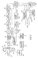
- a film transport 40 advances a motion picture film 41 at a substantially uniform speed through a film gate 42 from a supply reel 43 to a take up reel 44.
- a light source 45 generates a light beam that is directed through a circle to line converter 46 and focused upon a linear section of the film 41 in the film gate 42.
- the light is modulated by the image in the film 41 and transmitted through an objective lens 47 to a beam splitter 48, which transmits one portion of the light to an unsharp color sensor 49 and reflects the other portion to a high resolution luminance sensor 50.
- the color sensor 49 comprises three linear color arrays respectively sensitive to red, green and blue light.
- the luminance sensor 50 includes a linear array sensitized to light having a spectral composition approximating a luminance function.
- a sensor clock generator 51 provides a clock signal of appropriate frequency(s) for shifting the respective image signals from the output registers of the color sensor 49 and the luminance sensor 50.
- the luminance sensor 50 produces a full resolution signal according to the requirements of the high definition standard, or the film scanning standard, in use.
- Low resolution, or unsharp, color is provided from the color arrays comprising the color sensor 49, allowing the color photosites to be accordingly larger, which has the advantageous effect of increasing the signal-to-noise performance.
- the unsharp color sensor 49 provides three channels of color data to an analog-to-digital converter 52 and the luminance sensor 50 provides a high resolution data stream to another analog-to-digital converter 53. Because the three color arrays comprising the color sensor 49 are spaced in the direction of film motion, the fixed mis-registration of their output signals is corrected in color registration circuit 54.
- a color interpolation circuit 56 Since the digital color values represent lower resolution data than the digital luminance values, additional color values are generated in a color interpolation circuit 56 in both the horizontal and vertical directions. Meanwhile, high frequency detail is extracted from the luminance data by a detail extraction circuit 58 and added to each channel of color in an addition circuit 60, forming thereafter a full resolution, three channel, high definition color output signal.
- This high definition signal is applied to a digital processor 61, which can apply adjustments to the high resolution signal as determined from a telecine control section 62. A colorist would operate the telecine controls 62 to adjust the lift (dark areas), gain (highlights) and gamma (mid-tone) of the images produced by the high resolution signal.
- the control section 62 also includes an adjustment for the light level of the light source, which is communicated to a light source controller 63.
- the full resolution, three channel, high definition color output signal from the digital processor 61 is further processed either as a video output through an image store 64 or as a data output through a data interface 66.
- the image store 64 includes a first framestore 64a, a second framestore 64b and an interlace controller 64c for loading the high resolution data into one framestore while extracting high resolution video fields in interlace format from the other framestore.
- the output of the image store 64 can be applied, referring to Figure 1, to the monitor 30, after suitable adjustments for transfer characteristics by means of look-up tables (LUTs), or to a digital (or analog) video recording stage 32.
- the full content film scan data output from the data interface 66 may go to DVD, CD, VHS, an HD master, film output, and the like.
- the data output from the data interface 66 is applied to the film recording stage 34.
- the 1D LUTs 38 would not be used.
- Further details of the telecine and its operation can be found in commonly-assigned U.S. Patent No. 5,045,932, "Method and Apparatus for Generating a High Definition Electronic Signal from a Line Scan of a Color Signal", which is incorporated herein by reference.
- a calibration film element 80 (as shown in Figure 5) is manually run through the film gate and scanned.
- the actual, specific calibration of the telecine for a variety of filmstocks would use a plurality of calibration film elements, wherein each film element is used to calibrate the system for an accurate extended range printing density scan of a given film having given density-log exposure characteristics (one film element can be used for each set of films with similar characteristic curves).
- the specific characteristic of the calibration film element 80 is a neutral exposure onto the film element with the light balanced for the color temperature of the design criterion, e.g., whether designed for daylight vs. tungsten, of the film element.
- the exposure range is chosen from a standard set, in this case a 0 - 4.0 Log Exposure range (approx. 13.33 Stops) which on a film with a gamma of 0.55 reflects a printing density range of 2.20 which is slightly outside of the 2.046 printing density range of the 10-bit log format.
- the calibration film element 80 ordinarily includes a plurality of neutral patches ordered into a set, e.g., from light to dark; for instance, as specifically shown in Figure 5, the calibration film element 80 includes twenty-one patches 82 ordered at 0.2 log exposure increments for the 0 - 0.4 log exposure range.
- the arrangement in Figure 5 is shown without limitation, i.e., a greater or fewer number of patches may be used, their sizes and separation may vary, and they need not be in ascending (or descending) order of density.
- the movement of the calibration element through the telecine film gate could be automatic, rather than manual.
- the exposure range may be encoded in a greater bit depth; for example, if a 12-bit log format were adopted (0 - 4095 CV) and the current 0.002 printing density to CV scaling applied, then a printing density range of 8.19 could be accommodated. If, instead, the printing density to CV scaling was 0.001, then a printing density range of 4.095 could be accommodated. This would capture a 7.45 log exposure range on a gamma 0.55 film (24.8 Stops), far greater than is required for even advanced imaging.
- the current limitation of available technology is the linear bit depth of capture, which is 12-bits and which correlates well with the 10-bit Log format. When a greater linear bit depth of capture is available, at least 14-bits linear and preferably 16-bits linear would fit well with the 12-bit log format.
- Figure 3 shows the steps involved in generating the digital code value aims that are used in the calibration process.
- the calibration film element 80 described above is measured on a spectral instrument to determine the spectral transmittance curves for each of the patches of the calibration element (e.g., for the 0 - 4.0 Log Exposure calibration film element 80 shown in Figure 5 the usual exposure increment is 0.20 Log Exposure for a total of 21 patches).
- the obtained measurements are applied to a printing density aim calculation step 92 where the data is used as described above to calculate the printing density aims for the calibration, basically by summing, for each color, the wavelength-by-wavelength products of the spectral transmittance of the film element, the normalized spectral power distribution of the printing light source and the normalized spectral sensitivity of the print film spectral sensitivity. Then, in a conversion step 94, the printing density aims are converted to digital code value aims by, e.g., dividing through by 0.02 to obtain code values. In a storage step 96, the digital code value aims are stored in a storage associated with the digital processor 61 ( Figure 2).
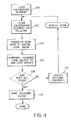
- FIG. 4 shows the steps involved in calibrating the telecine to the digital code value aims that were generated in the preliminary steps shown in Figure 3.
- the telecine device is first set into its center TAF (from Eastman Kodak Company's Telecine Analysis Film) setup mode.
- the TAF setting is a well-understood industry standard that is used to center the controls of a telecine device, and it sets the starting tone scale and color position to the TAF reference chart.
- the calibration film element 80 is loaded onto the telecine device in a loading step 100.
- a scanning step 102 the calibration film element 80 is scanned on the telecine and the scan data is saved. This scan data is then transferred into digital code values in a transfer step 104.
- a comparison step 106 the digital code values are compared to the digital aim code values, which have been calculated in the process shown in Figure 3 and stored. If the values are unequal (decision step 108), the calibration process initiates an adjustment 110 of the digital telecine controls 62 ( Figure 2).
- an experienced colorist manipulates the telecine primary controls 62.
- the goal is to adjust the telecine data signal so as to achieve the aim output code values of each patch of the calibration film element 80.
- the scan of the calibration film element 80 is repeated in the scanning step 102 and the subsequent process is repeated until the obtained code values (from the scan) are found to be equal (step 108) to the aim code values.
- the telecine control setups are saved in the storage step 112 and telecine transfer of a filmstock may commence.
- Each film type potentially requires a different calibration setup (assuming each film type has different film characteristics) that is stored and retrieved when that film type is being run on the telecine.
- the resulting plurality of calibration setups (at least one for every film type) can easily be managed by using metadata in the form of KeyKode (which are computer readable markings provided on the film that specifies the film type) to select the proper setup.
- the benefit of this invention is that a postproduction facility could have a single (or few) telecine devices which could scan very fast, without making color grading decisions, and the resulting data could go a disk-to-disk final color grading at a later time, and even at alternative sites.
- This procedure also lowers the effective transfer time, which minimizes the potential problem of dirt collection during transfer. Dirt removal from digital data elements is costly in time and money. The saving of time, money, flexibility and accuracy to film is unprecedented in motion picture postproduction.
Landscapes
- Engineering & Computer Science (AREA)
- Multimedia (AREA)
- Signal Processing (AREA)
- Projection-Type Copiers In General (AREA)
- Color Image Communication Systems (AREA)
- Color Television Image Signal Generators (AREA)
- Facsimiles In General (AREA)
Abstract
Description
Claims (9)
- A method of transferring an image recorded on a photographic film to a digital signal by using a film scanning device that generates scan data representative of the digital signal, said method comprising the steps of calibrating the film scanning device in relation to printing densities and scanning the photographic film with the film scanning device to produce scan data that represents printing densities.
- The method as claimed in claim 1 wherein the digital signal is used to drive a film recorder that exposes an output film that is subsequently printed onto a target print material, said scan data representing printing densities which when written out to the film recorder will produce printing densities of the output film onto the target print material that are identical to the printing densities of the same photographic film optically transferred onto the target print material.
- A method of transferring an image recorded on a photographic film to a digital signal by using a telecine scanning device that generates code values representative of the digital signal, wherein the telecine scanning device is calibrated in relation to printing densities and the scan data accordingly represents printing densities.
- The method as claimed in claim 3 wherein the code values are obtained by scanning the photographic film.
- The method as claimed in claim 3 wherein the photographic film is either a camera negative film or an intermediate film obtained from the camera negative film.
- The method as claimed in claim 3 wherein the digital signal drives a film recorder that exposes an output film that is subsequently printed onto a target print material, said code values representing printing densities which when written out to the film recorder will produce printing densities of the output film onto the target print material that are identical to the printing densities of the same photographic film optically transferred onto the target print material.
- A method of transferring an image recorded on a photographic film to a digital signal using a telecine scanning device that generates code values representative of the digital signal, wherein the transfer is calibrated to provide an effect equivalent to that of optically exposing the photographic film onto a print material, said method comprising the steps of:calibrating the telecine with respect to printing density such that the code values represent density values which when written out to an output film will produce printing densities of the output film as subsequently printed onto the print material that are identical to the printing densities of the same photographic film optically transferred onto the print material;using the calibrated telecine to effect transfer of the photographic film to the digital signal; andstoring the digital signal for subsequent recording on the output film, whereby the stored digital signal as subsequently printed out to the output film will capture substantially the full content of the image densities on the photographic film.
- A method of calibrating a film scanning device in relation to printing densities of an output film printed onto a target print material, said method comprising the steps of:measuring a film calibration element with the film scanning device and producing scan measurements therefrom, said film calibration element including an ordered series of neutral exposures representing substantially the full exposure range of a particular film type;comparing the scan measurements to aim values derived from the film calibration element, said aim values representing printing densities which when written out by a film recorder will produce printing densities of the output film onto the target print material that are identical to the printing densities of the same film calibration element optically transferred onto the target print material; andadjusting the film scanning device until the scan measurements substantially agree with the aim values.
- The method as claimed in claim 8 wherein the step of adjusting the film scanning device produces one or more telecine setup values and the method further comprises the step of saving the setup values.
Applications Claiming Priority (2)
| Application Number | Priority Date | Filing Date | Title |
|---|---|---|---|
| US40219 | 1998-03-17 | ||
| US10/040,219 US7167280B2 (en) | 2001-10-29 | 2001-10-29 | Full content film scanning on a film to data transfer device |
Publications (2)
| Publication Number | Publication Date |
|---|---|
| EP1309188A2 true EP1309188A2 (en) | 2003-05-07 |
| EP1309188A3 EP1309188A3 (en) | 2004-04-21 |
Family
ID=21909779
Family Applications (1)
| Application Number | Title | Priority Date | Filing Date |
|---|---|---|---|
| EP02079320A Withdrawn EP1309188A3 (en) | 2001-10-29 | 2002-10-17 | Method for calibrating a film scanner |
Country Status (2)
| Country | Link |
|---|---|
| US (1) | US7167280B2 (en) |
| EP (1) | EP1309188A3 (en) |
Families Citing this family (21)
| Publication number | Priority date | Publication date | Assignee | Title |
|---|---|---|---|---|
| FR2833444B1 (en) * | 2001-12-06 | 2004-06-11 | Eastman Kodak Co | METHOD AND DEVICE FOR AUTOMATICALLY CALIBRATING A DIGITIZER |
| US7433096B2 (en) * | 2003-02-28 | 2008-10-07 | Hewlett-Packard Development Company, L.P. | Scanning device calibration system and method |
| FR2858088B1 (en) * | 2003-07-25 | 2005-10-07 | Eastman Kodak Co | METHOD FOR DIGITAL MODIFICATION OF IMAGE EXPOSURE |
| DE102005001652A1 (en) * | 2005-01-10 | 2006-07-20 | Arnold & Richter Cine Technik Gmbh & Co. Betriebs Kg | A method of processing film images branched from a film recording beam path of a motion picture camera |
| US7620291B1 (en) * | 2005-03-29 | 2009-11-17 | Texas Advanced Optoelectronic Solutions, Inc. | Automatic calibration circuit for optoelectronic devices |
| US7656462B2 (en) * | 2005-06-17 | 2010-02-02 | Martin Weston | Systems and methods for modifying master film for viewing at different viewing locations |
| CA2631893A1 (en) * | 2005-12-16 | 2007-06-21 | Thomson Licensing | Method, apparatus and system for providing reproducible digital imagery products from digitally captured images |
| DE102006031757A1 (en) * | 2006-01-04 | 2007-08-02 | Arnold & Richter Cine Technik Gmbh & Co. Betriebs Kg | Method for automatically correcting image errors in video assist images of a video assist system |
| EP2438753A4 (en) * | 2009-06-01 | 2013-02-06 | Thomson Licensing | SYSTEM AND METHOD FOR PROFILING AND CALIBRATING FILM DIGITIZERS |
| EP2628294A1 (en) * | 2010-10-15 | 2013-08-21 | Thomson Licensing | Method and system for producing video archive on film |
| EP2702375A2 (en) | 2011-04-25 | 2014-03-05 | Skybox Imaging, Inc. | Systems and methods for overhead imaging and video |
| US8520140B2 (en) * | 2011-10-12 | 2013-08-27 | Intel Corporation | Mode based film mode detection |
| WO2015192056A1 (en) | 2014-06-13 | 2015-12-17 | Urthecast Corp. | Systems and methods for processing and providing terrestrial and/or space-based earth observation video |
| WO2016110984A1 (en) * | 2015-01-08 | 2016-07-14 | オリンパス株式会社 | Image processing device, method for operating image processing device, program for operating image processing device, and endoscope device |
| CA2980920C (en) | 2015-03-25 | 2023-09-26 | King Abdulaziz City Of Science And Technology | Apparatus and methods for synthetic aperture radar with digital beamforming |
| WO2017044168A2 (en) | 2015-06-16 | 2017-03-16 | King Abdulaziz City Of Science And Technology | Efficient planar phased array antenna assembly |
| US9467632B1 (en) * | 2015-07-13 | 2016-10-11 | Himax Imaging Limited | Dual exposure control circuit and associated method |
| EP3380864A4 (en) | 2015-11-25 | 2019-07-03 | Urthecast Corp. | Synthetic aperture radar imaging apparatus and methods |
| EP3631504B8 (en) | 2017-05-23 | 2023-08-16 | Spacealpha Insights Corp. | Synthetic aperture radar imaging apparatus and methods |
| WO2018217902A1 (en) | 2017-05-23 | 2018-11-29 | King Abdullah City Of Science And Technology | Synthetic aperture radar imaging apparatus and methods for moving targets |
| CA3083033A1 (en) | 2017-11-22 | 2019-11-28 | Urthecast Corp. | Synthetic aperture radar apparatus and methods |
Family Cites Families (8)
| Publication number | Priority date | Publication date | Assignee | Title |
|---|---|---|---|---|
| US5045932A (en) | 1989-06-29 | 1991-09-03 | Eastman Kodak Company | Method and apparatus for generating a high definition electronic signal from a line scan of a color original |
| US5387929A (en) | 1992-11-20 | 1995-02-07 | Sony Electronics | Method and apparatus for subject image tracking in high definition film-to-video color correction |
| GB2304932A (en) | 1995-09-06 | 1997-03-26 | Kodak Ltd | Determining correct exposure of film for telecines |
| JP3652756B2 (en) | 1995-11-17 | 2005-05-25 | 富士写真フイルム株式会社 | Image processing method and apparatus |
| US6081343A (en) | 1995-11-28 | 2000-06-27 | Fuji Photo Film Co., Ltd. | Digital printer and image data conversion method therefor |
| EP0961482B1 (en) | 1998-05-28 | 2007-12-12 | Eastman Kodak Company | Digital photofinishing system including digital image processing of alternative capture color photographic media |
| US6297873B1 (en) | 1998-06-08 | 2001-10-02 | Fuji Photo Film Co., Ltd. | Image recording apparatus for recording an image according to characteristics of the image recording medium |
| US6442497B1 (en) * | 2000-04-14 | 2002-08-27 | Eastman Kodak Company | Calibration method and strip for film scanners in digital photofinishing systems |
-
2001
- 2001-10-29 US US10/040,219 patent/US7167280B2/en not_active Expired - Fee Related
-
2002
- 2002-10-17 EP EP02079320A patent/EP1309188A3/en not_active Withdrawn
Also Published As
| Publication number | Publication date |
|---|---|
| EP1309188A3 (en) | 2004-04-21 |
| US7167280B2 (en) | 2007-01-23 |
| US20030081117A1 (en) | 2003-05-01 |
Similar Documents
| Publication | Publication Date | Title |
|---|---|---|
| US7167280B2 (en) | Full content film scanning on a film to data transfer device | |
| US5390036A (en) | Color image reproduction of scenes with preferential tone mapping | |
| US7433089B2 (en) | Image processor | |
| US5375000A (en) | Method and apparatus for generating representation of an image from a transparency | |
| US5060061A (en) | Method of reading an image recorded in a photographic film tone characteristic correcting method in reproducing an image recorded in a photographic film | |
| JPH0851636A (en) | Color negative scanning and conversion of original scene to color | |
| US20030081118A1 (en) | Calibration of a telecine transfer device for a best light video setup | |
| JPH11191871A (en) | Image processor | |
| US6512238B1 (en) | Method and apparatus for image reading capable of detecting scratches or foreign matter on film | |
| US6806870B1 (en) | Image display control apparatus including adjustment based on brightness | |
| US9699388B2 (en) | Method, apparatus and system for providing reproducible digital imagery products | |
| US6674466B1 (en) | Image processing apparatus utilizing light distribution characteristics of an electronic flash | |
| JPH11225270A (en) | Image processing method and image processor | |
| JPH10262132A (en) | Image reading device | |
| US20030081177A1 (en) | Method and system for producing multiple imagery products from a one time scan of motion picture film | |
| US20020012126A1 (en) | Image processing method and apparatus | |
| JP2001222710A (en) | Device and method for image processing | |
| JP3034081B2 (en) | Photo printing equipment | |
| JPH0610723B2 (en) | Imager for color negative film | |
| JPH11328388A (en) | Method and device for image reproduction | |
| JP2004120480A (en) | Image processing method and apparatus thereof | |
| JP3313141B2 (en) | Color image information processing method | |
| JP2817921B2 (en) | Image signal processing device | |
| US20070133022A1 (en) | Image producing method and apparatus | |
| JP2000092309A (en) | Image processing method and image processor |
Legal Events
| Date | Code | Title | Description |
|---|---|---|---|
| PUAI | Public reference made under article 153(3) epc to a published international application that has entered the european phase |
Free format text: ORIGINAL CODE: 0009012 |
|
| AK | Designated contracting states |
Designated state(s): AT BE BG CH CY CZ DE DK EE ES FI FR GB GR IE IT LI LU MC NL PT SE SK TR |
|
| AX | Request for extension of the european patent |
Extension state: AL LT LV MK RO SI |
|
| PUAL | Search report despatched |
Free format text: ORIGINAL CODE: 0009013 |
|
| AK | Designated contracting states |
Kind code of ref document: A3 Designated state(s): AT BE BG CH CY CZ DE DK EE ES FI FR GB GR IE IT LI LU MC NL PT SE SK TR |
|
| AX | Request for extension of the european patent |
Extension state: AL LT LV MK RO SI |
|
| RIC1 | Information provided on ipc code assigned before grant |
Ipc: 7H 04N 1/407 B Ipc: 7H 04N 5/253 A |
|
| 17P | Request for examination filed |
Effective date: 20040913 |
|
| 17Q | First examination report despatched |
Effective date: 20041112 |
|
| AKX | Designation fees paid |
Designated state(s): DE FR GB |
|
| STAA | Information on the status of an ep patent application or granted ep patent |
Free format text: STATUS: THE APPLICATION IS DEEMED TO BE WITHDRAWN |
|
| 18D | Application deemed to be withdrawn |
Effective date: 20051117 |