EP1309177A2 - Calibration method for printing apparatus using photosensitive media - Google Patents
Calibration method for printing apparatus using photosensitive media Download PDFInfo
- Publication number
- EP1309177A2 EP1309177A2 EP02079360A EP02079360A EP1309177A2 EP 1309177 A2 EP1309177 A2 EP 1309177A2 EP 02079360 A EP02079360 A EP 02079360A EP 02079360 A EP02079360 A EP 02079360A EP 1309177 A2 EP1309177 A2 EP 1309177A2
- Authority
- EP
- European Patent Office
- Prior art keywords
- exposure energy
- density
- exposure
- discrete
- energy levels
- Prior art date
- Legal status (The legal status is an assumption and is not a legal conclusion. Google has not performed a legal analysis and makes no representation as to the accuracy of the status listed.)
- Withdrawn
Links
- 238000000034 method Methods 0.000 title claims abstract description 42
- 238000013507 mapping Methods 0.000 claims abstract description 25
- 230000004044 response Effects 0.000 claims description 17
- 230000003750 conditioning effect Effects 0.000 claims description 3
- 230000000875 corresponding effect Effects 0.000 description 11
- 230000008901 benefit Effects 0.000 description 8
- 238000003384 imaging method Methods 0.000 description 6
- 238000010586 diagram Methods 0.000 description 3
- 238000005259 measurement Methods 0.000 description 3
- 230000008569 process Effects 0.000 description 3
- 238000003860 storage Methods 0.000 description 3
- 238000013459 approach Methods 0.000 description 2
- 230000001143 conditioned effect Effects 0.000 description 2
- 230000002596 correlated effect Effects 0.000 description 2
- 238000004519 manufacturing process Methods 0.000 description 2
- 238000012545 processing Methods 0.000 description 2
- 230000006399 behavior Effects 0.000 description 1
- 230000009286 beneficial effect Effects 0.000 description 1
- 238000004364 calculation method Methods 0.000 description 1
- 238000006243 chemical reaction Methods 0.000 description 1
- 239000003086 colorant Substances 0.000 description 1
- 230000003247 decreasing effect Effects 0.000 description 1
- 238000013461 design Methods 0.000 description 1
- 238000009826 distribution Methods 0.000 description 1
- 238000005516 engineering process Methods 0.000 description 1
- 230000002349 favourable effect Effects 0.000 description 1
- 230000006870 function Effects 0.000 description 1
- 238000005286 illumination Methods 0.000 description 1
- 239000004973 liquid crystal related substance Substances 0.000 description 1
- 238000012986 modification Methods 0.000 description 1
- 230000004048 modification Effects 0.000 description 1
- 238000010606 normalization Methods 0.000 description 1
- 238000012360 testing method Methods 0.000 description 1
- 230000007704 transition Effects 0.000 description 1
- 230000000007 visual effect Effects 0.000 description 1
Images



Classifications
-
- H—ELECTRICITY
- H04—ELECTRIC COMMUNICATION TECHNIQUE
- H04N—PICTORIAL COMMUNICATION, e.g. TELEVISION
- H04N1/00—Scanning, transmission or reproduction of documents or the like, e.g. facsimile transmission; Details thereof
- H04N1/40—Picture signal circuits
- H04N1/407—Control or modification of tonal gradation or of extreme levels, e.g. background level
- H04N1/4076—Control or modification of tonal gradation or of extreme levels, e.g. background level dependent on references outside the picture
- H04N1/4078—Control or modification of tonal gradation or of extreme levels, e.g. background level dependent on references outside the picture using gradational references, e.g. grey-scale test pattern analysis
-
- H—ELECTRICITY
- H04—ELECTRIC COMMUNICATION TECHNIQUE
- H04N—PICTORIAL COMMUNICATION, e.g. TELEVISION
- H04N1/00—Scanning, transmission or reproduction of documents or the like, e.g. facsimile transmission; Details thereof
- H04N1/40—Picture signal circuits
- H04N1/40025—Circuits exciting or modulating particular heads for reproducing continuous tone value scales
- H04N1/4005—Circuits exciting or modulating particular heads for reproducing continuous tone value scales with regulating circuits, e.g. dependent upon ambient temperature or feedback control
Definitions
- This invention generally relates to a printing apparatus for photosensitive media and more particularly to a method for mapping a digital data input value to an output exposure energy level wherein the number of possible output exposure energy levels exceeds the number of available digital data input values.
- an image is formed as a two-dimensional array of multiple pixels and exposure energy, at one of a number of available levels, is applied to each pixel in order to form a complete image.
- printer calibration by which a specific digital data input value results in a specific density output value.
- a properly calibrated digital printer yields well-controlled image density throughout a range of densities in the output image.
- sensitometric characteristics of photosensitive media are well-established, as is exemplified in the relationship of input exposure to output density for the photosensitive paper illustrated in Figure 2. As the familiar D-logE curve of Figure 2 shows, there is generally a logarithmic relationship of exposure level to output density over the useful range of the media.
- LCDs liquid crystal devices
- a designer must adapt to some inherent limitations of these devices.
- limitations for conventional LCD devices and their interfaces are constraints on the available "bit depth.” For example, it may be possible for some image data handling devices in the imaging path to process 12-bit image data, however, a conventional design may be limited to accepting and processing 8-bit image data. In some cases, such a constraint may not be directly due to limitations of the LCD device itself, but might rather be due to limitations of hardware in the interface data path to the LCD.
- variable densities are not achieved by varying spatial distribution of pixels; instead, variable density is obtained by varying the exposure applied to pixels.
- Different media types such as different types of photographic print paper, for example, exhibit different density response to a given set of exposure characteristics.
- a printer that exposes photosensitive media would offer advantages if it were capable of accepting different media types.
- calibration for different media types would be most useful if it could be performed and stored on the printer before it is shipped to a customer.
- a feature of the method of the present invention is that it uses exposure response characteristics of a photosensitive medium to determine a corresponding contrast ratio required of printer exposure energy for that medium.
- the present invention adjusts the behavior of the printer exposure apparatus to optimize the range of exposure output levels provided, then provides a technique for mapping input image data values to output exposure energy levels.
- the present invention provides a method for adapting this mapping to compensate for variations in visual response between any two values of exposure energy.
- the present invention will be directed in particular to elements forming part of, or in cooperation more directly with the apparatus in accordance with the present invention. It is to be understood that elements not specifically shown or described may take various forms well known to those skilled in the art.
- Printing system 10 comprises a host control logic processor 12 which conditions and transfers image data and a printer 14 which acts as the print engine for forming an image onto a photosensitive medium 30.
- image data is received by host control logic processor 12.
- a processor 42 conditions the image data based on stored values from a tone scale calibration look-up table (LUT) memory 28, whose function is described below, and from an electro-optical (E-O) calibration LUT memory 32, whose contents are assembly as described herein. After this conditioning, processor 42 transfers the image data to a video graphics controller card 34 that is compatible with the hardware of the print engine formed by printer 14. Video graphics controller card 34 passes the image data to a print engine control processor 44 with an E-O device.
- Spatial light modulator 20 modulates light from a light source 36, the light directed in some way, such as by a beamsplitter 46. Spatial light modulator 20 forms a two-dimensional image which is directed through an optics assembly 38 onto a media plane 26. On media plane 26, photosensitive medium 30 is exposed in order to form the image.
- spatial light modulator 20 is capable of providing a range of modulation levels.
- spatial light modulator 20 can provide any one of 640 output levels to an individual pixel.
- the conditioned image pixel data input to print engine control processor 44 from video graphics controller card 34 can only have one of only 256 values, since this data path allows only 8-bit resolution.
- some method is needed for mapping the m possible values of input data (0-255) to n possible exposure output levels (0-639) for each pixel.
- the method applied for m:n mapping with specific values in the preferred embodiment can be used in the more general case, where variable m and n take other values.
- the values of m and n used in the preferred embodiment that is, m having 256 possible values; n having 640 are employed to illustrate the method of the present invention.
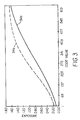
- FIG. 2 there is shown the characteristic relationship of output density to input exposure for a typical photosensitive medium 30.
- a density response curve 50 for silver-halide-based photosensitive medium 30 is typically plotted with exposure on a logarithmic scale to show the familiar D-logE relationship.
- This sensitometric relationship is similar for each red, green, and blue (RGB) component color, with differences between response for the different colors most accentuated at peak density (Dmax) and at minimum density (Dmin).
- RGB red, green, and blue
- CR maximum exposure / minimum exposure
- the exposure energy modulated by spatial light modulator 20 must be able to provide the contrast ratio needed for each color.
- the relative exposure energy level provided from spatial light modulator 20 is derived from a measurement sensed by an intensity sensor 40.
- Intensity sensor 40 can be any of a number of different types of photosensing devices.
- intensity sensor 40 is configured as a sensing circuit that provides an output voltage as a "raw energy" measurement that is proportional to the irradiance of incident exposure energy. Over the useful range of exposure energy levels of a preferred embodiment, for example, a typical voltage output from intensity sensor 40 may range between approximately 0.072 to 1.693 Vdc.
- the calibration method of the present invention generates a LUT that is stored in E-O calibration LUT memory 32, one for each type of photosensitive media 30.
- the LUT provides an m:n mapping that correlates m input data values to a larger number of n device code values, where each of the n device code values, in turn, corresponds to each of n different possible exposure energy values that can be obtained from spatial light modulator 20.
- the LUT from E-O calibration LUT memory 32 also stores a bias voltage setting for spatial light modulator 20. This bias setting enables spatial light modulator 20 to obtain the desired level of contrast ratio for a specific type of photosensitive medium 30.
- FIG 4 there is shown the overall sequence of steps used for creating a LUT that maps input code values to their corresponding device code values. Dotted lines trace the actions of individual steps and show the relation of each step towards achieving the desired mapping. It is instructive to note that the procedure of Figure 4 is executed for each type of photosensitive medium 30 to be used by printing system 10, and for each color component used.
- a bias setting is obtained for spatial light modulator 20.
- This bias setting intended to be available in memory such as in m:n mapping LUT 18, determines contrast response characteristics of spatial light modulator 20.
- an E-O device profiling step 80 raw energy measurements are obtained from intensity sensor 40 ( Figure 1) for each of the n device code values obtainable from spatial light modulator 20. In a preferred embodiment, for example, 640 different levels are available.
- an optional normalization step 82 normalizes the raw energy values obtained in the preceding step to simplify calculation.
- a discrete density-to-normalized E-O levels mapping step 84 begins by correlating the peak raw energy value obtained in E-O device profiling step 80 with the maximum density desired from the specific photosensitive medium 30. With this maximum mapping established, each lesser raw energy value is correlated with a corresponding discrete density value, using the known response profile for the specific photosensitive medium 30 at the specified color.
- sensitometric data for photosensitive medium 30 provided by the manufacturer such as the curve in Figure 2, for example, are used to derive corresponding discrete density values that can be achieved by each normalized raw energy level achieved from spatial light modulator 20.
- each of n device code values is then correlated to a corresponding discrete density.
- a discrete-to-target densities mapping step 86 then correlates each of the m target densities needed for calibration of the printer to the specific photosensitive medium 30 to one of the n discrete densities calculated for the device code values.
- discrete-to-target densities mapping step 86 it can be seen that some of the n discrete density values cannot be used.
- a number of algorithms can be used for mapping each of m target densities to one of the n discrete densities. The preferred embodiment uses a nearest-neighbor algorithm, however, other methods could be used within the scope of the present invention.
- An input code value-to-device code value step 88 then follows, simply correlating each of the m input code values to one of the n device code values based on the correlation done in preceding steps.
- the procedure of the present invention can be conceptualized as building a table where successive columns are added to each step, so that the result necessarily correlates the right-most column in the table (input code values) with the left-most column (device code values) to provide the mapping needed in an LUT.
- the calibration method of the present invention must be performed separately for each type of photosensitive medium 30 to be used with printing system 10.
- the proper LUT data can be transferred from E-O calibration LUT storage memory 32 to an m:n mapping LUT 18 for use by print engine control processor 44.
- the proper bias voltage must be provided for using spatial light modulator 20 with the specific type of photosensitive medium 30.
- the method of the present invention provides a pre-calibration of printing system 10 that can be performed and stored in E-O calibration LUT storage memory 32 during manufacture. Then, once printing system 10 is installed in the field, separate tone scale calibration can be used to generate a LUT stored and provided by tone scale calibration LUT memory 28.
- bias voltage setting to spatial light modulator 20 may also vary depending on the type of photosensitive medium 30 and depending further on the needed contrast ratio for the type of printing application.
- E-O calibration LUT storage memory 32 would also store at least one bias setting for each type of photosensitive medium 30 used in printer system 10.
- Illumination control 24 could also be adjusted to modify the intensity of light source 36 based on the type of photosensitive medium 30.
- the method of the present invention is substantially automated and executed according to programmed instructions run by control logic processor 12.
- m:n mapping LUT 18 is then loaded with the resulting values, enabling printing system 10 to automatically adapt its operation to any type of photosensitive medium 30 for which printing system 10 is programmed.
- different parts of this process could be automatically or manually executed.
- the method of the present invention could be used to index any number of possible input states to any of a plurality of output exposure levels.
- the present invention could alternately be employed where there are more possible input states than output exposure levels (that is, where m>n ).
Landscapes
- Engineering & Computer Science (AREA)
- Multimedia (AREA)
- Signal Processing (AREA)
- Control Of Exposure In Printing And Copying (AREA)
- Laser Beam Printer (AREA)
- Projection-Type Copiers In General (AREA)
- Fax Reproducing Arrangements (AREA)
Abstract
Description
Claims (3)
- In a printing apparatus that employs an electro-optical exposure device for forming, on a photosensitive medium, pixels having an output density ranging from a minimum density to a maximum density, using an exposure energy that varies according to an input data value based on a predetermined exposure-to-density correlation, a method of mapping a set of m said input data values to a larger set of n discrete exposure energy levels obtainable from said electro-optical exposure device, the method comprising:(a) obtaining said larger set of n discrete exposure energy levels by iteratively providing each of n device data values to said electro-optical exposure device and measuring, for said each of said n device data values, the corresponding said discrete exposure energy level;(b) identifying a maximum discrete exposure energy level from said larger set of n discrete exposure energy levels and normalizing each of said n discrete exposure energy levels with respect to said maximum discrete exposure energy level to create a set of n normalized exposure energy levels;(c) correlating each said n device data value to a corresponding said output density in monotonically increasing order to create said larger set of n discrete exposure energy levels by:(c1) correlating a maximum normalized exposure energy level to said maximum density;(c2) iteratively correlating each remaining said normalized exposure energy level to said corresponding said output density;(c3) conditioning each of said normalized exposure energy levels by density response characteristics of said photosensitive medium; and(d) correlating said set of m said input data values to said larger set of n discrete exposure energy levels based on said predetermined exposure-to-density correlation.
- The method of claim 1 wherein the step of obtaining said larger set of n discrete exposure energy levels further comprises the step of adjusting bias a voltage supplied to said electro-optical exposure device.
- The method of claim 1 further comprising the step of adjusting a light intensity value based on said density response characteristic of said photosensitive medium.
Applications Claiming Priority (2)
| Application Number | Priority Date | Filing Date | Title |
|---|---|---|---|
| US10/000,967 US20030086099A1 (en) | 2001-11-02 | 2001-11-02 | Calibration method for a printing apparatus using photosensitive media |
| US967 | 2001-11-02 |
Publications (2)
| Publication Number | Publication Date |
|---|---|
| EP1309177A2 true EP1309177A2 (en) | 2003-05-07 |
| EP1309177A3 EP1309177A3 (en) | 2005-12-21 |
Family
ID=21693753
Family Applications (1)
| Application Number | Title | Priority Date | Filing Date |
|---|---|---|---|
| EP02079360A Withdrawn EP1309177A3 (en) | 2001-11-02 | 2002-10-21 | Calibration method for printing apparatus using photosensitive media |
Country Status (3)
| Country | Link |
|---|---|
| US (1) | US20030086099A1 (en) |
| EP (1) | EP1309177A3 (en) |
| JP (1) | JP2003228143A (en) |
Family Cites Families (16)
| Publication number | Priority date | Publication date | Assignee | Title |
|---|---|---|---|---|
| US5760918A (en) * | 1989-09-27 | 1998-06-02 | Canon Kabushiki Kaisha | Image processing apparatus with conversion and reconversion of the number of bits per pixel |
| US5515180A (en) * | 1992-11-24 | 1996-05-07 | Sharp Kabushiki Kaisha | Image processing device |
| US5321525A (en) * | 1992-12-14 | 1994-06-14 | Xerox Corporation | Clustered halftoning with dot-to-dot error diffusion |
| US5608821A (en) * | 1994-08-03 | 1997-03-04 | Xerox Corporation | Method of high addressability error diffusion |
| US5870503A (en) * | 1994-10-20 | 1999-02-09 | Minolta Co., Ltd. | Image processing apparatus using error diffusion technique |
| JP3423491B2 (en) * | 1995-07-28 | 2003-07-07 | キヤノン株式会社 | Image processing method, printing method, image processing device, printing device, and display device |
| US5917963A (en) * | 1995-09-21 | 1999-06-29 | Canon Kabushiki Kaisha | Image processing apparatus and image processing method |
| US6118547A (en) * | 1996-07-17 | 2000-09-12 | Canon Kabushiki Kaisha | Image processing method and apparatus |
| US6233360B1 (en) * | 1996-09-24 | 2001-05-15 | Xerox Corporation | Method and system for hybrid error diffusion processing of image information using adaptive white and black reference values |
| US5815768A (en) * | 1997-02-28 | 1998-09-29 | Hewlett-Packard Company | Detection of toner depletion in an electrophotographic printing system |
| US6147771A (en) * | 1997-04-24 | 2000-11-14 | Konica Corporation | Method of image density adjustment and apparatus using the method |
| US6147698A (en) * | 1997-05-29 | 2000-11-14 | International Business Machines Corporation | Density control for a printer |
| US5913014A (en) * | 1997-07-21 | 1999-06-15 | Eastman Kodak Company | Transforms for digital images |
| US6473199B1 (en) * | 1998-12-18 | 2002-10-29 | Eastman Kodak Company | Correcting exposure and tone scale of digital images captured by an image capture device |
| US6483604B1 (en) * | 1999-02-26 | 2002-11-19 | Nex Press Solutions | Disk-based image storage system and method with prioritized loading and retrieval operations |
| US7012716B2 (en) * | 2000-05-31 | 2006-03-14 | Fuji Photo Film Co., Ltd. | Image recording apparatus, image recording method, and calibration system of image recording apparatuses |
-
2001
- 2001-11-02 US US10/000,967 patent/US20030086099A1/en not_active Abandoned
-
2002
- 2002-10-17 JP JP2002303087A patent/JP2003228143A/en not_active Withdrawn
- 2002-10-21 EP EP02079360A patent/EP1309177A3/en not_active Withdrawn
Also Published As
| Publication number | Publication date |
|---|---|
| US20030086099A1 (en) | 2003-05-08 |
| EP1309177A3 (en) | 2005-12-21 |
| JP2003228143A (en) | 2003-08-15 |
Similar Documents
| Publication | Publication Date | Title |
|---|---|---|
| US5859933A (en) | Image forming apparatus | |
| US5583644A (en) | System for correcting image density of an image forming system based on a detection result of a test image | |
| US5053866A (en) | Method and an associated apparatus for calibrating a color digital hardcopy device | |
| US5731884A (en) | Method of an apparatus for outputting halftone dot image | |
| EP1097431B1 (en) | Imaging system and method | |
| US20070097333A1 (en) | Determining an adjustment | |
| JP2581509B2 (en) | Thermal printer system and method used therefor | |
| EP1014687A2 (en) | Correcting exposure and tone scale of digital images captured by an image capture device | |
| EP1033030B1 (en) | Method and device for calibrating an imaging apparatus | |
| US5414531A (en) | Image forming control based on a stored operation condition | |
| JP4629226B2 (en) | Method and apparatus for calibrating an imaging device having a plurality of imaging output devices | |
| EP0515162A2 (en) | Image processing method and apparatus | |
| US20020071132A1 (en) | Optical printing apparatus | |
| CN1332553C (en) | Method for calibration independent defect correction in an imaging system | |
| US8130411B2 (en) | Image forming apparatus and method with color difference and gray level compensation and use of adjusted gray level conversion table | |
| EP1607908B1 (en) | System and method for automated correction of digital images | |
| US20030086099A1 (en) | Calibration method for a printing apparatus using photosensitive media | |
| JP2003051004A (en) | System and method for selecting image processing path by utilizing estimated appearance of noise | |
| US7574335B1 (en) | Modelling piece-wise continuous transfer functions for digital image processing | |
| US6373993B1 (en) | Image processing method and image processing apparatus | |
| US8274526B2 (en) | Method, apparatus and system for visual gamma correction of displays | |
| US20070097440A1 (en) | Partial dot error diffusion halftone calibration | |
| JPH09107476A (en) | Image forming device | |
| JPH08289150A (en) | Image recording apparatus and method | |
| JPH07248659A (en) | Highlight reproduction adjusting method for image forming device |
Legal Events
| Date | Code | Title | Description |
|---|---|---|---|
| PUAI | Public reference made under article 153(3) epc to a published international application that has entered the european phase |
Free format text: ORIGINAL CODE: 0009012 |
|
| AK | Designated contracting states |
Designated state(s): AT BE BG CH CY CZ DE DK EE ES FI FR GB GR IE IT LI LU MC NL PT SE SK TR |
|
| AX | Request for extension of the european patent |
Extension state: AL LT LV MK RO SI |
|
| PUAL | Search report despatched |
Free format text: ORIGINAL CODE: 0009013 |
|
| AK | Designated contracting states |
Kind code of ref document: A3 Designated state(s): AT BE BG CH CY CZ DE DK EE ES FI FR GB GR IE IT LI LU MC NL PT SE SK TR |
|
| AX | Request for extension of the european patent |
Extension state: AL LT LV MK RO SI |
|
| RIC1 | Information provided on ipc code assigned before grant |
Ipc: 7H 04N 1/40 A |
|
| AKX | Designation fees paid | ||
| REG | Reference to a national code |
Ref country code: DE Ref legal event code: 8566 |
|
| STAA | Information on the status of an ep patent application or granted ep patent |
Free format text: STATUS: THE APPLICATION IS DEEMED TO BE WITHDRAWN |
|
| 18D | Application deemed to be withdrawn |
Effective date: 20060622 |