EP1309104A1 - Calibration device, adaptive array device, calibration method, program recording medium and program - Google Patents
Calibration device, adaptive array device, calibration method, program recording medium and program Download PDFInfo
- Publication number
- EP1309104A1 EP1309104A1 EP01947998A EP01947998A EP1309104A1 EP 1309104 A1 EP1309104 A1 EP 1309104A1 EP 01947998 A EP01947998 A EP 01947998A EP 01947998 A EP01947998 A EP 01947998A EP 1309104 A1 EP1309104 A1 EP 1309104A1
- Authority
- EP
- European Patent Office
- Prior art keywords
- radio unit
- radio
- unit
- antenna
- transmission
- Prior art date
- Legal status (The legal status is an assumption and is not a legal conclusion. Google has not performed a legal analysis and makes no representation as to the accuracy of the status listed.)
- Granted
Links
Images





Classifications
-
- H—ELECTRICITY
- H01—ELECTRIC ELEMENTS
- H01Q—ANTENNAS, i.e. RADIO AERIALS
- H01Q3/00—Arrangements for changing or varying the orientation or the shape of the directional pattern of the waves radiated from an antenna or antenna system
- H01Q3/26—Arrangements for changing or varying the orientation or the shape of the directional pattern of the waves radiated from an antenna or antenna system varying the relative phase or relative amplitude of energisation between two or more active radiating elements; varying the distribution of energy across a radiating aperture
-
- H—ELECTRICITY
- H04—ELECTRIC COMMUNICATION TECHNIQUE
- H04B—TRANSMISSION
- H04B7/00—Radio transmission systems, i.e. using radiation field
- H04B7/02—Diversity systems; Multi-antenna system, i.e. transmission or reception using multiple antennas
- H04B7/04—Diversity systems; Multi-antenna system, i.e. transmission or reception using multiple antennas using two or more spaced independent antennas
- H04B7/08—Diversity systems; Multi-antenna system, i.e. transmission or reception using multiple antennas using two or more spaced independent antennas at the receiving station
- H04B7/0837—Diversity systems; Multi-antenna system, i.e. transmission or reception using multiple antennas using two or more spaced independent antennas at the receiving station using pre-detection combining
- H04B7/0842—Weighted combining
-
- H—ELECTRICITY
- H04—ELECTRIC COMMUNICATION TECHNIQUE
- H04B—TRANSMISSION
- H04B17/00—Monitoring; Testing
- H04B17/20—Monitoring; Testing of receivers
- H04B17/21—Monitoring; Testing of receivers for calibration; for correcting measurements
- H04B17/22—Monitoring; Testing of receivers for calibration; for correcting measurements for calibration of the receiver components
- H04B17/221—Monitoring; Testing of receivers for calibration; for correcting measurements for calibration of the receiver components of receiver antennas, e.g. as to amplitude or phase
-
- H—ELECTRICITY
- H04—ELECTRIC COMMUNICATION TECHNIQUE
- H04B—TRANSMISSION
- H04B7/00—Radio transmission systems, i.e. using radiation field
- H04B7/02—Diversity systems; Multi-antenna system, i.e. transmission or reception using multiple antennas
- H04B7/04—Diversity systems; Multi-antenna system, i.e. transmission or reception using multiple antennas using two or more spaced independent antennas
- H04B7/08—Diversity systems; Multi-antenna system, i.e. transmission or reception using multiple antennas using two or more spaced independent antennas at the receiving station
- H04B7/0837—Diversity systems; Multi-antenna system, i.e. transmission or reception using multiple antennas using two or more spaced independent antennas at the receiving station using pre-detection combining
- H04B7/084—Equal gain combining, only phase adjustments
-
- H—ELECTRICITY
- H04—ELECTRIC COMMUNICATION TECHNIQUE
- H04B—TRANSMISSION
- H04B17/00—Monitoring; Testing
- H04B17/10—Monitoring; Testing of transmitters
Definitions
- the present invention relates to a calibration apparatus, an adaptive array apparatus, a calibration method, a program recording medium for recording a computer-readable program, and a program, all of which are for measuring the differences of the transfer characteristics between a transmission unit and a reception unit of a plurality of radio systems within an adaptive array apparatus designed for radio communication.
- the spatial multiplexing method is a communication method that involves the usage of an adaptive array apparatus that forms a different directivity pattern (called an adaptive array pattern) for each of a plurality of mobile stations.
- an adaptive array pattern a different directivity pattern
- the adaptive array apparatus is able to perform communication functions by multiplexing the transmission and reception signals of the plurality of mobile stations simultaneously on the same frequency.
- An adaptive array apparatus includes a plurality of radio units made up of an antenna, a transmission unit, and a reception unit. And this apparatus forms directivity patterns (called array antenna patterns) for the entire antenna by adjusting the amplitudes and phases of the transmission signals and reception signals inputted to and outputted from each radio unit. More specifically, the array antenna patterns are formed by weighting the amplitudes and phases of the transmission signals and reception signals inputted to and outputted from each radio unit using a weight coefficient (also called a weight vector). The calculation of weight vectors is performed by a DSP (Digital Signal Processor) within the adaptive array apparatus.
- DSP Digital Signal Processor
- the mobile phone unit When an adaptive array is used in a mobile phone system, the mobile phone unit has physical limitations such as size and possible number of antennas, making it impossible for the mobile phone to perform the function of controlling the directivity pattern. Therefore, it is the radio base station that forms the directivity patterns both at times of reception and times of transmission. In that case, the array antenna pattern formed by the radio base station at the time of transmission is same as the one that has been optimally formed at the time of reception.
- This array antenna includes, as additional equipment, a calibration-specific desired signal generation means, a calibration-specific interference signal generation means, an electrical power control means for controlling the electrical power of the calibration-specific interference signal generation means, a combining means for combining the calibration-specific desired signal with the calibration-specific interference signal whose electrical power is controlled, and a distribution means for distributing the combined signal to the various antennas, so as to compensate for the transfer characteristics within a reception system.
- an object of the present invention is to provide a calibration apparatus, an adaptive array apparatus, a calibration method, a program recording medium and a program all of which are able to perform calibration processes without having additional equipment in the apparatus whose transfer characteristics are to be measured.
- the present invention provides a calibration apparatus that measures a correction value for a radio terminal which, for a purpose of performing radio communication by forming an array antenna pattern, includes at least a first radio unit and a second radio unit, each made up of a transmission unit, a reception unit, and an antenna, the calibration apparatus comprising: a first antenna; a second antenna; a control means for controlling the first radio unit and the second radio unit to perform transmission of signals with an array antenna pattern being formed, using a weight vector by which a directivity is oriented toward the first antenna and a null is directed toward the second antenna; and a measuring means for measuring transfer characteristics that are relative between the first radio unit and the second radio unit on the basis of a signal level of the signals received by either the first antenna or the second antenna.
- the calibration apparatus may have an arrangement wherein the control means controls the second radio unit to fluctuate, during the transmission by the first radio unit and the second radio unit, a phase and an amplitude of the signal transmitted, and the measuring means measures a phase fluctuation amount and an amplitude fluctuation amount as the transfer characteristics on the basis of the phase and the amplitude at such a time when the signal level of the signals received by the second antenna is minimum during the fluctuation.
- the phase fluctuation amount and the amplitude fluctuation amount can be measured by fluctuating 'the phase and the amplitude of only the signals transmitted by the second radio unit during the transmission performed by the first radio unit and the second radio unit, and matching the null direction with the direction of the second antenna.
- the calibration apparatus may further comprise a transmission means for transmitting, on a same frequency, a desired signal from the first antenna, and an interference signal from the .second antenna, wherein the control means (i) controls the radio terminal to calculate a weight vector by which the interference signal can be eliminated and the desired signal can be received by the first radio unit and the second radio unit, and then (ii) controls the first radio unit and the second radio unit to perform the transmission of the signals using the weight vector calculated.
- the present invention further provides an adaptive array apparatus including a plurality of radio units, each made up of a transmission unit, a reception unit, and an antenna, the adaptive array apparatus comprising: a selecting means for selecting a radio unit among the plurality of radio units; and a control means for controlling the selected radio unit and one of unselected radio units to perform transmission of signals between each other in order to measure transfer characteristics of the selected radio unit on the basis of the signals received.
- control means controls the selected radio unit and one of unselected radio units to perform transmission of signals between each other in order to measure transfer characteristics of the selected radio unit on the basis of the signals received; therefore, there is an effective result that the transfer characteristics can be measured without having an additional circuit. Furthermore, if only one radio unit is selected, the transfer characteristics of the particular radio unit can be measured, whereas, if two radio units are selected, the transfer characteristics that are relative between those two radio units (that is to say, the relative transfer characteristics) can be measured.
- the adaptive array apparatus may have an arrangement wherein the selecting means selects another radio unit after the measuring by the control means, and the control means calculates a correction value for each of the radio units on the basis of the transfer characteristics measured for each of the radio units.
- the adaptive array apparatus may have an arrangement wherein the selecting means selects two radio units, the two selected radio units perform the transmission of the signals with such an array antenna pattern being formed in which a null is directed toward the antenna of one of the unselected radio units, while the two selected radio units fluctuate one or both of a phase and an amplitude at one of the two selected radio units, and the control means determines that the transfer characteristics are one or both of the phase and the amplitude at such a time when a signal level of the signals received by the radio unit toward which a null is directed is minimum during the fluctuation.
- the adaptive array apparatus may have an arrangement wherein the two selected radio units form the array antenna pattern in which a null is directed toward the antenna of the unselected radio unit, by using a weight vector obtained at such a time when the two selected radio units perform an array-reception while eliminating the signal transmitted by one of the unselected radio units.
- the present invention further provides an adaptive array apparatus including a plurality of radio units each made up of a transmission unit, a reception unit, and an antenna, the adaptive array apparatus comprising: a selecting means for selecting four radio units among the plurality of radio units as a first radio unit, a second radio unit, a third radio unit, and a fourth radio unit; and a control means for (a) controlling the third and the fourth radio units to perform an array-transmission using a weight vector by which a direct ivity is oriented toward the antenna of the first radio unit and a null is directed toward the antenna of the second radio unit; and (b) measuring transfer characteristics that are relative between the third radio unit and the fourth radio unit on the basis of a signal level of the signals received by either the first radio unit or the second radio unit.
- the adaptive array apparatus may have an arrangement wherein the selecting means repeats selecting four radio units among the plurality of radio units, until each of all the plurality of radio units gets selected once as a fourth radio unit, and the control means calculates a correction value for each of the plurality of radio units using one of the plurality of radio units as a standard of relativity, on the basis of the transfer characteristics measured for each of the radio units.
- the adaptive array apparatus may have an arrangement wherein the control means further judges whether the transfer characteristics are correct by checking if either a sum or a product of the transfer characteristics of each of the radio units that are relative fits in a predetermined range.
- the present invention further provides a calibration method used in an adaptive array apparatus including a plurality of radio units, each made up of a transmission unit, a reception unit, and an antenna, the calibration method comprising: a selecting step of selecting a radio unit among the plurality of radio units; and a measuring step of controlling the selected radio unit and one of unselected radio units to perform transmission of signals between each other in order to measure transfer characteristics of the selected radio unit on the basis of the signals received.
- the present invention further provides a program recording medium storing a computer-readable program to be executed by a computer in an adaptive array apparatus including a plurality of radio units, each made up of a transmission unit, a reception unit, and an antenna, the program instructing the computer to execute: a selecting step of selecting at least one radio unit among the plurality of radio units; and a measuring step of controlling the selected radio unit and one of unselected radio units to perform transmission of signals between each other in order to measure transfer characteristics of the selected radio unit on the basis of the signals received.
- the computer in the adaptive array apparatus that reads the program is able to measure the transfer characteristics of the radio units without having additional equipment.
- radio base station The preferred embodiment of the radio base station, mobile phone, and measurement apparatus of the present invention will be explained in the following order.
- the following is a general overview of an adaptive array apparatus of the preferred embodiment when it performs the function of a radio base station in a mobile communications network.
- FIG. 1 shows the general structure of the primary units of an adaptive array apparatus of an embodiment of the present invention.
- the adaptive array apparatus includes radio units 1 through 4 and DSP (Digital Signal Processors) 50.
- DSP Digital Signal Processors
- 4 DSP 50 units are shown in the drawing, but, in actuality, only 1 is required.
- This adaptive array apparatus independently measures the correction values and, under normal communication conditions, it uses this measured correction value to perform its communication functions. In other words, this adaptive array apparatus also serves the function of a measurement apparatus.
- Radio unit 1 is composed of an antenna 10, a transmission unit 111 (TX1 in the drawing), a reception unit 112 (RX1), and an antenna switch 113 (SW1). Radio units 2 through 4 are constructed in the same fashion.
- ⁇ RX1 and ARX1 respectively represent the amount of phase fluctuation and,the amount of amplitude fluctuation produced when a signal passes through the antenna 10, the antenna switch 113, and the reception unit 112.
- ⁇ TX1 and ATX1 respectively represent the amount of phase fluctuation and the amount of amplitude fluctuation produced when a signal passes through the transmission unit 111, the antenna switch 113, and the antenna 10.
- ⁇ RX2 through ⁇ RX4 and ARX2 through ARX4 similarly represent the amount of phase and amplitude fluctuation occurring in their respective radio units.
- ⁇ 12 and Amp12 respectively represent the phase fluctuation amount and amplitude fluctuation amount of radio unit 2 relative to radio unit 1, which is used as the standard.
- ⁇ 23, ⁇ 34, and ⁇ 41, as well as Amp23, Amp34, and Amp41 similarly represent the relative amounts of phase and amplitude fluctuation occurring in their respective radio units relative to radio unit 1. These are defined by the following formulas.
- This adaptive array apparatus performs array-transmissions and array-receptions of known signals within radio units 1 through 4. Then, while changing the phase amounts and amplitude amounts, it seeks an adjustment value for the purpose of creating an array antenna pattern that is the same at the time of transmission and the time of reception. Accordingly, the adaptive array apparatus finds the relative phase fluctuation amounts and relative amplitude fluctuation amounts indicated by these formulas (1) through (8), and determines correction values for the purpose of compensating for the phase and amplitude fluctuation amounts. These correction values are defined by the following formulas (9) through (17).
- the above correction values are correction values relative to radio unit 1, which serves as the standard.
- the reason that it is acceptable to use these relative correction values is as follows: If the difference of the phase fluctuation amounts and the ratio of the amplitude fluctuation amounts of the radio units are equal at the time of reception and transmission, then, when the weight vector calculated at the time of reception is used, the same array antenna pattern as the array antenna pattern that was present at the time of reception will result.
- radio unit 1 was used as the standard, however it is acceptable to use any of the radio units as the standard.
- radio unit 3 were to serve as the standard, the following equations would define the phase correction values ((9') through (12')) and the amplitude correction values ((13') through (16')).
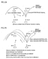
- FIGs. 2A and 2B are explanatory drawings that show the general operations of an adaptive array apparatus when ⁇ 34 and Amp34, expressed by equations (3) and (7), are measured.
- FIG. 2A shows the manner in which radio unit 1 independently transmits a desired signal and radio unit 2 independently transmits an interference signal wave, both radio units transmitting on the same frequency (in the drawing).
- the desired signal and the interference signal denote differing known series of data.
- radio units 3 and 4 serve as a 2-antenna adaptive array apparatus, receiving the desired signal by forming an array antenna pattern that corresponds to radio unit 1 (in the drawing) . That is to say, DSP 50 calculates a weight vector for the purpose of separating out the desired signal from a received signal on which both the desired signal and the interference signal are multiplexed.
- FIG. 2B shows the manner in which the radio units switch between transmission and reception.
- radio units 3 and 4 serving as a 2-antenna adaptive array apparatus, perform an array reception and use the weight vector calculated at the time of that array reception to perform an array transmission of the desired signal (in the drawing).
- the array antenna pattern produced at the time of this array transmission will be the same as that produced at the time of array reception as long as the amount of phase fluctuation and amplitude fluctuation within the transmission units and reception units within radio units 3 and 4 are the same.
- the directivity is oriented toward radio unit 2, and a null is directed toward radio unit 3. (When "a null is directed" to a point or a direction, it means that it is impossible or difficult for the radio waves to reach at such a point or a direction.)
- DSP 50 adds phase compensation amounts ⁇ to the transmission signal from radio unit 4 while altering the compensation amounts by 360 degrees (for example, one degree at a time, from -180 to +180 degrees). While this occurs, radio unit 2 measures the signal reception level in accordance with these alterations ( in the drawing) .
- DSP 50 also gradually alters the transmission signal amplitude compensation amount Amp coef of radio unit 4 (for example, from 0.5 to 2, by varying 0.1 at a time). While this occurs, radio unit 2 measures the signal reception level in accordance with these alterations ( in the drawing).
- the amplitude compensation amount Amp coef at the time when the reception signal level is the smallest satisfies the equation Amp34 ((ATX3/ARX3)/(ATX4/ARX4)). Accordingly, Amp34 is set as the amplitude compensation amount Amp coef at this time ( ).
- the adaptive array apparatus measures a relative phase fluctuation amount ⁇ 34 and a relative amplitude fluctuation amount Amp34. And in the same fashion, it measures a) ⁇ 41 and Amp41, b) ⁇ 12 and Amp12 and c) ⁇ ⁇ 23 and Amp23.
- DSP 50 determines whether the measured relative phase and amplitude fluctuation amounts are appropriate by using formulas (17) and (18) below. (17)
- ⁇ thre is, for example, the threshold value of 1 degree.
- the left section of this equation (17) involves the addition of the right sections of equations (1) through (4) listed earlier. Ideally, these amounts should add up to 0 (degrees), but in reality, measurement errors and mis-measurements due to waves of an external source are produced. Therefore, it is desirable that judgments be made based on the relationship to ⁇ thre. (18) A thre min ⁇ Amp12 * Amp23 * Amp34 * Amp41 ⁇ A thre max
- a thre min might be a threshold minimum value of 0.95 and A thre max a threshold maximum of 1.05.
- the middle section of this equation (18) involves the multiplication of the right sections of equations (5) through (8) listed earlier. Ideally, these amounts should add up to 1, but for the same reasons mentioned above, it is desirable that judgments be made based on the relationship to A thre min and A thre max.
- the adaptive array apparatus uses them to calculate the correction values indicated in equations (9) through (16) (or equations (9') through (16')). Then, at the time of transmission, DSP 50 uses these values to correct the transmission signal.
- the adaptive array apparatus performs an array reception into radio unit 3 and radio unit 4. And when it performs an array transmission by using the weight vector calculated at the time of the array reception, the phase fluctuation amount produced by radio unit 3 at the time of transmission relative to the time of reception is ( ⁇ TX3 - ⁇ RX3) and the phase fluctuation amount produced by radio unit 4 at the time of transmission relative to the time of reception is ( ⁇ TX4 - ⁇ RX4).
- the amplitude fluctuation amount produced by radio unit 3 at the time of transmission relative to the time of reception is (ATX3/ARX3) and the amplitude fluctuation amount produced by radio unit 4 at the time of transmission relative to the time of reception is (ATX4/ARX4).
- Fluctuation of the phase ⁇ of the transmission signal of radio unit 4 is done in small increments, and when the reception level at radio unit 2 is at a minimum, this means that the phase fluctuation amounts at radio units 3 and 4 have been compensated for.
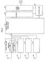
- FIG. 3 is a block diagram that shows the overall structure of a radio base station. As indicated in the diagram, it includes: a base band unit 70; a modem unit 60; a digital signal processor 50; front end units 11, 21, 31, and 41; antenna 10, 20, 30, and 40; and control unit 80.
- This radio base station is an adaptive array apparatus that creates wireless connections with mobile stations by using a plurality of antennas and forming array antenna patterns by weighting the transmission and reception signals of each antenna. It is constructed for the purpose of connecting PHS phones by using TDMA/TDD (Time Division Multiple Access/Time Division Duplex) methods set to meet PHS standard.
- TDMA/TDD Time Division Multiple Access/Time Division Duplex
- Base band unit 70 functions between a plurality of circuit lines that are connected via a telephone switching network and the modem unit 60. For each of a plurality of signals (base band signals that carry audio or data information) that require spatial multiplexing, the base band unit 70 performs a TDMA/TDD process for multiplexing and dividing the signals so that they fit into TDMA/TDD frames.
- a TDMA/TDD frame is made up of a 5mS period divided into 8 equal time slots, 4 transmission time slots and 4 reception time slots.
- the base band unit 70 multiplexes quadruply the signals from the circuit lines to the modem unit 60 for each TDMA/TDD frame. And further, for the purpose of spatial multiplexing, up to 4 signals can be sent to the modem unit 60 for every 1 transmission time slot. Additionally, the base band unit 70 inputs from the modem unit 60 to the circuit lines up to 4 signals for every 1 reception time slot, resulting in time division multiplexing that allows for an output to a plurality of circuit lines.
- the modem unit 60 modulates the signals inputted from the base band unit 70, and it demodulates the signals inputted from DSP 50.
- the method used for this modulation and demodulation is ⁇ /4 shift QPSK (Quadrature Phase Shift Keying) .
- DSP 50 is a digital signal processor that runs programs for performing weight vector calculations and the like. In particular, during the calibration process, this unit calculates the correction value to be used to compensate for the change in transfer characteristics between the time of reception and the time of transmission at radio units 1 through 4.
- front end units 11, 21, 31, and 41 convert into RF signals the signals that were weighted by DSP 50 and transmit the converted signals from antennas 10 through 40.
- the front end units convert the signals from antennas 10 through 40 into base band signals and output the converted signals to DSP 50.
- the assembly of antenna 10 and front end unit 11 shall be referred to as radio unit 1.
- the remaining antenna and front end unit shall be referred to as radio units 2, 3, and 4.
- radio units 1 through 4 independently transmit and receive each desired signal or interference signal generated by DSP 50 during its calibration process. Further, 2 of these radio units work in conjunction to perform array transmissions and array receptions of the desired signal or interference signal.
- Control unit 80 serves to control the overall radio base station, including to switch between transmission and reception of each radio unit.
- FIG. 4 is a block diagram that shows the detailed structure of DSP 50. It shows the functions that take place as a result of DSP 50 running its programs.
- DSP 50 is provided with user signal processing units 51a through 51d, adders 551 through 554, switches 561 through 564 for switching between transmission and reception, correction value retaining unit 570, and correction units 571 through 574.
- User signal processing units 51a through 51d are provided to correspond to the maximum of 4 user signals that are spatially multiplexed in each time slot. Normally (at times other than times of calibration processing), each user signal processing unit serves to control the array reception and array transmission that involves the usage of all 4 radio units. That is, at times of reception, the user signal processing units calculate weight vectors from the various reception signals coming from radio units 1 through 4. And, using these weight vectors, they extract a user signal by combining the reception signals that are input by the radio units 1 through 4 via the switches 561 through 564. At times of transmission, the user signal processing units use the weight coefficient calculated during the immediately preceding reception time slot to generate a weighted user signal and output that signal to each of the radio units 1 through 4.
- each user signal processing unit a) controls array reception and array transmission so that it occurs through 2 antennas; b) controls the desired signal so that, rather than being transmitted and received as an array, it is an independently transmitted and received signal via 1 radio unit; and c) controls the interference signal so that, rather than being transmitted and received as an array, it is an independently transmitted and received signal via 1 radio unit.
- DSP 50 determines the relative phase fluctuation amounts ( ⁇ 34, ⁇ ⁇ 41, ⁇ 12, and ⁇ 23) and relative amplitude fluctuation amounts (Amp34, Amp41, Amp12, and Amp 23), and uses these amounts to calculate the correction values ( ⁇ correction 1 through ⁇ correction 4, and A correction 1 through A correction 4).
- the adder 551 combines the weighted components of each user transmission signal corresponding to radio unit 1. However, in cases such as that indicated in FIG. 2A where independent transmission takes place from radio unit 1 or that indicated in FIG. 2B where a 2-antenna array transmission is performed using radio unit 1, the transmission signals (desired signals, interference signals, etc.) from any of the user signal processing units are directly outputted without being added to any other signals. Adders 552 through 554 perform the same function, varying in the fact that they do so in relation to their respective radio units 2 through 4.
- Correction value retaining unit 570 retains the correction values ( ⁇ correction 1 through ⁇ correction 4, and A correction 1 through A correction 4) that are calculated during the calibration process.
- correction unit 571 uses the correction values ⁇ correction 1 and A correction 1 retained in the correction value retaining unit 570, corrects the transmission signals arising from adder 551 and outputs these signals to radio unit 1 via switch 561. And at times of calibration processing, the transmission signals arising from adder 551 are output directly to radio unit 1 via switch 561. However, if the relative phase and amplitude fluctuation amounts at radio unit 1 are being measured during a time of calibration processing, the phase compensation amount ⁇ and the amplitude compensation amount Amp are applied to the transmission signals while being altered gradually.
- Correction units 572 through 574 function in the same manner in relation to their respective radio units other than the fact the correction values retained by the correction value retaining unit 570 are different.
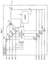
- FIG. 7 is a block diagram showing the detailed structure of the user signal processing unit 51a.
- User signal processing units 51b through 51d have the same structure, so here user signal processing unit 51a will serve as a representative example as it is explained.
- the user signal processing unit 51a is provided with a weight calculating unit 53, an adder 54, a memory 55, switches 56 and 57, multipliers 521 through 524, and multipliers 581 through 584.
- the weight calculating unit 53 calculates a weight vector in order to minimize an error between a reference signal generated by the memory 55 and the sum of the weighted reception signals S1R through S4R from each of the radio units 1 through 4, during each symbol period of a fixed bit pattern period within a reception time slot. And at times of calibration, the weight vector calculation for the purpose of an array reception using 2 antennas is performed in the same manner. The following is an explanation of weight vector calculation for a 4-antenna array reception. Note that the process is the same for 2-antenna array receptions; simply the number of elements involved is reduced.
- t represents the timing of a symbol unit
- d(t) represents the symbol data within the known reference signal (or training signal)
- W1(t-1) through W4 (t-1) represent either the weight coefficient of each antenna that was calculated for the immediately preceding symbol or the weight coefficient calculated at the immediately preceding reception time slot
- X1(t) through X4 (t) represent the reception signals for antennas 10 through 40.
- the weight vectors are adjusted in the above manner for every symbol. Therefore, even if the error e(t) is large at the beginning of a reference signal period within the reception time slot, it will be reduced to a minimum (or reduced to 0) by the end of that reference signal period.
- the weight calculating unit 53 outputs the calculated weight coefficients to the multipliers 521 through 524. Additionally, during a given transmission time slot, the weight calculating unit 53 outputs to the multipliers 581 through 584 the weight coefficient calculated during the reception time slot that corresponds to the immediately preceding transmission time slot.
- the memory 55 stores a) waveform data of series of symbols that represent the reference signals used at times other than calibration processing (times of normal communication with mobile stations), b) waveform data of series of symbols that represent the desired signals used for calibration processing, and c) waveform data of series of symbols that represent interference signals.
- the reference signal is retrieved by the weight calculating unit 53 in synchronization with the symbol timing during the reception period of known fixed bit patterns (fixed symbols) within a reception time slot. For example, in the case of PHS systems, the SS (start symbol), PR (preamble), and UW (unique word) are fixed symbols that appear in the front end of the reception time slot.
- the desired signal and the interference signal are known series of symbol data such as PN (Pseudo-random Noise) symbols, and it is desirable that they be arranged orthogonal to each other. If arranged orthogonal to each other, the weight vectors can be more rapidly converged and more accurately calculated. Note that when the same PN symbols or fixed symbols are used, it is best to stagger the timing (for instance, by 0.5 symbol periods).
- the desired signal and the interference signal are retrieved by the weight calculating unit 53 as reference signals (training signals) .
- the desired signal and the interference signal are retrieved from the memory 55 as transmission signals, and suppliedto multipliers 581 through 584 via switch 57.
- only one output will be transmitted from a specific multiplier among the multipliers 583 through 584 which corresponds to a radio unit that produces an independent transmission.
- each user signal processing unit has the same structure, for ease of explanation, each processing unit will be assumed to undergo a particular fixed process during the calibration process.
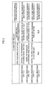
- FIG. 5 simply lays out the contents of the processes undergone within each user signal processing unit.
- Ant1 through Ant4 within the drawing represent theoretical radio units that are placed in direct 1-to-1 relationships with the physically existing radio units 1 through 4. These 1-to-1 relationships are shown in FIG. 6. There are numerous possible relationships, and the present embodiment has at least the 4 indicated by Cases 1 through 4 of FIG. 6.
- control unit 80 causes all radio units to use the same frequency, with Ant1 and Ant2 performing transmission, and Ant3 and Ant4 performing reception.
- user signal processing unit 51a has Ant1 transmit an independent desired signal. That is, it generates a desired signal and supplies it to Ant1.
- User signal processing unit 51b has Ant2 transmit an independent interference signal. That is, it generates an interference signal and supplies it to Ant2.
- User signal processing unit 51c controls a 2-antenna array reception of reception signals from both Ant3 and Ant4. That is, it calculates weight vectors.
- control unit 80 causes all radio units to use the same frequency, with Ant1 and Ant2 performing reception, and Ant3 and Ant4 performing transmission.
- user signal processing unit 51c controls a 2-antenna array transmission of a desired signal using Ant3 and Ant4. That is, it uses the weight vector calculated above to weight a desired signal and supply that signal to Ant3 and Ant4.
- user signal processing unit 51c alters the phase compensation amount ⁇ , as shown in of FIG. 2B, and, after that, it alters the amplitude compensation amount Amp coef, as shown in of FIG. 2B.
- User signal processing unit 51a receives an independent reception signal from Ant1.
- User signal processing unit 51b receives an independent reception signal and an indication of the level of that reception signal from Ant2 each time the phase compensation amount ⁇ and the amplitude compensation amount Amp coef are altered.
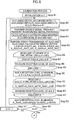
- FIGs. 8 and 9 are flowcharts showing more detailed contents of the calibration process.
- n represents a variable for the purpose of counting from 1 to 4.
- DSP 50 selects which physically existing radio units 1 through 4 will serve as which theoretical radio units Ant1 through Ant4 (Step 82).
- Ant1 is selected to independently transmit and receive the desired signal
- Ant2 to independently transmit and receive the interference signal
- Ant3 and Ant4 are selected for the purpose of array reception and array transmission.
- DSP 50 then has Ant 1 transmit the desired signal and has Ant 2 transmit the interference signal (Step 83). Simultaneously, it has Ant3 and Ant4 function as an adaptive array apparatus to form an array antenna pattern for the desired signals sent from Ant1. That is to say, DSP 50 calculates a weight vector for the purpose of separating out the desired signal from the reception waves that include both desired signals and interference signals in a multiplexed form (Step 84). At this time, user signal processing unit 51a supplies the desired signal to Ant1 and user signal processing unit 51b supplies the interference signal to Ant2. Additionally, user signal processing unit 51c calculates the weight vectors of the reception signals from Ant3 and Ant4.
- DSP 50 uses Ant3 and Ant4 as a 2-antenna adaptive array apparatus to perform an array transmission of the desired signal by using the calculated weight vector, and b) switches Ant2 to independent reception (Step 85).
- user signal processing unit 51c weight the signal using the weight vectors.
- DSP 50 alters the assembly of theoretical radio units Ant1 through Ant4, which were chosen from the physically existing radio units 1 through 4. While performing these alterations, DSP 50 measures ⁇ 41 and Amp41 during the second loop, ⁇ ⁇ 12 and Amp12 during the third loop, and ⁇ 23 and Amp23 during the fourth loop.
- DSP 50 judges the measured relative phase fluctuation amounts ( ⁇ 34, ⁇ 41, ⁇ 12, ⁇ ⁇ 23) and amplitude fluctuation amounts (Amp34, Amp41, Amp12, and Amp23) to determine whether they are valid (Steps 98 and 99). This determination is based on whether or not both of the earlier-explained equations (17) and (18) are satisfied. If either of these is not satisfied, then the calibration process is terminated and recommenced from the beginning.
- DSP 50 calculates phase correction values ⁇ correction 1 through ⁇ correction 4 and amplitude correction values A correction 1 through A correction 4 in accordance with the earlier-explained equations (9') through (16') (Steps 100 and 101). Then the calculated correction values are written to correction value retaining unit 570 and are used for correcting the transmission signal of the various radio units at times of normal array transmission when calibration is not taking place.
- the adaptive array apparatus of the present embodiment allows for array transmission to take place between 2 radio units selected from a plurality of radio units and other radio units. And in accordance with the resulting reception signals, the transfer characteristics of the selected radio units can be measured, making it possible to calculate the relative transfer characteristics of each radio unit without any additional apparatuses.
- the adaptive array apparatus shown in FIG. 1 is a radio base station. By using the 4 antennas of this station as those for the purpose of transmission and those for the purpose of reception, it was possible to measure relative correction values (in other words, to calibrate the values) within the apparatus itself using one radio unit as a standard relative. However, in the case of an adaptive array apparatus that uses 2 antennas for the formation of array antenna patterns, such as a mobile phone, it is impossible to measure correction values within the apparatus itself. Such an apparatus as a mobile phone requires that the correction values be measured with the cooperation of another measurement apparatus.
- the mobile phone it will be arranged so that the calculated correction values will be stored, and only the transmission signals from antennas other than the one serving as the standard will be corrected with the correction values.
- FIG. 10 is a block diagram showing the arrangement of primary units in a mobile phone of the embodiment of the present invention.
- mobile phone 200 is provided with: a) a radio unit (hereinafter referred to as radio unit A) made up of antenna 210, switch 213, transmission circuit 211, and reception circuit 212; b) a radio unit (hereinafter referred to as radio unit B) made up of antenna 220, switch 223, transmission circuit 221, and reception circuit 222; c) DSP 260 (indicated by the dashed line in the drawing); and d) external I/F 250.
- radio unit A a radio unit
- radio unit B a radio unit made up of antenna 220, switch 223, transmission circuit 221, and reception circuit 222
- DSP 260 indicated by the dashed line in the drawing
- external I/F 250 external I/F 250.
- This is an adaptive array apparatus that transmits by forming array antenna patterns with 2 antennas.
- Either of the two antennas 210 and 220 can be any of an assortment of antennas such as a rod antenna, a flat-surfaced pattern antenna, a helical antenna at the end of a rod, and a chip antenna (made up of chip components installed upon a base board) .
- antenna 210 is a rod antenna
- antenna 220 is a chip antenna.
- DSP 260 which is indicated by the dashed lines in the drawing, actually operates in accordance with a program. In this drawing, the operations are indicated by being divided into blocks that represent particular functions.
- the functions of DSP 260 correspond to multipliers 214, 224, 215, and 225, adder 230, demodulating circuit 231, re-modulating circuit 232, memory 233, switch 234, counter 235, weight calculating unit 236, memory 237, weight control unit 238, correction control unit 239, phase shifter 240, amplifier 241, and modulating circuit 242.
- Multipliers 214 and 224 respectively weight the reception signals inputted from reception circuits 212 and 222 by multiplying them by weight vectors W1 and W2 produced by weight calculating unit 236.
- Multipliers 215 and 225 respectively weight the transmission signals inputted by modulating circuit 242 by multiplying them by weight vectors W1 and W2 produced by weight control unit 238. Then they output these weighted transmission signals to transmission circuit 211 and phase shifter 240.
- Adder 230 adds together the reception signals that were weighted by multipliers 214 and 224.
- Demodulating circuit 231 demodulates the reception signals that result after addition is performed by adder 230.
- the demodulated reception signals are outputted as reception series of bit data.
- Re-modulating circuit 232 re-modulates reception series of bit data that are inputted by demodulating circuit 231, converting the reception series of bit data into symbol data (waveform data of symbols).
- the reference signal table stores symbol data (waveform data of symbols) that represents reference signals used at times other than the calibration process (times of normal reception from the radio base station), and it stores symbol data that represents desired signals that are used at times of calibration.
- the reference signals and desired signals are the same as those included in the explanation of the radio base station.
- counter 235 counts, in synchronization with the symbol timing, the number of symbols in a reception time slot from the front end to the tail end (in a PHS, this ranges from 0 to 120). The resulting count value is used for the purpose of distinguishing symbol periods with a fixed bit pattern from other periods.
- the symbol periods of the third symbol through the 16 th symbol correspond to the fixed bit pattern periods of SS, PR, and UW.
- switch 234 selects the symbol data (waveform data) that represents the reference signal retrieved from memory 233. For all other periods, switch 234 selects the symbol data from re-modulating circuit 232. And during the calibration process, it selects the symbol data that represents the desired signal retrieved from the memory 233.
- weight calculating unit 236 calculates a weight vector for every symbol in order to minimize the error between the sum of the weighted reception signals inputted from reception circuit 212 and reception circuit 222 and the symbol data inputted from switch 234 .
- weight calculating unit 236 calculates a weight vector for every symbol in order to minimize the error between the sum of the weighted reception signals inputted from reception circuit 212 and reception circuit 222 and the symbol data inputted from switch 234 .
- weight calculating unit 236 calculates a weight vector for every symbol in order to minimize the error between the sum of the weighted reception signals inputted from reception circuit 212 and reception circuit 222 and the symbol data inputted from switch 234 .
- the calculation of weight vectors in this case it is performed in the same manner as weight calculating unit 53.
- Memory 237 which includes RAM and ROM, stores the weight vector calculated by weight calculating unit 236 and relative correction value for radio unit B that uses radio unit A as the standard. During normal reception, it is acceptable that this weight vector be the weight vector calculated according to the symbol at the tail end of a reception time slot. It is used in the transmission time slot that immediately follows the reception time slot. During the calibration process, memory 237 stores the weight vector calculated upon the reception of the desired signal, and this weight vector is used for the immediately following desired signal transmission.
- the weight vectors for radio units A and B are referred to respectively as W1 and W2.
- correction values are expressed using the following formulas (20) and (21), and the values measured during the calibration process are written onto the ROM storage area within memory 237 before it is shipped from the manufacturers.
- ⁇ 12 (( ⁇ TX1 - ⁇ RX1) - ( ⁇ TX2 - ⁇ RX2))
- Amp12 ((ATX1/ARX1) / (ATX2/ARX2))
- FIG. 11 is an explanatory drawing of the correction values.
- ⁇ RX1 and ARX1 respectively represent the phase fluctuation amount and the amplitude fluctuation amount produced when a signal from antenna 210 passes through switch 213 and reception circuit 212.
- ⁇ TX1 and ATX1 respectively represent the phase fluctuation amount and the amplitude fluctuation amount produced when a signal passes from transmission circuit 211 and switch 213 to antenna 210.
- ⁇ RX2 through ⁇ RX4 and ARX2 through ARX4 similarly represent phase and amplitude fluctuation amounts within their respective radio units.
- ⁇ 12 and Amp12 in the above formulas (20) and (21) respectively represent the relative phase and amplitude fluctuation amounts of radio unit B, with radio unit A serving as the standard.
- weight control unit 238 retrieves weight vectors W1 and W2 from memory 237. Then it outputs these weight vectors to multipliers 215 and 216. The same occurs when a desired signal is transmitted during a calibration process.
- correction control unit 239 retrieves correction values ⁇ 12 and Amp12 from memory 237, then respectively outputting these values to phase shifter 240 and amplifier 241. Additionally, within the calibration process at the time of transmission of the desired signal, correction control unit 239 outputs ⁇ to the phase shifter 240 while altering it from -180 to +180 degrees one degree at a time, for instance. And it outputs Amp to the amplifier 241 while gradually altering it (for example, between 0.5 and 2, 0.05 units at a time).
- Phase shifter 240 corrects the phase of the transmission signal inputted from multiplier 225 according to the correction value ⁇ 12 inputted from correction control unit 239.
- Amplifier 241 corrects the amplitude of the transmission signal inputted from phase shifter 240 according to the correction value Amp12 inputted from correction'control unit 239. Then it outputs the corrected transmission signal to transmission circuit 221.
- modulating circuit 242 modulates the series of bit data to be transmitted, generating a transmission signal (symbol data).
- External I/F 250 is a connector connected to the DSP 260 input/output port and the DSP 260 memory (including memories 233 and 237) port. It is installed onto the baseboard of the mobile phone. During the calibration process, this external I/F 250 is connected to the external measurement apparatus and is used for the input/output of the various programs, data, commands, and replies to those commands.
- reception takes place by the formation of an array antenna pattern based on weight vectors calculated in a reception time slot.
- the weight vectors are stored in memory 237.
- transmission takes place by the formation of an array antenna pattern based on the stored weight vectors.
- correction control unit 239 uses correction values ⁇ 12 and Amp12 stored in memory 237 to correct the transmission signal of radio unit B.
- correction values ⁇ 12 and Amp12 stored in memory 237 it is possible to make corrections that ensure that there will be no deviation in the array antenna pattern at the time of reception and at the time of transmission.
- directivity of the signal at the time of reception can be made to match the directivity of the signal at the time of transmission by simply correcting the transmission signal of radio unit B. There is no need to correct the transmission signal of radio unit A, which serves as the standard.
- ⁇ 12 and Amp12 are the same physical amounts as the weight vectors it is acceptable that the structure of the invention be such that the correction weight vectors that represent ⁇ ⁇ 12 and Amp12 be stored in memory 237, and multipliers are provided in place of phase shifter 240 and amplifier 241. Additionally, one should note that the circuits of correction units 571 through 574 are equivalent to those of phase shifter 240 and amplifier 241, as well as those the multipliers.
- antenna 210 is a rod antenna and antenna 220 is a chip antenna
- the above-mentioned Amp12 value be a value compensated by an antenna gain compensation value A_cmp, as indicated below.
- Amp12 A_cmp* ((ATX1/ARX1)/(ATX2/ARX2))
- FIG. 12 is a block diagram showing the mobile phone and the structure of the measurement apparatus that measures the correction values (in other words, calibrates the values) of the mobile phone.
- the measurement apparatus is provided with a transmission and reception apparatus 301, a transmission apparatus 302, a timing adjuster 331, a control PC 330, a clock generation circuit 332, and an I/F unit 333.
- transmission and reception apparatus 301 is provided with an antenna 310, a transmission circuit 311, a signal selection unit 312, a reception circuit 313, a level measurement unit 314, and a switch 315. With this arrangement, it functions to receive a desired signal that is transmitted from the mobile phone 200 after an interference signal is transmitted.
- transmission circuit 311 transmits from antenna 310 an interference signal that is inputted from signal selection unit 312.
- Signal selection unit 312 stores series of symbol data of a plurality of interference signals. Then it selects one of the interference signals and outputs it to transmission circuit 311.
- This plurality of interference signals includes a) primary interference signals made up of PN codes, and b) secondary interference signals made up of known series of codes, including the fixed bit patterns (SS, PR, UW) that are the same as normal transmission time slots. The selection of interference signals is dependent on commands from control PC 330.
- reception circuit 313 receives from the mobile phone 200 a transmission signal that directs a null toward transmission and reception apparatus 301.
- Level measurement unit 314 measures the reception signal level of the reception signal of reception circuit 313. Then it notifies control PC 330 of the measured reception signal level.
- transmission apparatus 302 transmits the desired signal by being equipped with an antenna 320, a transmission circuit 321, and a signal selection unit 322.
- transmission circuit 321 transmits from antenna 320 a desired signal that is inputted from signal selection unit 322.
- Signal selection unit 322 stores series of symbol data of a plurality of desired signals. Then it selects one of the desired signals and outputs it to transmission circuit 321.
- This plurality of desired signals includes a) primary desired signals made up of PN codes that are orthogonal to the primary interference signal and b) secondary desired signals made up of known series of codes, including the fixed bit patterns (SS, PR, UW) that are the same as normal transmission time slots.
- the selection of interference signals is dependent on commands from control PC 330.
- timing adjuster 331 When signal selection units 312 and 322 respectively select a primary interference signal and a primary desired signal, timing adjuster 331 directly outputs to transmission and reception apparatus 301 the clock signal (symbol clock) inputted from signal selection unit 322.
- timing adjuster 331 When signal selection units 312 and 322 respectively select a secondary interference signal and a secondary desired signal, timing adjuster 331 outputs to transmission and reception apparatus 301 the clock signal inputted from signal selection unit 322 after, for example, delaying the signal by a 0.5 symbol time.
- the reason for this delay lie's in the fact that both the secondary interference signal and the secondary desired signal include the same fixed bit patterns (SS, PR, UW, etc.). That is, the delay makes it easier to separate out the desired signal occurring in the mobile phone 200. It is not necessary for the timing adjuster 331 to perform a delay when a primary interference signal and primary desired signal are selected, but, for ease of construction, it is acceptable for the timing adjuster 331 to be designed so that the delay takes place.
- control PC 330 controls transmission and reception apparatus 301, transmission apparatus 302, timing adjuster 331, and mobile phone 200 in order to measure the correction value of radio unit B that uses as a standard radio unit A of mobile phone 200.
- Clock generation circuit 332 outputs a clock signal, which indicates symbol timing, to transmission apparatus 302 and timing adjuster 331.
- I/F unit 333 is connected to external I/F 250 that is within mobile phone 200. It serves as an interface for the input/output of commands and data to and from mobile phone 200.
- FIG. 13 shows an example of the outer appearance of and the physical connections between the measurement apparatus and mobile phone 200.
- the mobile phone 200 is shown as merely a baseboard without its casing and I/F unit 333 is shown as a connector on the baseboard fitted together with external I/F 250.
- transmission and reception apparatus 301 and transmission apparatus 302 can be constructed from typical signal generators, or they can be constructed by modifying the radio base station or the mobile phone.
- external I/F 250 can be a plurality of pads provided on the baseboard.
- I/F unit 333 can be a probe connected to the plurality of pads.
- the measurement apparatus and mobile phone shown in FIG. 13 are placed in an electromagnetically shielded anechoic chamber or the like.
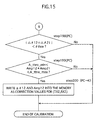
- FIGs. 14 and 15 are flowcharts that show the calibration process that takes place under the control of control PC 330. Although these drawings are basically the same in content as FIGs. 8 and 9, the actual unit performing each step varies.
- (PC ⁇ K) indicates the step which is triggered by commands or data that are sent from control PC 330 to mobile phone 200.
- (PC ⁇ T) indicates the step is triggered by commands or data that are sent from control PC 330 to transmission and reception apparatus 301 or transmission apparatus 302.
- PC indicates steps that occur within control PC 330.
- n is a variable for the purpose of counting from 1 to 2.
- control PC 330 determines that transmission apparatus 302, transmission and reception apparatus 301, radio unit A (TX1, RX1 in drawing), and radio unit B (TX2, RX2 in drawing) will respectively serve as radio units Ant 1 through Ant 4 (Step 182). These correspond to Ant1 through Ant4 in FIGs. 2A and 2B.
- Control PC 330 commands Ant1 (transmission apparatus 302) and Ant2 (transmission and reception apparatus 301) to transmit a primary desired signal and a primary interference signal. This causes the primary desired signal waves and primary interference signal waves from transmission apparatus 302 and transmission and reception apparatus 301, respectively, to be transmitted on the same frequency (Step 183). Further, control PC 330 uses Ant3 and Ant4 as a 2-antenna adaptive array apparatus to form array antenna pattern for the desired signals sent from Ant1. That is to say, control PC 330 commands the mobile phone 200 to calculate a weight vector for the purpose of separating out the desired signal from the reception waves that include both desired signals and interference signals in a multiplexed form. This causes the weight calculating unit 236 of mobile phone 200 to calculate a weight vector for the purpose of receiving the primary desired signal (Step 184).
- control PC 330 a commands transmission and reception apparatus 301 to measure the reception signal level at Ant2 for every Amp coef, b) obtains these measurement results, and c) stores this information in its internal memory (Steps 191 through 194.)
- the amplitude compensation amount Amp coef at this time is multiplied by the transmission signal from phase shifter 240 by means of correction control unit 239 and amplifier 241 shown in FIG. 10.
- control PC 330 switches Ant3 with Ant4. That is, it performs the same processes (Steps 183 through 195) with Ant3 functioning as radio unit B and Ant4 functioning as radio unit A (Steps 196 and 197).
- the phase shifter 240 and amplifier 241 within the mobile phone 200 do not alter the phase and amplitude.
- weight control unit 238 calculates a weight vector in which the above-mentioned ⁇ and Amp coef are added to the weight vector W2. Then multiplier 215 uses this calculated weight vector to perform a weighting function.
- control PC 330 determines whether the measured relative phase fluctuation amounts ( ⁇ 12 and ⁇ 21) and relative amplitude fluctuation amounts (Amp12 and Amp21) are appropriate (Steps 198 and 199). This determination is dependent on whether or not the equations (22) and (23) are satisfied. Other than the fact that only two correction values are used, these equations are the same as (17) and (18). (22)
- control PC 330 does not satisfy either of these equations, the calibration process should be terminated and recommenced from the beginning. In such an instance, it is preferable that changes be made to the conditions, for example, to the desired signal and the interference signal.
- control PC 330 commands mobile phone 200 to write the correction values ⁇ 12 and Amp 12 into memory 237 (Step 200). This results in memory 237 of mobile phone 200 storing the correction values ⁇ 12 and Amp12.
- the relative correction values of radio unit B, relative to radio unit A within mobile phone 200 are measured, and the correction values are established within mobile phone 200.
- the calibration apparatus, the adaptive array apparatus, the calibration method, the program recording medium therefor, and the program therefor, in the present invention make it possible to measure the relative phase fluctuation amounts and the relative amplitude fluctuation amounts at the antennas of the adaptive array as correction values, and are applicable for adaptive array apparatuses at radio base stations for mobile phones, and radio communication devices which perform array-transmissions and array-receptions.
Landscapes
- Engineering & Computer Science (AREA)
- Computer Networks & Wireless Communication (AREA)
- Signal Processing (AREA)
- Physics & Mathematics (AREA)
- Electromagnetism (AREA)
- Variable-Direction Aerials And Aerial Arrays (AREA)
- Radio Transmission System (AREA)
- Mobile Radio Communication Systems (AREA)
Abstract
Description
a control means for controlling the selected radio unit and one of unselected radio units to perform transmission of signals between each other in order to measure transfer characteristics of the selected radio unit on the basis of the signals received.
Claims (52)
- A calibration apparatus that measures a correction value for a radio terminal which, for a purpose of performing radio communication by forming an array antenna pattern, includes at least a first radio unit and a second radio unit, each made up of a transmission unit, a reception unit, and an antenna, the calibration apparatus comprising:a first antenna;a second antenna;a control means for controlling the first radio unit and the second radio unit to perform transmission of signals with an array antenna pattern being formed, using a weight vector by which a directivity is oriented toward the first antenna and a null is directed toward the second antenna; anda measuring means for measuring transfer characteristics that are relative between the first radio unit and the second radio unit on the basis of a signal level of the signals received by either the first antenna or the second antenna.
- The calibration apparatus of Claim 1, whereinthe control means controls the second radio unit to fluctuate, during the transmission by the first radio unit and the second radio unit, a phase and an amplitude of the signal transmitted, andthe measuring means measures a phase fluctuation amount and an amplitude fluctuation amount as the transfer characteristics on the basis of the phase and the amplitude at such a time when the signal level of the signals received by the second antenna is minimum during the fluctuation.
- The calibration apparatus of Claim 2, further comprisinga transmission means for transmitting, on a same frequency, a desired signal from the first antenna, and an interference signal from the second antenna, whereinthe control means (i) controls the radio terminal to calculate a weight vector by which the interference signal can be eliminated and the desired signal can be received by the first radio unit and the second radio unit, and then (ii) controls the first radio unit and the second radio unit to perform the transmission of the signals using the weight vector calculated.
- A calibration apparatus that measures a correction value for an adaptive array apparatus which includes at least a first radio unit and a second radio unit, each made up of an antenna, a transmission unit, and a reception unit, so that identical array antenna patterns are formed at times of transmission and reception, the calibration apparatus comprising:a control means for controlling the first radio unit and the second radio unit to perform transmission of signals with such an array antenna pattern being formed in which either a null or a directivity is oriented toward a specific direction ;a fluctuation means for controlling the second radio unit to fluctuate during the transmission either a phase or an amplitude of the signal transmitted by the second radio unit;a measuring means for measuring a signal level of the signals transmitted from the specific direction for each of values of the phase or the amplitude during the fluctuation; anda determining means for determining a correction value of the second radio unit relative to the first radio unit on the basis of either the value of the phase or the value of the amplitude at such a time when the signal level measured is either minimum or maximum.
- The calibration apparatus of Claim 4, further comprisinga transmission means for transmitting, on a same frequency, a desired signal and an interference signal from other antennas respectively, whereinthe control means (a) controls the adaptive array apparatus to calculate, for each of the signals received by the first radio unit and the second radio unit, a weight coefficient by which the interference signal can be eliminated and the desired signal can be received; and (b) controls the first radio unit and the second radio unit to perform the transmission of the signals with such an array antenna pattern being formed in which a null is directed toward the specific direction being a direction of the antenna that has transmitted the interference signal, by weighting the signals transmitted by the first radio unit and the second radio unit using the weight coefficients calculated, andthe measuring means measures the signal level using the antenna that has transmitted the interference signal.
- An adaptive array apparatus including a plurality of radio units, each made up of a transmission unit, a reception unit, and an antenna, the adaptive array apparatus comprising:a selecting means for selecting a radio unit among the plurality of radio units; anda control means for controlling the selected radio unit and one of unselected radio units to perform transmission of signals between each other in order to measure transfer characteristics of the selected radio unit on the basis of the signals received.
- The adaptive array apparatus of Claim 6, whereinthe selecting means selects another radio unit from the unselected radio units every time the transfer characteristics of the selected radio unit finish being measured; andthe control means calculates a correction value for each of the radio units on the basis of the transfer characteristics measured for each of the radio units.
- The adaptive array apparatus of Claim 7, whereinthe selecting means selects two radio units,the two selected radio units perform the transmission o'f the signals with such an array antenna pattern being formed in which a null is directed toward the antenna of one of the unselected radio units, while the two selected radio units fluctuate one or both of a phase and an amplitude at one of the two selected radio units, andthe control means determines that the transfer characteristics are one or both of the phase and the amplitude at such a time when a signal level of the signals received by the radio unit toward which a null is directed is minimum during the fluctuation.
- The adaptive array apparatus of Claim 8, whereinthe two selected radio units form the array antenna pattern in which a null is directed toward the antenna of the unselected radio unit, by using a weight vector obtained at such a time when the two selected radio units perform an array-reception while eliminating the signal transmitted by one of the unselected radio units.
- The adaptive array apparatus of Claim 7, whereinthe selecting means selects two radio units,the two selected radio units perform the transmission of the signals with such an array antenna pattern being formed in which a directivity is oriented toward one of the unselected radio units, while the two selected radio units fluctuate one or both of a phase and an amplitude of the signal transmitted by one of the two selected radio units; andthe control means determines that the transfer characteristics are a phase fluctuation amount and an amplitude fluctuation amount at such a time when a signal level of the signals received by the radio unit to ward which the directivity is oriented is maximum during the fluctuation.
- An adaptive array apparatus including a plurality of radio units each made up of a transmission unit, a reception unit, and an antenna, the adaptive array apparatus comprising:a selecting means for selecting four radio units among the plurality of radio units as a first radio unit, a second radio unit, a third radio unit, and a fourth radio unit; anda control means for (a) controlling the third and'the fourth radio units to perform an array-transmission using a weight vector by which a directivity is oriented toward the antenna of the first radio unit and a null is directed toward the antenna of the second radio unit; and (b) measuring transfer characteristics that are relative between the third radio unit and the fourth radio unit on the basis of a signal level of the signals received by either the first radio unit or the second radio unit.
- The adaptive array apparatus of Claim 11, whereinthe selecting means repeats selecting four radio units among the plurality of radio units, until each of all the plurality of radio units gets selected once as a fourth radio unit, andthe control means calculates a correction value for each of the plurality of radio units using one of the plurality of radio units as a standard of relativity, on the basis of the transfer characteristics measured for each of the radio units.
- The adaptive array apparatus of Claim 11, whereinthe control means (a) controls the fourth radio unit to fluctuate a phase of the signal during the array-transmission, and (b) determines a phase fluctuation amount of the fourth radio unit relative to the third radio unit from the phase at such a time when the signal level of the signals received by the second radio unit is minimum during the fluctuation, and(c) controls the fourth radio unit to fluctuate an amplitude of the signal during the array-transmission, and (d) determines an amplitude fluctuation amount of the fourth radio unit relative to the third radio unit from the amplitude at such a time when the signal level of the signals received by the second radio unit is minimum during the fluctuation.
- An adaptive array apparatus including a plurality of radio units each made up of a transmission unit, a reception unit, and an antenna, the adaptive array apparatus comprising:a selecting means for selecting four radio units among the plurality of radio units as a first radio unit, a second radio unit, a third radio unit, and a fourth radio unit; anda control means for (a) controlling the first radio unit to transmit a desired signal and the second radio unit to transmit an interference signal, (b) calculating a weight vector by which the interference signal can be eliminated and the desired signal can be array-received by the third radio unit and the fourth radio unit, (c) controlling the third radio unit and the fourth radio unit to perform an array-transmission using the weight vector calculated, and (d) measuring transfer characteristics that are relative between the third radio unit and the fourth radio unit on the basis of a signal level of the signals received either by the first radio unit or the second radio unit.
- The adaptive array apparatus of Claim 14, whereinthe selecting means repeats selecting four radio units among the plurality of radio units, until each of all the plurality of radio units gets selected once as a fourth radio unit; andthe control means calculates a correction value for each of the plurality of radio units on the basis of the transfer characteristics that are relative among the radio units.
- The adaptive array apparatus of Claim 15, whereinthe control means (a) controls the fourth radio unit to fluctuate a phase of the signal during the array-transmission, and (b) determines a phase fluctuation amount of the fourth radio unit relative to the third radio unit from the phase at such a time when the signal level of the signals received by the second radio unit is minimum during the fluctuation, and (c) controls the fourth radio unit to fluctuate an amplitude of the signal during the array-transmission, and (d) determines an amplitude fluctuation amount of the fourth radio unit relative to the third radio unit from the amplitude at such a time when the signal level of the signals received by the second radio unit is minimum during the fluctuation.
- The adaptive array apparatus of Claim 16, wherein
the control means further judges whether the transfer characteristics are correct by checking if either a sum or a product of the transfer characteristics of each of the radio units that are relative fits in a predetermined range. - A calibration method used in a calibration apparatus that has a first antenna and a second antenna and calibrates a radio terminal which, for a purpose of performing radio communication by forming an array antenna pattern, includes a first radio unit and a second radio unit, each made up of a transmission unit, a reception unit, and an antenna, the calibration method comprising:a control step of controlling the first radio unit and the second radio unit to perform an array-transmission of signals with an array antenna pattern being formed, using a weight vector by which a directivity is oriented toward the first antenna and a null is directed toward the second antenna; anda measuring step of measuring transfer characteristics that are relative between the first radio unit and the second radio unit on the basis of a signal level of the signals received by either the first antenna or the second antenna.
- The calibration method of Claim 18, whereinthe control step controls the second radio unit to fluctuate, during the transmission by the first radio unit and the second radio unit, a phase and an amplitude of the signal transmitted, andthe measuring step measures a phase fluctuation amount and an amplitude fluctuation amount as the transfer characteristics on the basis of the phase and the amplitude at such a time when the signal level of the signals received by the second antenna is minimum during the fluctuation.
- The calibration method of Claim 19, further comprisinga transmission step of transmitting, on a same frequency, a desired signal from the first antenna, and an interference signal from the second antenna, whereinthe measuring step (i) controls the radio terminal to calculate a weight vector by which the interference signal can be eliminated and the desired signal can be received by the first radio unit and the second radio unit, and then (ii) controls the first radio unit and the second radio unit to perform the array-transmission using the weight vector calculated.
- A calibration method for measuring a correction value for an adaptive array apparatus which includes at least a first radio unit and a second radio unit, each made up of an antenna, a transmission unit, and a reception unit, so that identical array antenna patterns are formed at times of transmission and reception, the calibration method comprising:a control step of controlling the first radio unit and the second radio unit to perform transmission of signals with such an array antenna pattern being formed in which either a null or a directivity is oriented toward a specific direction ;a fluctuation step of controlling the second radio unit to fluctuate during the transmission either a phase or an amplitude of the signal transmitted by the second radio unit;a measuring step of measuring a signal level of the signals transmitted from the specific direction for each of values of the phase or the amplitude during the fluctuation; anda determining step of determining a correction value of the second radio unit relative to the first radio unit on the basis of either the value of the phase or the value of the amplitude at such a time when the signal level measured is either minimum or maximum.
- The calibration method of Claim 21, further comprisinga transmission step of transmitting, on a same frequency, a desired signal and an interference signal from other antennas respectively, whereinthe control step (a) controls the adaptive array apparatus to calculate, for each of the signals received by the first radio unit and the second radio unit, a weight coefficient by which the interference signal can be eliminated and the desired signal can be received; and (b) controls the first radio unit 'and the second radio unit to perform the transmission of the signals with such an array antenna pattern being formed in which a null is directed toward the specific direction being a direction of the antenna that has transmitted the interference signal, by weighting the signals transmitted by the first radio unit and the second radio unit using the weight coefficients calculated, and
the measuring step measures the signal level using the antenna that has transmitted the interference signal. - A calibration method used in an adaptive array apparatus including a plurality of radio units, each made up of a transmission unit, a reception unit, and an antenna, the calibration method comprising:a selecting step of selecting at least one radio unit among the plurality of radio units; anda measuring step of controlling the selected radio unit and one of unselected radio units to perform transmission of signals between each other in order to measure transfer characteristics of the selected radio unit on the basis of the signals received.
- The calibration method of Claim 23, whereinthe selecting step selects another radio unit from the unselected radio units every time the transfer characteristics of the selected radio unit finish being measured; andthe measuring step calculates a correction value for each of the radio units on the basis of the transfer characteristics measured for each of the radio units.
- The calibration method of Claim 24, whereinthe selecting step selects two radio units, andin the measuring step, the two selected radio units perform the transmission of the signals with such an array antenna pattern being formed in which a null is directed toward the antenna of one of the unselected radio units, while the two selected radio units fluctuate one or both of a phase and an amplitude at one of the two selected radio units, andthe measuring step determines that the transfer characteristics are one or both of the phase and the amplitude at such a time when a signal level of the signals received. by the radio unit toward which a null is directed is minimum during the fluctuation.
- The calibration method of Claim 25, whereinin the measuring step, the two selected radio units form the array antenna pattern in which a null is directed toward the antenna of the unselected radio unit, by using a weight vector obtained at such a time when the two selected radio units perform an array-reception while eliminating the signal transmitted by one of the unselected radio units.
- The calibration method of Claim 24, whereinthe selecting step selects two radio units,the two selected radio units perform the transmission of the signals with such an array antenna pattern being formed in which a directivity is oriented toward one of the unselected radio units, while the two selected radio units fluctuate one or both of a phase and an amplitude of the signal transmitted by one of the two selected radio units; andthe measuring step determines that the transfer characteristics are a phase fluctuation amount and an amplitude fluctuation amount at such a time when a signal level of the signals received by the radio unit toward which the directivity is oriented is maximum during the fluctuation.
- A calibration method used in an adaptive array apparatus including a plurality of radio units each made up of a transmission unit, a reception unit, and an antenna, the calibration method comprising:a selecting step of selecting four radio units among the plurality of radio units as a first radio unit, a second radio unit, a third radio unit, and a fourth radio unit; anda measuring step of (a) controlling the third and the fourth radio units to perform an array-transmission using a weight vector by which a directivity is oriented toward the antenna of the first radio unit and a null is directed toward the antenna of the second radio unit; and (b) measuring transfer characteristics that are relative between the third radio unit and the fourth radio unit on the basis of a signal level of the signals received by either the first radio unit or the second radio unit.
- The calibration method of Claim 28, whereinthe selecting step repeats selecting four radio units among the plurality of radio units, until each of all the plurality of radio units gets selected once as a fourth radio unit, andthe measuring step calculates a correction value for each of the plurality of radio units using one of the plurality of radio units as a standard of relativity, on the basis of the transfer characteristics measured for each of the radio units.
- The calibration method of Claim 28, whereinthe measuring step (a) controls the fourth radio unit to fluctuate a phase of the signal during the array-transmission, and (b) determines a phase fluctuation amount of the fourth radio unit relative to the third radio unit from the phase at such a time when the signal level of the signals received by the second radio unit is minimum during the fluctuation, and (c) controls the fourth radio unit to fluctuate an amplitude of the signal during the array-transmission, and (d) determines an amplitude fluctuation amount of the fourth radio unit relative to the third radio unit from the amplitude at such a time when the signal level of the signals received by the second radio unit is minimum during the fluctuation.
- A calibration method used in an adaptive array apparatus including a plurality of radio units each made up of a transmission unit, a reception unit, and an antenna, the calibration method comprising:a selecting step of selecting four radio units among the plurality of radio units as a first radio unit, a second radio unit, a third radio unit, and a fourth radio unit; anda measuring step of (a) controlling the first radio unit to transmit a desired signal and the second radio unit to transmit an interference signal, (b) calculating a weight vector by which the interference signal can be eliminated and the desired signal can be array-received by the third radio unit and the fourth radio unit, (c) controlling the third radio unit and the fourth radio unit to perform an array-transmission using the weight vector calculated, and (d) measuring transfer characteristics that are relative between the third radio unit and the fourth radio unit on the basis of a signal level of the signals received either by the first radio unit or the second radio unit.
- The calibration method of Claim 31, whereinthe selecting step repeats selecting four radio units among the plurality of radio units, until each of all the plurality of radio units gets selected once as a fourth radio unit; andthe measuring step calculates a correction value for each of the plurality of radio units on the basis of the transfer' characteristics that are relative among the radio units.
- The calibration method of Claim 32, whereinthe measuring step (a) controls the fourth radio unit to fluctuate a phase of the signal during the array-transmission, and (b) determines a phase fluctuation amount of the fourth radio unit relative to the third radio unit from the phase at such a time when the signal level of the signals received by the second radio unit is minimum during the fluctuation, and (c) controls the fourth radiounit to fluctuate an amplitude of the signal during the array-transmission, and (d) determines an amplitude fluctuation amount of the fourth radio unit relative to the third radio unit from the amplitude at such a time when the signal level of the signals received by the second radio unit is minimum during the fluctuation.
- The calibration method of Claim 33, whereinthe measuring step further judges whether the transfer characteristics are correct by checking if either a sum or a product of the transfer characteristics of each of the radio units that are relative fits in a predetermined range.
- A program to be executed by a computer in a calibration apparatus that has a first antenna and a second antenna and calibrates a radio terminal which, for a purpose of performing radio communication by forming an array antenna pattern, includes a first radio unit and a second radio unit, each made up of a transmission unit, a reception unit, and an antenna, the program instructing the computer to execute:a control step of controlling the first radio unit and the second radio unit to perform an array-transmission of signals with an array antenna pattern being formed, using a weight vector by which a directivity is oriented toward the first antenna and a null is directed toward the second antenna ; anda measuring step of measuring transfer characteristics that are relative between the first radio unit and the second radio unit on the basis of a signal level of the signals received by either the first antenna or the second antenna.
- The program of Claim 35, whereinthe control step controls the second radio unit to fluctuate, during the transmission by the first radio unit and the second radio unit, a phase and an amplitude of the signal transmitted, andthe measuring step measures a phase fluctuation amount and an amplitude fluctuation amount as the transfer characteristics on the basis of the phase and the amplitude at such a time when the signal level of the signals received by the second antenna is minimum during the fluctuation.
- The program of Claim 36 further instructing the computer to executea transmission step of transmitting, on a same frequency, a desired signal from the first antenna, and an interference signal from the second antenna, whereinthe measuring step (i) controls the radio terminal to calculate a weight vector by which the interference signal can be eliminated and the desired signal can be received by the first radio unit and the second radio unit, and then (ii) controls the first radio unit and the second radio unit to perform the array-transmission using the weight vector calculated.
- A program executed by a computer in a calibration apparatus that measures a correction value for an adaptive array apparatus which includes at least a first radio unit and a second radio unit, each made up of an antenna, a transmission unit, and a reception unit, so that identical array antenna patterns are formed at times of transmission and reception, the program instructing the computer to execute:a control step of controlling the first radio unit and the second radio unit to perform transmission of signals with such an array antenna pattern being formed in which either a null or a directivity is oriented toward a specific direction ;a fluctuation step of controlling the second radio unit to fluctuate during the transmission either a phase or an amplitude of the signal transmitted by the second radio unit;a measuring step of measuring a signal level of the signals transmitted from the specific direction for each of values of the phase or the amplitude during the fluctuation; anda determining step of determining a correction value of the second radio unit relative to the first radio unit on the basis of either the value of the phase or the value of the amplitude at such a time when the signal level measured is either minimum or maximum.
- The program of Claim 38, further comprisinga transmission step of transmitting, on a same frequency, a desired signal and an interference signal from other antennas respectively, whereinthe control step (a) controls the adaptive array apparatus to calculate, for each of the signals received by the first radio unit and the second radio unit, a weight coefficient by which the interference signal can be eliminated and the desired signal can be received; and (b) controls the first radio unit and the second radio unit to perform the transmission of the signals with such an array antenna pattern being formed in which a null is directed toward the specific direction being a direction of the antenna that has transmitted the interference signal, by weighting the signals transmitted by the first radio unit and the second radio unit using the weight coefficients calculated, andthe measuring step measures the signal level using the antenna that has transmitted the interference signal.
- A program executed by a computer in an adaptive array apparatus including a plurality of radio units, each made up of a transmission unit, a reception unit, and an antenna, the program instructing the computer to execute:a selecting step of selecting at least one radio unit among the plurality of radio units; anda measuring step of controlling the selected radio unit and one of unselected radio units to perform transmission of signals between each other in order to measure transfer characteristics of the selected radio unit on the basis of the signals received.
- The program of Claim 40, whereinthe selecting step selects another radio unit from the unselected radio units every time the transfer characteristics of the selected radio unit finish being measured; andthe measuring step calculates a correction value for each of the radio units on the basis of the transfer characteristics measured for each of the radio units.
- The program of Claim 41, whereinthe selecting step selects two radio units, andin the measuring step, the two selected radio units perform the transmission of the signals with such an array antenna pattern being formed in which a null is directed toward the antenna of one of the unselected radio units, while the two selected radio units fluctuate one or both of a phase and an amplitude at one of the two selected radio units, andthe measuring step determines that the transfer characteristics are one or both of the phase and the amplitude at such a time when a signal level of the signals received by the radio unit toward which a null is directed is minimum during the fluctuation.
- The program of Claim 42, whereinin the measuring step, the two selected radio units form the array antenna pattern in which a null is directed toward the antenna of the unselected radio unit, by using a weight vector obtained at such a time when the two selected radio units perform an array-reception while eliminating the signal transmitted by one of the unselected radio units.
- The program of Claim 41, whereinthe selecting step selects two radio units,the two selected radio units perform the transmission of the signals with such an array antenna pattern being formed in which a directivity is oriented toward one of the unselected radio units, while the two selected radio units fluctuate one or both of a phase and an amplitude of the signal transmitted by one of the two selected radio units; and
the measuring step determines that the transfer character istics are a phase fluctuation amount and an amplitude fluctuation amount at such a time when a signal level of the signals received by the radio unit toward which the directivity is oriented is maximum during the fluctuation. - A program executed by a computer in an adaptive array apparatus including a plurality of radio units each made up of a transmission unit, a reception unit, and an antenna, the program instructing the computer to execute:a selecting step of selecting four radio units among the plurality of radio units as a first radio unit, a second radio unit, a third radio unit, and a fourth radio unit; anda measuring step of (a) controlling the third and the fourth radio units to perform an array-transmission using a weight vector by which a directivity is oriented toward the antenna of the first radio unit and a null is directed toward the antenna of the second radio unit; and (b) measuring transfer characteristics that are relative between the third radio unit and the fourth radio unit on the basis of a signal level of the signals received by either the first radio unit or the second, radio unit.
- The program of Claim 45, whereinthe selecting step repeats selecting four radio units among the plurality of radio units, until each of all the plurality of radio units gets selected once as a fourth radio unit, andthe measuring step calculates a correction value for each of the plurality of radio units using one of the plurality of radio units as a standard of relativity, on the basis of the transfer characteristics measured for each of the radio units.
- The program of Claim 45, whereinthe measuring step (a) controls the fourth radio unit to fluctuate a phase of the signal during the array-transmission, and (b) determines a phase fluctuation amount of the fourth radio unit relative to the third radio unit from the phase at such a time when the signal level of the signals received by the second radio unit is minimum during the fluctuation, and(c) controls the fourth radio unit to fluctuate an amplitude of the signal during the array-transmission, and (d) determines an amplitude fluctuation amount of the fourth radio unit relative to the third radio'unit from the amplitude at such a time when the signal level of the signals received by the second radio unit is minimum during the fluctuation.
- A program executed by a computer in an adaptive array apparatus including a plurality of radio units each made up of a transmission unit, a reception unit, and an antenna, the program instructing the computer to execute:a selecting step of selecting four radio units among the plurality of radio units as a first radio unit, a second radio unit, a third radio unit, and a fourth radio unit; anda measuring step of (a) controlling the first radio unit to transmit a desired signal and the second radio unit to transmit an interference signal, (b) calculating a weight vector by which the interference signal can be eliminated and the desired signal can be array-received by the third radio unit and the fourth radio unit, (c) controlling the third radio unit and the fourth radio unit to perform an array-transmission using the weight vector calculated, and (d) measuring transfer characteristics that are relative between the third radio unit and the fourth radio unit on the basis of a signal level of the signals received either by the first radio unit or the second radio unit.
- The program of Claim 48, whereinthe selecting step repeats selecting four radio units among the plurality of radio units, until each of. all the plurality of radio units gets selected once as a fourth radio unit; andthe measuring step calculates a correction value for each of the plurality of radio units on the basis of the transfer characteristics that are relative among the radio units.
- The program of Claim 49, whereinthe measuring step (a) controls the fourth radio unit to fluctuate a phase of the signal during the array-transmission, and (b) determines a phase fluctuation amount of the fourth radio unit relative to the third radio unit from the phase at such a time when the signal level of the signals received by the second radio unit is minimum during the fluctuation, and(c) controls the fourth radio unit to fluctuate an amplitude of the signal during the array-transmission, and (d) determines an amplitude fluctuation amount of the fourth radio unit relative to the third radio unit from the amplitude at such a time when the signal level of the signals received by the second radio unit is minimum during the fluctuation.
- The program of Claim 50, whereinthe measuring step further judges whether the transfer characteristics are correct by checking if either a sum or a product of the transfer characteristics of each of the radio units that are relative fits in a predetermined range.
- A program recording medium that stores therein a computer-readable program to be executed by a computer in a calibration apparatus that has a first antenna and a second antenna and calibrates a radio terminal which, for a purpose of performing radio communication by forming an array antenna pattern, includes a first radio unit and a second radio unit, each made up of a transmission unit, a reception unit, and an antenna, the computer-readable program instructing the computer to execute:a control step of controlling the first radio unit and the second radio unit to perform an array-transmission of signals with an array antenna pattern being formed, using a weight vector by which a directivity is oriented toward the first antenna and a null is directed toward the second antenna; anda measuring step of measuring transfer characteristics that are relative between the first radio unit and the second radio unit on the basis of a signal level of the signals received by either the first antenna or the second antenna.
Applications Claiming Priority (3)
| Application Number | Priority Date | Filing Date | Title |
|---|---|---|---|
| JP2000215101 | 2000-07-14 | ||
| JP2000215101 | 2000-07-14 | ||
| PCT/JP2001/006069 WO2002007343A1 (en) | 2000-07-14 | 2001-07-12 | Calibration device, adaptive array device, calibration method, program recording medium and program |
Publications (3)
| Publication Number | Publication Date |
|---|---|
| EP1309104A1 true EP1309104A1 (en) | 2003-05-07 |
| EP1309104A4 EP1309104A4 (en) | 2009-12-16 |
| EP1309104B1 EP1309104B1 (en) | 2011-06-08 |
Family
ID=18710579
Family Applications (1)
| Application Number | Title | Priority Date | Filing Date |
|---|---|---|---|
| EP01947998A Expired - Lifetime EP1309104B1 (en) | 2000-07-14 | 2001-07-12 | Calibration device, adaptive array device, calibration method, program recording medium and program |
Country Status (7)
| Country | Link |
|---|---|
| US (1) | US6765529B2 (en) |
| EP (1) | EP1309104B1 (en) |
| JP (1) | JP3877678B2 (en) |
| KR (1) | KR100556171B1 (en) |
| CN (1) | CN1452818B (en) |
| AU (1) | AU2001269515A1 (en) |
| WO (1) | WO2002007343A1 (en) |
Families Citing this family (18)
| Publication number | Priority date | Publication date | Assignee | Title |
|---|---|---|---|---|
| JP4318389B2 (en) * | 2000-04-03 | 2009-08-19 | 三洋電機株式会社 | Adaptive array device, wireless base station, mobile phone |
| CN101730180A (en) | 2002-10-18 | 2010-06-09 | 卡耐特无线有限公司 | Apparatus and method for extending the coverage area of a licensed wireless communication system |
| US7069052B2 (en) * | 2002-11-04 | 2006-06-27 | Nokia Corporation | Data transmission method in base station of radio system, base station of radio system, and antenna array of base station |
| JP4177761B2 (en) * | 2003-11-12 | 2008-11-05 | 株式会社エヌ・ティ・ティ・ドコモ | Weight determination device and weight determination method |
| CN100399730C (en) * | 2003-12-03 | 2008-07-02 | 电子科技大学 | A Blind Estimation Method of Array Antenna Channel Error |
| US7630688B2 (en) * | 2004-03-31 | 2009-12-08 | Interdigital Technology Corporation | Mitigation of wireless transmit/receive unit (WTRU) to WTRU interference using multiple antennas or beams |
| JP4524147B2 (en) * | 2004-06-30 | 2010-08-11 | 京セラ株式会社 | COMMUNICATION DEVICE, CALIBRATION METHOD, AND PROGRAM |
| CN100495951C (en) * | 2005-05-09 | 2009-06-03 | 上海原动力通信科技有限公司 | A Method of Dynamically Selecting Array Antenna Structure |
| WO2007099900A1 (en) * | 2006-02-27 | 2007-09-07 | Kyocera Corporation | Adaptive array base station device and adaptive array base station device control method |
| US8219035B2 (en) * | 2009-09-18 | 2012-07-10 | ReVerb Networks, Inc. | Enhanced calibration for multiple signal processing paths in a wireless network |
| US8179314B2 (en) * | 2009-10-22 | 2012-05-15 | ReVerb Networks, Inc. | Enhanced calibration for multiple signal processing paths in a frequency division duplex system |
| CN103716075B (en) * | 2012-09-29 | 2016-12-21 | 华为技术有限公司 | The method and apparatus of joint channel correction between a kind of multiple Remote Radio Unit |
| CN103428137B (en) * | 2013-07-23 | 2016-07-06 | 清华大学 | A kind of wireless high-speed short haul connection chip |
| KR102375696B1 (en) * | 2014-09-05 | 2022-03-17 | 한국전자통신연구원 | Method and appartus for modulating baseband signal in beam space multi-input mult-output |
| KR102375697B1 (en) * | 2014-09-12 | 2022-03-17 | 한국전자통신연구원 | Method and appartus for modulating baseband signal in beam space multi-input mult-output |
| JP2018152723A (en) * | 2017-03-13 | 2018-09-27 | 株式会社東芝 | Radio communication apparatus and radio communication method |
| EP3981090B1 (en) * | 2019-06-07 | 2023-09-27 | Telefonaktiebolaget LM Ericsson (publ) | Calibration for antenna elements of a multi-antenna structure |
| TWI797901B (en) * | 2021-12-21 | 2023-04-01 | 財團法人工業技術研究院 | Electrophysiological signal measurement system, electrophysiological signal adjustment method and electrode assembly |
Family Cites Families (13)
| Publication number | Priority date | Publication date | Assignee | Title |
|---|---|---|---|---|
| JPH01108507A (en) | 1987-10-22 | 1989-04-25 | Ricoh Co Ltd | Formation of light guide |
| US5657023A (en) * | 1996-05-02 | 1997-08-12 | Hughes Electronics | Self-phase up of array antennas with non-uniform element mutual coupling and arbitrary lattice orientation |
| SE508958C2 (en) * | 1997-03-07 | 1998-11-16 | Ericsson Telefon Ab L M | Method and apparatus for calibrating a phase controlled array antenna |
| EP0938204A4 (en) * | 1997-03-18 | 2005-01-26 | Matsushita Electric Industrial Co Ltd | CALIBRATION DEVICE FOR WIRELESS RECEIVER OF NETWORK ANTENNA |
| US5864317A (en) * | 1997-05-23 | 1999-01-26 | Raytheon Company | Simplified quadrant-partitioned array architecture and measure sequence to support mutual-coupling based calibration |
| JP3389455B2 (en) * | 1997-06-17 | 2003-03-24 | 三洋電機株式会社 | Adaptive array device and correction method therefor |
| US6037898A (en) * | 1997-10-10 | 2000-03-14 | Arraycomm, Inc. | Method and apparatus for calibrating radio frequency base stations using antenna arrays |
| JPH11220430A (en) * | 1998-01-30 | 1999-08-10 | Matsushita Electric Ind Co Ltd | Diversity communication equipment and diversity reception method |
| US20010016504A1 (en) * | 1998-04-03 | 2001-08-23 | Henrik Dam | Method and system for handling radio signals in a radio base station |
| JP3504495B2 (en) * | 1998-04-28 | 2004-03-08 | 松下電器産業株式会社 | Array antenna wireless communication device |
| JP3326416B2 (en) * | 1998-10-30 | 2002-09-24 | 三洋電機株式会社 | Adaptive array device |
| US6400318B1 (en) * | 1999-04-30 | 2002-06-04 | Kabushiki Kaisha Toshiba | Adaptive array antenna |
| US6486828B1 (en) * | 2000-07-26 | 2002-11-26 | Western Multiplex | Adaptive array antenna nulling |
-
2001
- 2001-07-12 JP JP2002513123A patent/JP3877678B2/en not_active Expired - Fee Related
- 2001-07-12 CN CN018152368A patent/CN1452818B/en not_active Expired - Lifetime
- 2001-07-12 WO PCT/JP2001/006069 patent/WO2002007343A1/en not_active Ceased
- 2001-07-12 KR KR1020037000486A patent/KR100556171B1/en not_active Expired - Fee Related
- 2001-07-12 EP EP01947998A patent/EP1309104B1/en not_active Expired - Lifetime
- 2001-07-12 AU AU2001269515A patent/AU2001269515A1/en not_active Abandoned
- 2001-07-12 US US10/332,326 patent/US6765529B2/en not_active Expired - Lifetime
Also Published As
| Publication number | Publication date |
|---|---|
| CN1452818B (en) | 2012-12-05 |
| KR100556171B1 (en) | 2006-03-03 |
| US6765529B2 (en) | 2004-07-20 |
| EP1309104A4 (en) | 2009-12-16 |
| EP1309104B1 (en) | 2011-06-08 |
| WO2002007343A1 (en) | 2002-01-24 |
| CN1452818A (en) | 2003-10-29 |
| JP3877678B2 (en) | 2007-02-07 |
| AU2001269515A1 (en) | 2002-01-30 |
| KR20030015388A (en) | 2003-02-20 |
| US20030176166A1 (en) | 2003-09-18 |
Similar Documents
| Publication | Publication Date | Title |
|---|---|---|
| US7212784B2 (en) | Adaptive array apparatus, radio base station, and mobile phone | |
| US6765529B2 (en) | Calibration device, adaptive array device, calibration method, program recording medium and program | |
| US6624784B1 (en) | Adaptive array antenna | |
| EP1608082B1 (en) | Transmitting apparatus | |
| EP1438768B1 (en) | Frequency dependent calibration of a wideband radio system using narrowband channels | |
| KR101019521B1 (en) | Device and method for adjusting array antenna transmission link | |
| EP1433271B1 (en) | Calibration of a radio communications system | |
| KR101240438B1 (en) | Calibrating radiofrequency paths of a phased-array antenna | |
| US7372911B1 (en) | Beam forming and transmit diversity in a multiple array radio communications system | |
| EP0924876B1 (en) | Data communication apparatus and method with antennas diversity | |
| EP0668662A1 (en) | Receiver and repeater for spread spectrum communication | |
| US6477213B1 (en) | Base station apparatus and radio communication method | |
| CA2522704A1 (en) | Apparatus and method for calibrating and compensating for distortion of an output signal in a smart antenna | |
| US7200421B2 (en) | Base station device achieving effective use of frequencies by changing structures of antennas | |
| JPWO2002007343A1 (en) | Calibration device, adaptive array device, calibration method, program recording medium, and program | |
| US6529163B2 (en) | Array antenna radio communication apparatus and array antenna radio communication method | |
| EP2538579B1 (en) | Transmitting / Receiving Apparatus and Transmitting / Receiving Method | |
| JP2000286629A (en) | Wireless transmission device and transmission directivity adjustment method | |
| EP1873930A2 (en) | Adaptive array apparatus, radio base station, and mobile phone | |
| JP4330591B2 (en) | Adaptive array device, calibration method and program | |
| KR101030378B1 (en) | Apparatus and method for antenna calibration in a multi-antenna system | |
| JP2002076746A (en) | Adaptive array device, calibration method, and program recording media | |
| EP1476959B1 (en) | Method at multiple antennas | |
| AU2002362567A1 (en) | Calibration of a radio communications system |
Legal Events
| Date | Code | Title | Description |
|---|---|---|---|
| PUAI | Public reference made under article 153(3) epc to a published international application that has entered the european phase |
Free format text: ORIGINAL CODE: 0009012 |
|
| 17P | Request for examination filed |
Effective date: 20030211 |
|
| AK | Designated contracting states |
Designated state(s): AT BE CH CY DE DK ES FI FR GB GR IE IT LI LU MC NL PT SE TR |
|
| AX | Request for extension of the european patent |
Extension state: AL LT LV MK RO SI |
|
| RBV | Designated contracting states (corrected) |
Designated state(s): DE FI FR GB SE |
|
| A4 | Supplementary search report drawn up and despatched |
Effective date: 20091113 |
|
| 17Q | First examination report despatched |
Effective date: 20100203 |
|
| RIC1 | Information provided on ipc code assigned before grant |
Ipc: H04B 7/10 20060101AFI20101103BHEP |
|
| GRAP | Despatch of communication of intention to grant a patent |
Free format text: ORIGINAL CODE: EPIDOSNIGR1 |
|
| GRAS | Grant fee paid |
Free format text: ORIGINAL CODE: EPIDOSNIGR3 |
|
| GRAA | (expected) grant |
Free format text: ORIGINAL CODE: 0009210 |
|
| AK | Designated contracting states |
Kind code of ref document: B1 Designated state(s): DE FI FR GB SE |
|
| REG | Reference to a national code |
Ref country code: GB Ref legal event code: FG4D |
|
| REG | Reference to a national code |
Ref country code: DE Ref legal event code: R096 Ref document number: 60144758 Country of ref document: DE Effective date: 20110721 |
|
| REG | Reference to a national code |
Ref country code: SE Ref legal event code: TRGR |
|
| PLBE | No opposition filed within time limit |
Free format text: ORIGINAL CODE: 0009261 |
|
| STAA | Information on the status of an ep patent application or granted ep patent |
Free format text: STATUS: NO OPPOSITION FILED WITHIN TIME LIMIT |
|
| 26N | No opposition filed |
Effective date: 20120309 |
|
| REG | Reference to a national code |
Ref country code: DE Ref legal event code: R097 Ref document number: 60144758 Country of ref document: DE Effective date: 20120309 |
|
| REG | Reference to a national code |
Ref country code: DE Ref legal event code: R082 Ref document number: 60144758 Country of ref document: DE Representative=s name: GLAWE DELFS MOLL PARTNERSCHAFT MBB VON PATENT-, DE |
|
| REG | Reference to a national code |
Ref country code: DE Ref legal event code: R081 Ref document number: 60144758 Country of ref document: DE Owner name: HERA WIRELESS S.A., LU Free format text: FORMER OWNER: SANYO ELECTRIC CO., LTD., MORIGUCHI-SHI, OSAKA, JP Effective date: 20141020 Ref country code: DE Ref legal event code: R082 Ref document number: 60144758 Country of ref document: DE Representative=s name: GLAWE DELFS MOLL PARTNERSCHAFT MBB VON PATENT-, DE Effective date: 20141020 |
|
| REG | Reference to a national code |
Ref country code: GB Ref legal event code: 732E Free format text: REGISTERED BETWEEN 20141106 AND 20141112 |
|
| REG | Reference to a national code |
Ref country code: FR Ref legal event code: TP Owner name: HERA WIRELESS S.A., LU Effective date: 20141128 |
|
| REG | Reference to a national code |
Ref country code: FR Ref legal event code: PLFP Year of fee payment: 16 |
|
| REG | Reference to a national code |
Ref country code: FR Ref legal event code: PLFP Year of fee payment: 17 |
|
| REG | Reference to a national code |
Ref country code: FR Ref legal event code: PLFP Year of fee payment: 18 |
|
| PGFP | Annual fee paid to national office [announced via postgrant information from national office to epo] |
Ref country code: FI Payment date: 20180724 Year of fee payment: 18 Ref country code: SE Payment date: 20180725 Year of fee payment: 18 |
|
| REG | Reference to a national code |
Ref country code: FI Ref legal event code: MAE |
|
| REG | Reference to a national code |
Ref country code: SE Ref legal event code: EUG |
|
| PG25 | Lapsed in a contracting state [announced via postgrant information from national office to epo] |
Ref country code: FI Free format text: LAPSE BECAUSE OF NON-PAYMENT OF DUE FEES Effective date: 20190712 Ref country code: SE Free format text: LAPSE BECAUSE OF NON-PAYMENT OF DUE FEES Effective date: 20190713 |
|
| PGFP | Annual fee paid to national office [announced via postgrant information from national office to epo] |
Ref country code: DE Payment date: 20200731 Year of fee payment: 20 Ref country code: FR Payment date: 20200717 Year of fee payment: 20 Ref country code: GB Payment date: 20200722 Year of fee payment: 20 |
|
| REG | Reference to a national code |
Ref country code: DE Ref legal event code: R071 Ref document number: 60144758 Country of ref document: DE |
|
| REG | Reference to a national code |
Ref country code: GB Ref legal event code: PE20 Expiry date: 20210711 |
|
| PG25 | Lapsed in a contracting state [announced via postgrant information from national office to epo] |
Ref country code: GB Free format text: LAPSE BECAUSE OF EXPIRATION OF PROTECTION Effective date: 20210711 |