EP1309052A2 - Spark plug - Google Patents
Spark plug Download PDFInfo
- Publication number
- EP1309052A2 EP1309052A2 EP02024458A EP02024458A EP1309052A2 EP 1309052 A2 EP1309052 A2 EP 1309052A2 EP 02024458 A EP02024458 A EP 02024458A EP 02024458 A EP02024458 A EP 02024458A EP 1309052 A2 EP1309052 A2 EP 1309052A2
- Authority
- EP
- European Patent Office
- Prior art keywords
- section
- metal fitting
- insulator
- terminal metal
- spark plug
- Prior art date
- Legal status (The legal status is an assumption and is not a legal conclusion. Google has not performed a legal analysis and makes no representation as to the accuracy of the status listed.)
- Granted
Links
Images

Classifications
-
- H—ELECTRICITY
- H01—ELECTRIC ELEMENTS
- H01T—SPARK GAPS; OVERVOLTAGE ARRESTERS USING SPARK GAPS; SPARKING PLUGS; CORONA DEVICES; GENERATING IONS TO BE INTRODUCED INTO NON-ENCLOSED GASES
- H01T13/00—Sparking plugs
- H01T13/20—Sparking plugs characterised by features of the electrodes or insulation
- H01T13/34—Sparking plugs characterised by features of the electrodes or insulation characterised by the mounting of electrodes in insulation, e.g. by embedding
Definitions
- the present invention relates to a spark plug used for an internal combustion engine. More specifically, the present invention relates to the spark plug having a screw diameter smaller than or equal to 12 mm (i.e., 10 mm or 12 mm).
- the present invention relates to a spark plug for an internal combustion engine. Especially, the present invention relates to the spark plug having a screw diameter smaller than or equal to 12 mm (for example, 10 mm, 12 mm and the like).
- the resistor is made of a glass mixed with a conductive material (such as carbon black, metal and the like), where blending (proportion) of the metal is not considerably high.
- a conductive glass seal layer which is made of a mixture of metal (in plenty) and glass is conventionally interposed between the resistor and the center electrode, and between the resistor and the terminal metal fitting, for improving joint strength.
- the conventional spark plug comprising the above resistor is manufactured in the following steps:
- the through hole of the insulator is allowed to have the following inner construction in a form of an accumulation sequentially from the center electrode's side:
- the assembly is conveyed to a heating furnace and heated at a glass softening point or over. Thereafter, the terminal metal fitting is pushed (press fitted) from a side opposite to the center electrode's side into the through hole in the direction of the axial line, to thereby compress the first conductive glass powder layer, the powder layer of the composition of the resistor, and the second conductive glass powder layer.
- the above compression forms, respectively, a first conductive glass seal layer ⁇ on the center electrode's side ⁇ , the resistor, and a second conductive glass seal layer ⁇ on the terminal metal fitting' side ⁇ .
- this construction allows the center electrode and the terminal metal fitting to join to the resistor, respectively, by way of the first conductive glass seal layer and the second conductive glass seal layer.
- the assembly having the thus obtained insulator, the center electrode and the terminal metal fitting is received for fixation in a metal shell which is shaped substantially into a tube.
- the spark plug is earnestly preferred to have its screw section's diameter smaller than or equal to 12 mm (such as M12, M10 and the like under ISO 2705, where ISO stands for International Standardization Organization).
- the small spark plug has such a restriction that the material used for the terminal metal fitting is limited due to difficulty of the above glass sealing steps. With this, the small spark plug cannot feature as high quality as a large spark plug ⁇ for example, a spark plug having its screw section's diameter larger than or equal to 14 mm ⁇ can.
- the maximum heating temperature is generally about 900° C.
- the spark plug having the large screw section's diameter can use the steel product that is unlikely to get softened in the glass sealing step.
- such steel product (as is) cannot necessarily be used for the terminal metal fitting of the spark plug having the small screw section's diameter.
- using the hard steel product for the terminal metal fitting of the spark plug having the small screw section's diameter is, as the case may be, responsible for possible cracks which may be caused to the insulator in the glass sealing step.
- the insulator itself of the spark plug having the small screw section's diameter is thin.
- Such spark plug is, as a matter of course, low in strength.
- Using the hard steel product for the terminal metal fitting of the spark plug having the small screw section's diameter cannot relax an excessive stress attributable to a deflection ⁇ of the terminal metal fitting ⁇ which may be caused when the terminal metal fitting is press fitted into the insulator. As a result, the excessive stress (beyond upper limit) is applied to the insulator.
- the terminal metal fitting that is too diminished in size (diameter) for relaxing the stress applied to the insulator may cause insufficient glass sealing, resulting in failures such as low joint strength, increased contact resistance and the like.
- the present invention relates to the spark plug having a screw section diameter smaller than or equal to 12 mm.
- the spark plug of the present invention has the screw nominated by M12 (screw diameter 12 mm) and M10 (screw diameter 10 mm) under ISO 2705, where ISO stands for International Standardization Organization. Fluctuation in dimension is allowed within a range specified by the ISO 2705.
- a spark plug comprising: a metal shell defining a front side having an outer periphery formed with a screw section which has a nominal size smaller than or equal to M12; a center electrode; a conductive seal layer; a terminal metal fitting fixed to the center electrode by way of the conductive seal layer; and an insulator formed with a through hole which extends in a direction of an axial line of the insulator and houses the center electrode, the conductive seal layer and the terminal metal fitting.
- the terminal metal fitting has a Vickers hardness in a range from 150 Hv to 300 Hv.
- the terminal metal fitting includes: a front end section having an outer diameter, and embedded in the conductive seal layer, and a small diameter section disposed on a rear side of the front end section and having an outer diameter which is smaller than the outer diameter of the front end section.
- the insulator has an outer periphery where the metal shell is disposed.
- the insulator defines the following sides in the direction of the axial line of the insulator: i) a front side where the center electrode is disposed, and ii) a rear side where the terminal metal fitting is disposed.
- the through hole has an inner diameter which is different from the outer diameter of the small diameter section of the terminal metal fitting in a range from 1.0 mm to 1.4 mm.
- a spark plug comprising: a metal shell; a center electrode; a conductive seal layer; a terminal metal fitting fixed to the center electrode by way of the conductive seal layer; and an insulator formed with a through hole which extends in a direction of an axial line of the insulator and houses the center electrode, the conductive seal layer and the terminal metal fitting.
- the terminal metal fitting includes: a front end section having an outer diameter, and embedded in the conductive seal layer, and a small diameter section disposed on a rear side of the front end section and having an outer diameter which is smaller than the outer diameter of the front end section in a range from 0.3 mm to 0.7 mm.
- the small diameter section defining a front side which is partly embedded in the conductive seal layer.
- the insulator has an outer periphery where the metal shell is disposed.
- the insulator defines the following sides in the direction of the axial line of the insulator: i) a front side where the center electrode is disposed, and ii) a rear side where the terminal metal fitting is disposed.
- the terminal metal fitting according to the first aspect and the second aspect of the present invention can keep the Vickers hardness in the range from 150 Hv to 300 Hv even after glass sealing steps. Thereby, even when engine vibration may cause a friction between a mouth piece ⁇ of a plug cap ⁇ and a terminal section ⁇ of the terminal metal fitting ⁇ , the terminal section is unlikely to get worn. Therefore, conductivity can be secured for a long time, thus making the spark plug highly reliable.
- the Vickers hardness lower than 150 Hv may not bring about high wear resistance. Therefore, using the spark plug for a long time may cause the wear, thus leading to failures such as increased contact resistance ⁇ between the terminal section and the mouth piece of the plug cap ⁇ , flash over attributable to wear powder, and the like.
- the Vickers hardness higher than 300 Hv may extremely limit material usable for the terminal metal fitting.
- too high a hardness (or rigidity) of the terminal metal fitting may be responsible for the following failures:
- the Vickers hardness of the terminal metal fitting is defined as a value measured in the terminal section projecting rearward from the insulator.
- the spark plug has the construction in which the outer diameter ⁇ of the small diameter section ⁇ and the inner diameter ⁇ of the through hole of the insulator ⁇ is in the range from 1.0 mm to 1.4 mm, thus making the spark plug small in screw section.
- manufacturing the spark plug having the above construction uses the glass sealing steps.
- the insulator is heated, while the terminal metal fitting is press fitted into the through hole of the insulator so as to compress a conductive glass powder layer and the like accumulated in the through hole.
- Press fitting the terminal metal fitting is carried out by means of a special equipment at a predetermined stroke.
- the terminal metal fitting featuring a "proper softness” may elastically deform or plastically deform, thereby relaxing excessive stress which may be applied to the conductive glass powder layer and the insulator.
- allowing the terminal section to have the Vickers hardness of 150 Hv or over renders entire part of the terminal metal fitting to have the Vickers hardness of 150 Hv or over, which is not flexible.
- the small diameter section ⁇ of the terminal metal fitting ⁇ is so adjusted to have the outer diameter that is different from the inner diameter ⁇ of the through hole of the insulator ⁇ in the range from 1.0 mm to 1.4 mm.
- the thus adjusted difference can contribute to relaxation of the stress, by allowing the terminal metal fitting (even if high in hardness) to properly deflect toward the small diameter section.
- the difference smaller than 1.0 mm cannot secure enough space for the terminal metal fitting to deflect in the glass sealing steps, thus failing to relax the excessive stress.
- the difference larger than 1.4 mm may be responsible for an excessive space between the insulator and the terminal metal fitting, allowing the terminal metal fitting to excessively deflect toward the small diameter section, resulting in an insufficient joint strength in the glass sealing steps due to short pressure.
- the joint strength is a strength for joining the insulator and the terminal metal fitting.
- the spark plug with the screw section smaller than or equal to 12 mm (M12) has a difficulty in increasing thickness of the insulator for improving strength of the insulator. Therefore, preventing cracks which may be caused in the glass sealing steps may be achieved by modification of the terminal metal fitting.
- the spark plug according to the first aspect and the second aspect of the present invention can eliminate need for redesigning the insulator and secure glass sealing steps. Moreover, the spark plug according to the first aspect and the second aspect of the present invention can render the terminal metal fitting to securely join with the center electrode by way of the conductive seal material, contributing to failure-free (failures such as increased contact resistance) and small size ⁇ of the spark plug ⁇ .
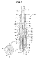
- a spark plug 100 As is seen in Fig. 1, there is provided a spark plug 100 according to an embodiment of the present invention.
- the spark plug 100 is constituted of a metal shell 1, an insulator 2, a center electrode 3 and a ground electrode 4 and the like.
- the metal shell 1 is tubular.
- the insulator 2 mates in the metal shell 1, and has a head end section 21 protruding (downward in Fig. 1) from the metal shell 1.
- the center electrode 3 mates in the insulator 2 in such a manner that a first igniter 31 is disposed at a head end (lower in Fig. 1) of the center electrode 3 and protrudes from the insulator 2.
- the ground electrode 4 has a first end (upper in Fig. 1) coupled to the metal shell 1 by welding and the like, and a second end (lower in Fig. 1) bent sideward (rightward in Fig. 1).
- the second end of the ground electrode 4 has a side face opposing the head end of the center electrode 3.
- the ground electrode 4 is formed with a second igniter 32 which is so opposed to the first igniter 31 as to form a spark discharge gap G therebetween.
- the ground electrode 4 and a body section 3a (of the center electrode 3) are made of nickel alloy and the like.
- a core material 3b made of Cu, Cu alloy or the like is embedded for encouraging heat radiation.
- the metal shell 1 is made of a metal such as low carbon steel, and is shaped substantially into a cylinder.
- the metal shell 1 constitutes a housing of the spark plug 100.
- the metal shell 1 has an outer periphery which is formed with a screw section 7 used for mounting the spark plug 100 to an engine block (not shown in Fig. 1).
- the metal shell 1 is formed with a tool engagement section 1e engaging with a tool such as a spanner, a wrench and the like which are used for mounting the metal shell 1 to the spark plug 100.
- the tool engagement section 1e has a cross section (when viewed in a direction along an axial line O of the insulator 2) which is shaped substantially into a hexagon.
- the insulator 2 is a sintered body made of an alumina ceramic.
- the insulator 2 is formed with a through hole 6 extending in a direction along the axial line O.
- the insulator 2 has a first end (lower in Fig. 1) to which the center electrode 3 is fixed, and a second end (upper in Fig. 1) to which a terminal metal fitting 13 is fixed.
- a resistor 15 which is interposed between the center electrode 3 and the terminal metal fitting 13.
- the resistor 15 has a first end (lower in Fig. 1) which is electrically connected to the center electrode 3 by way of a first conductive glass seal layer 16, and a second end (upper in Fig.
- the resistor 15 is made of a resistor composition which uses a mixed powder as a raw material, wherein the mixed powder includes a glass powder and a conductive material powder (and if necessary, a ceramic powder other than the glass).
- a front side is defined as a side having the center electrode 3 (lower in Fig. 1), while a rear side is defined as a side having the terminal metal fitting 13 (upper in Fig. 1).
- a protrusion section 2e protruding outward circumferentially in a form of a flange.
- the insulator 2 has a body section 2b which is disposed on the rear side of the protrusion section 2e.
- the body section 2b is smaller in diameter than the protrusion section 2e.
- the insulator 2 has a first shaft section 2g on the front side of the protrusion section 2e.
- the first shaft section 2g is smaller in diameter than the protrusion section 2e.
- the second shaft section 2i is smaller in diameter than the first shaft section 2g.
- the corrugation section 2c has an outer periphery which is formed with a glaze layer 2d.
- An outer periphery of the first shaft section 2g is shaped substantially into a cylinder.
- An outer periphery of the second shaft section 2i is shaped substantially into a cone which is more reduced in diameter toward the head end section 21 of the insulator 2.
- the through hole 6 of the insulator 2 has a first section 6a and a second section 6b.
- the first section 6a into which the center electrode 3 is inserted is shaped substantially into a cylinder.
- the second section 6b which is also shaped substantially into a cylinder is disposed on the rear side (upper in Fig. 1) of the first section 6a, and is larger in diameter than the first section 6a.
- the terminal metal fitting 13 and the resistor 15 are housed in the second section 6b, while the center electrode 3 is inserted into the first section 6a.
- the first section 6a and the second section 6b of the through hole 6 are connected with each other in the first shaft section 2g.
- the thus connected position is formed with a receptacle face 6c for receiving the convex section 3c of the center electrode 3.
- the receptacle face 6c is shaped substantially into a taper or a roundness.
- a connector section 2h connecting the first shaft section 2g and the second section shaft section 2i defines an outer periphery which is shaped substantially into a step, as is seen in a partly enlarged view of Fig. 1.
- the connector section 2h may engage with a convex section 1c formed on an inner periphery of the metal shell 1, to thereby prevent removal of the insulator 2 from the metal shell 1 in the direction of the axial line O.
- a second line packing 62 between the outer periphery of the insulator 2 and an inner periphery of a space defined on the rear side of the metal shell 1.
- the second line packing 62 shaped substantially into a ring may engage with the rear side of the protrusion section 2e shaped substantially into the flange.
- a first line packing 60 on the further rear side of the metal shell 1, there is provided a first line packing 60 in such a manner that the second line packing 62 and the first line packing 60 interpose therebetween a packed bed 61 which is made of talc and the like.
- the metal shell 1 can be fixed to the insulator 2 in the following steps:
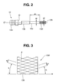
- Fig. 2 shows a general view of the terminal metal fitting 13.
- the terminal metal fitting 13 is, as a whole, shaped substantially into a round rod.
- the terminal metal fitting 13 defines an axial line O' which is substantially consistent with the axial line O (see Fig. 1) of the insulator 2.
- the terminal metal fitting 13 is constituted of a terminal section 13a, a large diameter section 13b, a small diameter section 13c, and a front end section 13d.
- the terminal section 13a is shaped substantially into a barrel, and so engages with a mouth piece of a plug cap (not shown in Fig. 1 or Fig. 2) as to secure electric conductivity.
- the large diameter section 13b is disposed in the through hole 6 of the insulator 2, and extends from the terminal section 13a toward a head end of the terminal metal fitting 13.
- the large diameter section 13b defines a front end which is reduced in diameter.
- the small diameter section 13c extends frontward from the above front end (reduced in diameter) of the large diameter section 13b.
- the front end section 13d is slightly larger in diameter than the small diameter section 13c, and has an outer periphery which is machined through a knurling.
- the terminal section 13a is, what is called, a united part of the terminal metal fitting 13.
- a spark plug having a screw type terminal section 13a (namely, removable terminal section 13a).
- the front end section 13d of the terminal metal fitting 13 is a section that is embedded in the second conductive glass seal layer 17.
- the small diameter section 13c is so formed as to extend rearward from the front end section 13d.
- the small diameter section 13c has a front side (right in Fig. 2) which is partly embedded in the second conductive glass seal layer 17, like the front end section 13d.
- the terminal section 13a has a front side defining a seal face Q which abuts on a rear end face of the insulator 2.
- the seal face Q is so formed as to as to surround the axial line O'.
- Used for the terminal metal fitting 13 includes an alloy steel SCM435 that is specified by JIS-G4025, where JIS stands for Japanese Industrial Standard.
- the alloy steel SCM435 can be prevented from becoming soft in a heating temperature range (for example, max. 930° C to max. 950° C) which is caused in a glass sealing step. Moreover, the above alloy steel SCM435 can be hardened without rapid quenching.
- Japanese Patent Unexamined Publication No. Heisei 4(1922)-133283 ⁇ equivalent of Japanese Patent Examined Publication No. P3099240 ⁇ and Japanese Patent Unexamined Publication No. P2001-185324A disclose technologies usable for making the terminal metal fitting 13.
- the small diameter section 13c and the front end section 13d are deflected in such a manner as to curve the axial line O', to thereby prevent a pressure (which is applied from a press fitting device) from concentrating on a head end face 13k (see Fig. 2) of the front end section 13d.
- the above operation can help prevent cracks which may be caused, by way of the resistor 15, the first conductive glass seal layer 16 and the second conductive glass seal layer 17, in the vicinity of a boundary between the first shaft section 2g and the second shaft section 2i.
- the outer diameter d1 of the small diameter section 13c preferably has a difference in a range from 1.0 mm to 1.4 mm from an inner diameter D6 (see Fig. 4) of the second section 6b of the through hole 6 of the insulator 2.
- the above difference (in the range from 1.0 mm to 1.4) allows the terminal metal fitting 13 to have proper deflection even with Vickers hardness kept in a range from 150 Hv to 300 Hv.
- the knurling of the front end section 13d is carried out in the following steps:
- the adjacent two knurled slots S define a knurled slot distance P.
- a section covering the front end section 13d causes such a plastic deformation as to change (increase) the diameter of the front end section 13d.
- the straight rod as described above can be replaced otherwise. More specifically, another rod can secure in advance a proper difference in diameter between the small diameter section 13c and the front end section 13d.
- the plural knurled slots S thus formed through the knurling are in parallel with each other.
- the predetermined angle ⁇ 1 defined by the knurled slot S as is seen in Fig. 3 is preferably in a range from 15° to 25° relative to a reference line H which is perpendicular to the axial line O'.
- the predetermined angle ⁇ 1 smaller than 15° is not preferred for the following cause:
- Conductive glass powders having mean diameter 1/6 to 1/3 as large as the knurled slot distance P is preferred for sufficiently filling the glass seal material in each of the knurled slots S.
- Forming the second conductive glass seal layer 17 using the above conductive glass powders (having mean diameter 1/6 to 1/3 as large as the knurled slot distance P) can increase the joint strength between the insulator 2 and the terminal metal fitting 13.
- the predetermined angle ⁇ 1 larger than 25° is not preferred for the following cause:
- a surface roughing can be adopted for machining the front end section 13d of the terminal metal fitting 13.
- Fig. 4 shows the insulator 2 exemplifying dimensions as follows:
- the insulator 2 for the spark plug 100 (M12) under the present invention may have the following dimensions:
- Dimensions of the terminal metal fitting 13 are preferably adjusted in accordance with the above dimensions of the insulator 2 for the spark plug 100 (M12). More specifically, described as follows:
- difference between the inner diameter D6 (of the second section 6b of the through hole 6 of the insulator 2) and the outer diameter d2 (of the front end section 13d) is preferably in a range from 0.3 mm to 0.8 mm.
- the above difference can be defined as a gap between the inner diameter D6 and the outer diameter d2.
- the glass seal material of the second conductive glass seal layer 17 is unlikely to rise, resulting in an excessive stress applied to the insulator 2.
- the difference between the inner diameter D6 and the outer diameter d2 is too small (namely, smaller than 0.3 mm)
- the pressure cannot be applied to the insulator 2 sufficiently, to thereby fail to make the glass sealing strong.
- the outer diameter d2 of the front end section 13d is knurled as described above, and is defined as a vertical distance between a "line” including a crest and “another line” including an opposing crest of a thread of a normal screw (Hereinabove, the "line” and the “another line” are in parallel with a center axis of the normal screw).
- Each of the first conductive glass seal layer 16 and the second conductive glass seal layer 17 includes a base glass, a conductive filler and an insulative filler.
- the base glass is mainly made of an oxide such as borosilicate.
- the conductive filler is mainly made of one kind of metal powder or two and more kinds of metal powders, selected from a group consisting of Cu, Fe and the like.
- the insulative filler can be one kind of oxide inorganic material or two and more kinds of oxide inorganic materials, selected from a group consisting of ⁇ -eucryptite, ⁇ -spodumene, keathite, silica, mullite, cordierite, zircon and aluminum titanate, and the like.
- a first conductive glass powder layer for the first conductive glass seal layer 16
- a composition powder layer for the resistor 15
- a second conductive glass powder layer for the second conductive glass seal layer 17
- the terminal metal fitting 13 is disposed on the rear side of the through hole 6.
- the thus formed assembly is inserted into a heating furnace, and thereby heated at a predetermined temperature of 700° C to 950° C.
- the terminal metal fitting 13 is press fitted into the through hole 6 from the side opposite to the center electrode 3's side in the direction of the axial line O, to thereby compress the accumulated layers ⁇ namely, the first conductive glass powder layer (for the first conductive glass seal layer 16), the composition powder layer (for the resistor 15) and the second conductive glass powder layer (for the second conductive glass seal layer 17) ⁇ in the direction of the axial line O.
- each of the accumulated layers can be compressed and sintered, to thereby form, respectively, the first conductive glass seal layer 16, the resistor 15 and the second conductive glass seal layer 17.
- the above wraps up the glass sealing step.
- blending (proportion) and grain diameter of each of the base glass powder, the metal powder (conductive filler powder), and the insulative filler powder are preferably so adjusted as to allow the conductive glass powder to have an apparent softening (deformation) point in a range from 500° C to 1000° C.
- the softening point is lower than 500° C, the first conductive glass seal layer 16 and the second conductive glass seal layer 17 may feature insufficient heat resistance; while the softening point higher than 1000° C may be responsible for decrease in sealing performance.
- the softening point can be determined in the following steps:
- the applied glaze slurry layer is baked simultaneously in the glass sealing step, to thereby form the glaze layer 2d.
- the conductive glass powder has a preferable grain diameter (mean) in a range from 1/5 to 1/2 as large as a difference between the outer diameter d2 (of the front end section 13d of the terminal metal fitting 13) and the inner diameter D6 (of the second section 6b of the through hole 6 of the insulator 2).
- the mean grain diameter of the conductive glass powder is 150 ⁇ m.
- the conductive glass powder having the grain diameter (mean) less than 1/5 as large as the difference between the outer diameter d2 and the inner diameter D6 may be responsible for shortage of the pressure, resulting in decrease in the joint strength (between the insulator 2 and the terminal metal fitting 13).
- the glass powder having the grain diameter (mean) more than 1/2 as large as the difference between the outer diameter d2 and the inner diameter D6 is less likely to flow an area between the outer diameter d2 and the inner diameter D6 in the glass sealing step.
- the glass powder (more specifically, the second conductive glass seal layer 17) may find it difficult to adhere to entire part of the front end section 13d (and the front side of the small diameter section 13c).
- the assembly formed after the glass sealing step as described above is then fitted with the metal shell 1, the ground electrode 4 and the like, to thereby complete the spark plug 100 as is seen in Fig. 1.
- the spark plug 100 is mounted to the engine block (not shown in Fig. 1) via the screw section 7, and thereby used as an ignition source of the mixture supplied to a combustion chamber of the engine.
- the spark plug 100 shown in Fig. 1 was made in the following conditions:
- Each of the "Good” samples (no cracks found) of the insulator 2 was assembled with the metal shell 1, the ground electrode 4 and the like, to thereby obtain the spark plug 100 under the present invention, as is seen in Fig. 1.
- the thus obtained spark plug 100 was subjected to a load-life test specified by JIS-B8031 (1995) for testing durability and life time of the resistor 15 in the spark plug 100.
- JIS-B8031 (1995) was carried out.
- Table 1 shows acceptance criteria of the JIS-B8031 (1995) and of the acceleration test pursuant to JIS-B8031 (1995).
- Table 2 sums up results of the tests on productivity and load-life. In addition, Table 2 shows total determination based on the results of the tests on productivity and load-life. Evaluation No. Difference: D6 - d1 (mm) Material (hardness after glass sealing steps) (Hv) Determination Total Productivity ("Good” ratio) Load-life 1-1 0.9 150 ⁇ D D A 1-2 1.0 150 ⁇ B B A 1-3 1.1 150 ⁇ A A A 1-4 1.2 150 ⁇ B A B 1-5 1.3 150 ⁇ B A B 1-6 1.4 150 ⁇ B A B 1-7 1.5 150 ⁇ D A D
- Table 2 can be interpreted as follows:
- the spark plug 100 shown in Fig. 1 was made in the following conditions:
- Table 3 shows total determination based on the results of the tests on productivity and load-life. Evaluation No. Difference: D6 - d2 (mm) Material (hardness after glass sealing steps) (Hv) Determination Total Productivity ("Good” ratio) Load-life 2-1 0.2 150 ⁇ C C A 2-2 0.3 150 ⁇ B B A 2-3 0.5 150 ⁇ A A A 2-4 0.7 150 ⁇ B A B 2-5 0.8 150 ⁇ B A B 2-6 0.9 150 ⁇ C A C
- Table 3 can be interpreted as follows:
- the spark plug 100 shown in Fig. 1 was made in the following conditions:
- Table 4 shows the total determination only. Evaluation No. Predetermined angle ⁇ 1:(°) Difference: D6 - d1 (mm) Difference: D6 - d2 (mm) Material (hardness after glass sealing steps) (Hv) Determination 3-1 20 1.1 0.5 150 ⁇ A 3-2 45 1.1 0.5 150 ⁇ B
- the terminal section 13a (of the terminal metal fitting 13) having the Vickers hardness of 150 Hv or over contributes to prevention of wear.
- the embodiment of the present invention can provide the small spark plug 100 (M12) having the insulator 2, the terminal metal fitting 13 and the center electrode 3 which are joined together securely.
- the embodiment of the present invention is most preferable to the spark plug having the screw diameter of 12 mm (M12), but also applicable to the smaller screw diameter of 10 mm (M10) and the like.
Landscapes
- Spark Plugs (AREA)
Abstract
Description
- A through hole having a first end side and a second end side (opposite to the first end side) is formed in a direction of an axial line of an insulator. A center electrode is inserted for fixation into the first end side of the through hole, while a terminal metal fitting is inserted for fixation into the second end side of the through hole. In the through hole, a resistor is interposed between the center electrode and the terminal metal fitting.
- When the spark plug having the terminal metal fitting that is insufficient in hardness is mounted to the internal combustion engine, the terminal metal fitting may cause a wear due to a friction with a mouth piece of a plug cap. The thus caused wear may lead to failures such as flash over (attributable to wear powder), increased contact resistance (between the terminal section and the mouth piece of the plug cap), and the like.
- When the engine vibration and the like may apply a stress to the terminal metal fitting, the thus applied stress cannot be dispersed effectively, resulting in concentration of the stress in a specific section of an insulator. The thus concentrated stress may break the insulator.
- When the terminal metal fitting 13 is embedded in the second conductive
glass seal layer 17, a glass seal material is less likely to rise toward the rear side of theterminal metal fitting 13. This may also cause shortage of filling the glass seal material in each of the knurled slots S.
- The pressure applied to the second conductive
glass seal layer 17 when press fitting the terminal metal fitting 13 into theinsulator 2 may become insufficient. The thus applied small pressure may render the glass sealing insufficient, thereby decreasing the joint strength between theinsulator 2 and theterminal metal fitting 13.
| 1) Overall length L1 | about 60 mm. |
| 2) Length L2 | about 10 mm. |
| 3) Length L3 | about 14 mm. |
| 4) Outer diameter D1 | about 11 mm. |
| 5) Outer diameter D2 | about 13 mm. |
| 6) Outer diameter D3 | about 7.3 mm. |
| 7) Outer diameter D4 | 5.3 mm. |
| 8) Outer diameter D5 | 4.3 mm. |
| 9) Inner diameter D6 | 3.9 mm. |
| 10) Inner diameter D7 | 2.6 mm. |
| 11) Thickness t1 | 1.7 mm. |
| 12) Thickness t2 | 1.4 mm. |
| 13) Thickness t3 | 0.9 mm. |
| 14) Arithmetic mean thickness tA | 1.15 mm. |
- At first, the insulator 2 (having dimensions listed in [Dimensions of
insulator 2] above) for the spark plug 100 (M12) was made. Herein, the inner
diameter D6 of the
second section 6b of the throughhole 6 is fixed at 3.9 mm. The above alloy steel SCM435 (herein, however, alloy steel SCM435 Cr-Mo) was used for making the terminal metal fittings 13 (see in Fig. 2) having various dimensions. More specifically, the inner diameter D6 (of thesecond section 6b of the throughhole 6 of the insulator 2) was varied in dimensions provided that the inner diameter D6 should have a difference from the outer diameter d1 (of thesmall diameter section 13c) in a range from 0.9 mm to 1.5 mm. Herein, each of the knurled slots S formed in thefront end section 13d has the predetermined angle 1 of 20°. The thus prepared terminal metal fitting 13 was subjected to the glass sealing step as described above, for assembly to theinsulator 2. The alloy steel SCM435 Cr-Mo is the one that can keep its Vickers hardness 150 Hv or over after the glass sealing step.
- An area corresponding to the
front end section 13d are differentiated in advance from an area corresponding to thesmall diameter section 13c. In addition, the outer diameter d2 has a fixed dimension of 3.4 mm.
- A:
- 99% ≤ "Good" ratio.
- B:
- 90% ≤ "Good" ratio < 99%.
- C:
- 80% ≤ "Good" ratio < 90%.
- D:
- "Good" ratio < 80%.
| Acceptance criteria of load-life test | |||
| JIS-B8031 (1995) | Increased resistance after JIS-B8031 (1995) | Acceleration test pursuant to JIS-B8031 (1995) | |
| A | Acceptable | Not found | Acceptable |
| B | Acceptable | Not found | Not acceptable |
| C | Acceptable | Found | Not acceptable |
| D | Not acceptable | Not available | Not available |
Checks resistance change after a test for 250 hr. at normal temperature.
Checks for increased resistance after JIS- B8031 (1995).
- The resistance increased after JIS-B8031 (1995) is not preferable since it is likely to cause resistance change of 30% or over (not acceptable) in the continued test.
Checks for resistance change after a stringent (accelerated) operating test {pursuant to JIS-B8031 (1995)} for 250 hr. at 350° C. Passing the stringent operating test is a proof of improved reliability.
| Evaluation No. | Difference: D6 - d1 (mm) | Material (hardness after glass sealing steps) (Hv) | Determination | ||
| Total | Productivity ("Good" ratio) | Load-life | |||
| 1-1 | 0.9 | 150 < | D | D | A |
| 1-2 | 1.0 | 150 < | B | B | A |
| 1-3 | 1.1 | 150 < | A | A | A |
| 1-4 | 1.2 | 150 < | B | A | B |
| 1-5 | 1.3 | 150 < | B | A | B |
| 1-6 | 1.4 | 150 < | B | A | B |
| 1-7 | 1.5 | 150 < | D | A | D |
- The difference between the inner diameter D6 (of the
second section 6b of the throughhole 6 of the insulator 2) and the outer diameter d1 (of thesmall diameter section 13c of the terminal metal fitting 13) was fixed at 1.1 mm. The outer diameter d2 (of thefront end section 13d) was varied in a range from 3.0 mm to 3.7 mm. Theinsulator 2 used for the example 1 was also used for the example 2, with the difference between the inner diameter D6 and the outer diameter d2 in a range from 0.2 mm to 0.9 mm, as is seen in Table 3 (to be described afterward). Thespark plug 100 was assembled in the same manner as that of the example 1. Then, like the example 1, the tests on productivity and load-life were carried out according to the example 2. Table 3 sums up results of the tests according to the example 2.
| Evaluation No. | Difference: D6 - d2 (mm) | Material (hardness after glass sealing steps) (Hv) | Determination | ||
| Total | Productivity ("Good" ratio) | Load-life | |||
| 2-1 | 0.2 | 150 < | C | C | A |
| 2-2 | 0.3 | 150 < | B | B | A |
| 2-3 | 0.5 | 150 < | A | A | A |
| 2-4 | 0.7 | 150 < | B | A | B |
| 2-5 | 0.8 | 150 < | B | A | B |
| 2-6 | 0.9 | 150 < | C | A | C |
- The outer diameter d1 (mean) of the
small diameter section 13c of the terminal metal fitting 13 is fixed at 2.8 mm. The outer diameter d2 of thefront end section 13d is fixed at 3.4 mm. The predetermined angle 1 defined between the knurled slot S (to be formed in thefront end section 13d) and the reference line H is 20° and 45°. Theinsulator 2 used for the example 1 was also used for the example 3. Thespark plug 100 was assembled in the same manner as that of the example 1. Then, like the example 1, the tests on productivity and load-life were carried out according to the example 3. Table 4 sums up results of the tests according to the example 3.
| Evaluation No. | Predetermined angle 1:(°) | Difference: D6 - d1 (mm) | Difference: D6 - d2 (mm) | Material (hardness after glass sealing steps) (Hv) | Determination |
| 3-1 | 20 | 1.1 | 0.5 | 150 < | A |
| 3-2 | 45 | 1.1 | 0.5 | 150 < | B |
Claims (20)
- A spark plug (100), comprising:a metal shell (1) defining a front side having an outer periphery formed with a screw section (7) which has a nominal size smaller than or equal to M12;a center electrode (3);a conductive seal layer (16,17);a terminal metal fitting (13) fixed to the center electrode (3) by way of the conductive seal layer (16, 17), the terminal metal fitting (13) having a Vickers hardness in a range from 150 Hv to 300 Hv, the terminal metal fitting (13) including:a front end section (13d) having an outer diameter (d2), and embedded in the conductive seal layer (17), anda small diameter section (13c) disposed on a rear side of the front end section (13d) and having an outer diameter (d1) which is smaller than the outer diameter (d2) of the front end section (13d); andan insulator (2) formed with a through hole (6) which extends in a direction of an axial line (O) of the insulator (2) and houses the center electrode (3), the conductive seal layer (16, 17) and the terminal metal fitting (13), the insulator (2) having an outer periphery where the metal shell (1) is disposed, the insulator (2) defining the following sides in the direction of the axial line (O) of the insulator (2):i) a front side where the center electrode (3) is disposed, andii) a rear side where the terminal metal fitting (13) is disposed,
the through hole (6) having an inner diameter (D6) which is different from the outer diameter (d1) of the small diameter section (13c) of the terminal metal fitting (13) in a range from 1.0 mm to 1.4 mm. - The spark plug (100) as claimed in claim 1, wherein
the inner diameter (D6) of the through hole (6) of the insulator (2) is different from the outer diameter (d2) of the front end section (13d) of the terminal metal fitting (13) in a range from 0.3 mm to 0.8 mm. - The spark plug (100) as claimed in claim 2, wherein
the inner diameter (D6) of the through hole (6) of the insulator (2) is larger than the outer diameter (d1) of the small diameter section (13c) of the terminal metal fitting (13) in the range from 1.0 mm to 1.4 mm, and
the inner diameter (D6) of the through hole (6) of the insulator (2) is larger than the outer diameter (d2) of the front end section (13d) of the terminal metal fitting (13) in the range from 0.3 mm to 0.8 mm. - The spark plug (100) as claimed in one of claim 1 and claim 2, wherein
the front end section (13d) of the terminal metal fitting (13) has an outer periphery which is knurled. - The spark plug (100) as claimed in claim 4, wherein
knurling the outer periphery of the front end section (13d) of the terminal metal fitting (13) forms a plurality of knurled slots (S) which are parallel with each other, and
an angle (1) is so adjusted to vary in a range from 15° to 25° between one of the knurled slots (S) and a reference line (H) perpendicular to the axial line (O) of the insulator (2). - The spark plug (100) as claimed in claim 1, wherein
the through hole (6) of the insulator (2) has a first section (6a) and a second section (6b),
the first section (6a) into which the center electrode (3) is inserted is shaped substantially into a cylinder,
the second section (6b) which is also shaped substantially into a cylinder is disposed on a rear side of the first section (6a), and is larger in diameter than the first section (6a), and
the terminal metal fitting (13) and a resistor (15) are housed in the second section (6b). - The spark plug (100) as claimed in claim 1, wherein
the terminal metal fitting (13) further includes a terminal section (13a) which is disposed at a rearmost position of the terminal metal fitting (13) in such a manner as to protrude rearward from the insulator (2), and
the Vickers hardness in the range from 150 Hv to 300 Hv is measured in the terminal section (13a). - The spark plug (100) as claimed in claim 1, wherein
the screw section (7) of the metal shell (1) has the nominal size of M10. - The spark plug (100) as claimed in one of claim 1 and claim 2, wherein
the front end section (13d) of the terminal metal fitting (13) has an outer periphery which is machined by a surface roughing. - A spark plug (100), comprising:a metal shell (1);a center electrode (3);a conductive seal layer (16, 17);a terminal metal fitting (13) fixed to the center electrode (3) by way of the conductive seal layer (16, 17), the terminal metal fitting (13) including:a front end section (13d) having an outer diameter (d2), and embedded in the conductive seal layer (17), anda small diameter section (13c) disposed on a rear side of the front end section (13d) and having an outer diameter (d1) which is smaller than the outer diameter (d2) of the front end section (13d) in a range from 0.3 mm to 0.7 mm, the small diameter section (13c) defining a front side which is partly embedded in the conductive seal layer (17); andan insulator (2) formed with a through hole (6) which extends in a direction of an axial line (O) of the insulator (2) and houses the center electrode (3), the conductive seal layer (16, 17) and the terminal metal fitting (13), the insulator (2) having an outer periphery where the metal shell (1) is disposed, the insulator (2) defining the following sides in the direction of the axial line (O) of the insulator (2):i) a front side where the center electrode (3) is disposed, andii) a rear side where the terminal metal fitting (13) is disposed.
- The spark plug (100) as claimed in claim 10, wherein
the conductive seal layer (16, 17) is made of a conductive glass powder having a mean diameter 1/5 to 1/2 as large as a difference between an inner diameter (D6) of the through hole (6) and the outer diameter (d2) of the front end section (13d) of the terminal metal fitting (13). - The spark plug (100) as claimed in one of claim 10 and claim 11, wherein
the front end section (13d) of the terminal metal fitting (13) has an outer periphery which is knurled. - The spark plug (100) as claimed in claim 12, wherein
the conductive seal layer (16, 17) is made of a conductive glass powder having a mean diameter 1/6 to 1/3 as large as a distance between two of knurled slots (S) formed through the knurling which is carried out on the outer periphery of the front end section (13d) of the terminal metal fitting (13). - The spark plug (100) as claimed in one of claim 12 and claim 13, wherein
knurling the outer periphery of the front end section (13d) of the terminal metal fitting (13) forms a plurality of knurled slots (S) which are parallel with each other, and
an angle (1) is so adjusted to vary in a range from 15° to 25° between one of the knurled slots (S) and a reference line (H) perpendicular to the axial line (O) of the insulator (2). - The spark plug (100) as claimed in claim 10 to claim 14, wherein
the terminal metal fitting (13) has a Vickers hardness in a range from 150 Hv to 300 Hv. - The spark plug (100) as claimed in any one of claim 10 to claim 15, wherein
the through hole (6) of the insulator (2) has an inner diameter (D6) which is different from the outer diameter (d1) of the small diameter section (13c) in a range from 1.0 mm to 1.4 mm. - The spark plug (100) as claimed in any one of claim 11 to claim 16, wherein
the inner diameter (D6) of the through hole (6) of the insulator (2) is different from the outer diameter (d2) of the front end section (13d) of the terminal metal fitting (13) in a range from 0.3 mm to 0.8 mm. - The spark plug (100) as claimed in claim 17, wherein
the inner diameter (D6) of the through hole (6) of the insulator (2) is larger than the outer diameter (d1) of the small diameter section (13c) of the terminal metal fitting (13) in the range from 1.0 mm to 1.4 mm, and
the inner diameter (D6) of the through hole (6) of the insulator (2) is larger than the outer diameter (d2) of the front end section (13d) of the terminal metal fitting (13) in the range from 0.3 mm to 0.8 mm. - The spark plug (100) as claimed in claim 15, wherein
the terminal metal fitting (13) further includes a terminal section (13a) which is disposed at a rearmost position of the terminal metal fitting (13) in such a manner as to protrude rearward from the insulator (2), and
the Vickers hardness in the range from 150 Hv to 300 Hv is measured in the terminal section (13a). - The spark plug (100) as claimed in one of claim 10 and claim 11, wherein
the front end section (13d) of the terminal metal fitting (13) has an outer periphery which is machined by a surface roughing.
Priority Applications (1)
| Application Number | Priority Date | Filing Date | Title |
|---|---|---|---|
| EP07007831A EP1801941B1 (en) | 2001-10-31 | 2002-10-29 | Spark Plug |
Applications Claiming Priority (2)
| Application Number | Priority Date | Filing Date | Title |
|---|---|---|---|
| JP2001335110 | 2001-10-31 | ||
| JP2001335110A JP3795374B2 (en) | 2001-10-31 | 2001-10-31 | Spark plug |
Related Child Applications (1)
| Application Number | Title | Priority Date | Filing Date |
|---|---|---|---|
| EP07007831A Division EP1801941B1 (en) | 2001-10-31 | 2002-10-29 | Spark Plug |
Publications (3)
| Publication Number | Publication Date |
|---|---|
| EP1309052A2 true EP1309052A2 (en) | 2003-05-07 |
| EP1309052A3 EP1309052A3 (en) | 2006-04-19 |
| EP1309052B1 EP1309052B1 (en) | 2009-03-11 |
Family
ID=19150136
Family Applications (2)
| Application Number | Title | Priority Date | Filing Date |
|---|---|---|---|
| EP02024458A Expired - Lifetime EP1309052B1 (en) | 2001-10-31 | 2002-10-29 | Spark plug |
| EP07007831A Expired - Lifetime EP1801941B1 (en) | 2001-10-31 | 2002-10-29 | Spark Plug |
Family Applications After (1)
| Application Number | Title | Priority Date | Filing Date |
|---|---|---|---|
| EP07007831A Expired - Lifetime EP1801941B1 (en) | 2001-10-31 | 2002-10-29 | Spark Plug |
Country Status (4)
| Country | Link |
|---|---|
| US (1) | US6680561B2 (en) |
| EP (2) | EP1309052B1 (en) |
| JP (1) | JP3795374B2 (en) |
| DE (2) | DE60231463D1 (en) |
Cited By (8)
| Publication number | Priority date | Publication date | Assignee | Title |
|---|---|---|---|---|
| EP1641093A1 (en) * | 2004-09-24 | 2006-03-29 | Ngk Spark Plug Co., Ltd. | Spark plug |
| CN102549861A (en) * | 2009-09-25 | 2012-07-04 | 日本特殊陶业株式会社 | Spark plug and process for producing spark plug |
| WO2013086479A1 (en) * | 2011-12-09 | 2013-06-13 | Federal-Mogul Ignition Company | Improvements to insulator strength by seat geometry |
| EP2624383A4 (en) * | 2010-10-01 | 2014-02-19 | Ngk Spark Plug Co | IGNITION CANDLE |
| EP2469555A4 (en) * | 2009-09-18 | 2014-04-16 | Ngk Spark Plug Co | IGNITION CANDLE |
| CN104048688A (en) * | 2014-06-10 | 2014-09-17 | 陕西航空电气有限责任公司 | Novel ion flame detector insulator assembly |
| CN105449527A (en) * | 2014-09-24 | 2016-03-30 | 日本特殊陶业株式会社 | Spark plug |
| EP2672588A4 (en) * | 2011-02-02 | 2016-11-02 | Ngk Spark Plug Co | IGNITION CANDLE |
Families Citing this family (19)
| Publication number | Priority date | Publication date | Assignee | Title |
|---|---|---|---|---|
| US7164225B2 (en) * | 2003-09-11 | 2007-01-16 | Ngk Spark Plug Co., Ltd. | Small size spark plug having side spark prevention |
| JP2005166291A (en) * | 2003-11-28 | 2005-06-23 | Denso Corp | Spark plug |
| JP2005183177A (en) * | 2003-12-19 | 2005-07-07 | Ngk Spark Plug Co Ltd | Spark plug |
| US20050168121A1 (en) * | 2004-02-03 | 2005-08-04 | Federal-Mogul Ignition (U.K.) Limited | Spark plug configuration having a metal noble tip |
| JP4357993B2 (en) * | 2004-03-05 | 2009-11-04 | 日本特殊陶業株式会社 | Spark plug |
| JP2006100250A (en) * | 2004-08-31 | 2006-04-13 | Denso Corp | Spark plug for internal combustion engine and ignition device using the same |
| US7606040B2 (en) * | 2004-09-03 | 2009-10-20 | Entorian Technologies, Lp | Memory module system and method |
| JP4520320B2 (en) * | 2005-01-28 | 2010-08-04 | 日本特殊陶業株式会社 | Spark plug and method for manufacturing the same |
| US7557496B2 (en) * | 2005-03-08 | 2009-07-07 | Ngk Spark Plug Co., Ltd. | Spark plug which can prevent lateral sparking |
| JP4758124B2 (en) * | 2005-03-31 | 2011-08-24 | 日本特殊陶業株式会社 | Spark plug |
| JP4625416B2 (en) * | 2006-03-21 | 2011-02-02 | 日本特殊陶業株式会社 | Spark plug |
| BRPI0713677A2 (en) * | 2006-06-19 | 2012-10-23 | Federal Mogul Corp | spark plug for a spark ignition combustion event |
| JP4473316B2 (en) | 2007-03-30 | 2010-06-02 | 日本特殊陶業株式会社 | Spark plug for internal combustion engine |
| EP1976078B1 (en) | 2007-03-30 | 2011-09-14 | NGK Spark Plug Company Limited | Spark plug for internal combustion engine |
| JP2009259775A (en) | 2008-03-19 | 2009-11-05 | Ngk Spark Plug Co Ltd | Insulator for spark plug and method of manufacturing spark plug |
| JP5616858B2 (en) * | 2011-08-17 | 2014-10-29 | 日本特殊陶業株式会社 | Spark plug |
| DE102014226107A1 (en) * | 2014-12-16 | 2016-06-16 | Robert Bosch Gmbh | Spark plugs with center electrode |
| JP2018032541A (en) * | 2016-08-25 | 2018-03-01 | 日本特殊陶業株式会社 | Ignition plug |
| DE102017205828A1 (en) * | 2017-04-05 | 2018-10-11 | Robert Bosch Gmbh | Spark plug with improved tightness |
Family Cites Families (6)
| Publication number | Priority date | Publication date | Assignee | Title |
|---|---|---|---|---|
| JPH0399240A (en) | 1989-09-12 | 1991-04-24 | Isuzu Motors Ltd | Torque detector |
| JPH0447691A (en) | 1990-06-12 | 1992-02-17 | Ngk Spark Plug Co Ltd | Terminal seal portion of spark plug |
| JP3099240B2 (en) | 1990-09-25 | 2000-10-16 | 日本特殊陶業株式会社 | Terminal electrode for spark plug |
| GB2276207B (en) * | 1993-03-18 | 1996-09-04 | Nippon Denso Co | A spark plug and a method of producing the same |
| US6078129A (en) * | 1997-04-16 | 2000-06-20 | Denso Corporation | Spark plug having iridium containing noble metal chip attached via a molten bond |
| JP2001185324A (en) | 2000-11-06 | 2001-07-06 | Ngk Spark Plug Co Ltd | Spark plug for internal combustion engine |
-
2001
- 2001-10-31 JP JP2001335110A patent/JP3795374B2/en not_active Expired - Fee Related
-
2002
- 2002-10-29 DE DE60231463T patent/DE60231463D1/en not_active Expired - Lifetime
- 2002-10-29 EP EP02024458A patent/EP1309052B1/en not_active Expired - Lifetime
- 2002-10-29 DE DE60235053T patent/DE60235053D1/en not_active Expired - Lifetime
- 2002-10-29 EP EP07007831A patent/EP1801941B1/en not_active Expired - Lifetime
- 2002-10-30 US US10/283,113 patent/US6680561B2/en not_active Expired - Fee Related
Cited By (16)
| Publication number | Priority date | Publication date | Assignee | Title |
|---|---|---|---|---|
| EP1641093A1 (en) * | 2004-09-24 | 2006-03-29 | Ngk Spark Plug Co., Ltd. | Spark plug |
| US7215069B2 (en) | 2004-09-24 | 2007-05-08 | Ngk Spark Plug Co., Ltd. | Spark plug |
| US8723406B2 (en) | 2009-09-18 | 2014-05-13 | Ngk Spark Plug Co., Ltd. | Spark plug |
| EP2469555A4 (en) * | 2009-09-18 | 2014-04-16 | Ngk Spark Plug Co | IGNITION CANDLE |
| US8564184B2 (en) | 2009-09-25 | 2013-10-22 | Ngk Spark Plug Co., Ltd. | Spark plug and process for producing spark plug |
| CN102549861B (en) * | 2009-09-25 | 2014-01-01 | 日本特殊陶业株式会社 | Spark plug and process for producing spark plug |
| CN102549861A (en) * | 2009-09-25 | 2012-07-04 | 日本特殊陶业株式会社 | Spark plug and process for producing spark plug |
| EP2624383A4 (en) * | 2010-10-01 | 2014-02-19 | Ngk Spark Plug Co | IGNITION CANDLE |
| EP2672588A4 (en) * | 2011-02-02 | 2016-11-02 | Ngk Spark Plug Co | IGNITION CANDLE |
| US8643263B2 (en) | 2011-12-09 | 2014-02-04 | Federal-Mogul Corporation | Insulator strength by seat geometry |
| WO2013086479A1 (en) * | 2011-12-09 | 2013-06-13 | Federal-Mogul Ignition Company | Improvements to insulator strength by seat geometry |
| CN104048688A (en) * | 2014-06-10 | 2014-09-17 | 陕西航空电气有限责任公司 | Novel ion flame detector insulator assembly |
| CN105449527A (en) * | 2014-09-24 | 2016-03-30 | 日本特殊陶业株式会社 | Spark plug |
| EP3001518A1 (en) * | 2014-09-24 | 2016-03-30 | NGK Spark Plug Co., Ltd. | Spark plug |
| CN105449527B (en) * | 2014-09-24 | 2017-06-30 | 日本特殊陶业株式会社 | Spark plug |
| US10014665B2 (en) | 2014-09-24 | 2018-07-03 | Ngk Spark Plug Co., Ltd. | Spark plug |
Also Published As
| Publication number | Publication date |
|---|---|
| JP3795374B2 (en) | 2006-07-12 |
| DE60235053D1 (en) | 2010-02-25 |
| US6680561B2 (en) | 2004-01-20 |
| EP1801941A2 (en) | 2007-06-27 |
| EP1309052A3 (en) | 2006-04-19 |
| US20030117052A1 (en) | 2003-06-26 |
| DE60231463D1 (en) | 2009-04-23 |
| EP1801941B1 (en) | 2010-01-06 |
| JP2003142224A (en) | 2003-05-16 |
| EP1801941A3 (en) | 2007-08-01 |
| EP1309052B1 (en) | 2009-03-11 |
Similar Documents
| Publication | Publication Date | Title |
|---|---|---|
| US6680561B2 (en) | Spark plug | |
| EP1022828B1 (en) | Spark plug | |
| EP2161802B1 (en) | Spark plug | |
| EP2175535B1 (en) | Spark plug for internal combustion engine | |
| EP2020713B1 (en) | Spark plug for internal combustion engine and method of manufacturing the same | |
| EP1965475B1 (en) | Spark plug and method for manufacturing spark plug | |
| US6191525B1 (en) | Spark plug | |
| EP1274157B1 (en) | Spark plug | |
| EP2028736B1 (en) | Spark plug for internal combustion engine | |
| EP2267851B1 (en) | Spark plug and method of manufacturing the same | |
| EP2493036B1 (en) | Spark plug and method for producing spark plug | |
| EP2211432B1 (en) | Spark plug for internal combustion engine | |
| EP1837964B1 (en) | Spark plug for use in an internal-combustion engine | |
| EP1341281B1 (en) | Method for manufacturing spark plug and spark plug | |
| EP2096727B1 (en) | Spark plug internal combustion engine | |
| EP3252891B1 (en) | Spark plug | |
| EP3252890B1 (en) | Spark plug | |
| EP0798833A1 (en) | Spark plug for internal combustion engine | |
| EP3477801B1 (en) | Spark plug | |
| EP3285344B1 (en) | Spark plug | |
| EP2472682B1 (en) | Spark plug for internal combustion engine and method for manufacturing same |
Legal Events
| Date | Code | Title | Description |
|---|---|---|---|
| PUAI | Public reference made under article 153(3) epc to a published international application that has entered the european phase |
Free format text: ORIGINAL CODE: 0009012 |
|
| AK | Designated contracting states |
Designated state(s): AT BE BG CH CY CZ DE DK EE ES FI FR GB GR IE IT LI LU MC NL PT SE SK TR |
|
| AX | Request for extension of the european patent |
Extension state: AL LT LV MK RO SI |
|
| PUAL | Search report despatched |
Free format text: ORIGINAL CODE: 0009013 |
|
| AK | Designated contracting states |
Kind code of ref document: A3 Designated state(s): AT BE BG CH CY CZ DE DK EE ES FI FR GB GR IE IT LI LU MC NL PT SE SK TR |
|
| AX | Request for extension of the european patent |
Extension state: AL LT LV MK RO SI |
|
| 17P | Request for examination filed |
Effective date: 20060504 |
|
| AKX | Designation fees paid |
Designated state(s): DE FR |
|
| 17Q | First examination report despatched |
Effective date: 20070307 |
|
| GRAP | Despatch of communication of intention to grant a patent |
Free format text: ORIGINAL CODE: EPIDOSNIGR1 |
|
| GRAS | Grant fee paid |
Free format text: ORIGINAL CODE: EPIDOSNIGR3 |
|
| GRAA | (expected) grant |
Free format text: ORIGINAL CODE: 0009210 |
|
| AK | Designated contracting states |
Kind code of ref document: B1 Designated state(s): DE FR |
|
| REF | Corresponds to: |
Ref document number: 60231463 Country of ref document: DE Date of ref document: 20090423 Kind code of ref document: P |
|
| PLBE | No opposition filed within time limit |
Free format text: ORIGINAL CODE: 0009261 |
|
| STAA | Information on the status of an ep patent application or granted ep patent |
Free format text: STATUS: NO OPPOSITION FILED WITHIN TIME LIMIT |
|
| 26N | No opposition filed |
Effective date: 20091214 |
|
| REG | Reference to a national code |
Ref country code: FR Ref legal event code: PLFP Year of fee payment: 15 |
|
| REG | Reference to a national code |
Ref country code: FR Ref legal event code: PLFP Year of fee payment: 16 |
|
| PGFP | Annual fee paid to national office [announced via postgrant information from national office to epo] |
Ref country code: FR Payment date: 20170918 Year of fee payment: 16 |
|
| PGFP | Annual fee paid to national office [announced via postgrant information from national office to epo] |
Ref country code: DE Payment date: 20181016 Year of fee payment: 17 |
|
| PG25 | Lapsed in a contracting state [announced via postgrant information from national office to epo] |
Ref country code: FR Free format text: LAPSE BECAUSE OF NON-PAYMENT OF DUE FEES Effective date: 20181031 |
|
| REG | Reference to a national code |
Ref country code: DE Ref legal event code: R119 Ref document number: 60231463 Country of ref document: DE |
|
| PG25 | Lapsed in a contracting state [announced via postgrant information from national office to epo] |
Ref country code: DE Free format text: LAPSE BECAUSE OF NON-PAYMENT OF DUE FEES Effective date: 20200501 |