EP1309045A1 - A bulb socket and a method for mounting it - Google Patents
A bulb socket and a method for mounting it Download PDFInfo
- Publication number
- EP1309045A1 EP1309045A1 EP02024516A EP02024516A EP1309045A1 EP 1309045 A1 EP1309045 A1 EP 1309045A1 EP 02024516 A EP02024516 A EP 02024516A EP 02024516 A EP02024516 A EP 02024516A EP 1309045 A1 EP1309045 A1 EP 1309045A1
- Authority
- EP
- European Patent Office
- Prior art keywords
- main body
- bulb
- socket
- sealing member
- socket main
- Prior art date
- Legal status (The legal status is an assumption and is not a legal conclusion. Google has not performed a legal analysis and makes no representation as to the accuracy of the status listed.)
- Granted
Links
- 238000000034 method Methods 0.000 title claims description 6
- 238000007789 sealing Methods 0.000 claims abstract description 134
- 238000009751 slip forming Methods 0.000 claims abstract description 6
- 238000003780 insertion Methods 0.000 claims description 7
- 230000037431 insertion Effects 0.000 claims description 7
- 230000009467 reduction Effects 0.000 abstract description 4
- 210000000078 claw Anatomy 0.000 description 12
- 230000004048 modification Effects 0.000 description 4
- 238000012986 modification Methods 0.000 description 4
- 238000005452 bending Methods 0.000 description 2
- 230000008878 coupling Effects 0.000 description 2
- 238000010168 coupling process Methods 0.000 description 2
- 238000005859 coupling reaction Methods 0.000 description 2
- 230000001419 dependent effect Effects 0.000 description 1
- 238000006073 displacement reaction Methods 0.000 description 1
- 230000000694 effects Effects 0.000 description 1
- 238000009413 insulation Methods 0.000 description 1
- 230000003993 interaction Effects 0.000 description 1
- 239000000463 material Substances 0.000 description 1
- 230000013011 mating Effects 0.000 description 1
- 238000005476 soldering Methods 0.000 description 1
- 229920003002 synthetic resin Polymers 0.000 description 1
- 239000000057 synthetic resin Substances 0.000 description 1
Images


Classifications
-
- H—ELECTRICITY
- H01—ELECTRIC ELEMENTS
- H01R—ELECTRICALLY-CONDUCTIVE CONNECTIONS; STRUCTURAL ASSOCIATIONS OF A PLURALITY OF MUTUALLY-INSULATED ELECTRICAL CONNECTING ELEMENTS; COUPLING DEVICES; CURRENT COLLECTORS
- H01R33/00—Coupling devices specially adapted for supporting apparatus and having one part acting as a holder providing support and electrical connection via a counterpart which is structurally associated with the apparatus, e.g. lamp holders; Separate parts thereof
- H01R33/965—Dustproof, splashproof, drip-proof, waterproof, or flameproof holders
Definitions
- the present invention relates to a bulb socket having a watertight structure and to a method for mounting or assembling it.
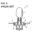
- a bulb socket is, for example, disclosed in Japanese Unexamined Utility Model Publication No. 4-51784.
- a bulb socket B is such that a ring-shaped sealing member 3 is fitted on the outer side surface of a socket main body 2 accommodating a bulb 1.
- the sealing member 3 is squeezed to undergo a resilient deformation between a flange portion 2a of the socket main body 2 and an edge of a mount hole 5 formed in the panel 4 for the bulb socket B.
- the sealing member 3 is held in pressing contact with the flange portion 2a and the edge of the mount hole 5, thereby providing sealing between the edge of the mount hole 5 and the socket main body 2.
- the entire bulb socket B is circumferentially turned while the sealing member 3 is pressed against the panel 4 by the flange portion 2a, whereby the bulb socket B is prevented from coming out by the engagement of the locking pieces 2b with the edge of the mount hole 5 from inside.
- the bulb socket B may be detached from the panel 4, for example, in order to exchange the bulb 1.
- the sealing member 3 since the sealing member 3 is strongly held in pressing contact with the edge of the mount hole 5 when the bulb socket B is mounted, there is a possibility that the sealing member 3 remains held in pressing contact with the edge of the mount hole 5 and, as a result, the sealing member 3 comes off the socket main body 2 as the bulb socket B is detached.
- the sealing member 3 held between the flange portion 2a and the edge of the mount hole 5 is excessively squeezed. If the bulb socket B is circumferentially turned in this state, a sliding resistance between the sealing member 3 and the flange portion 2a and the one between the sealing member 3 and the mount hole 5 increases, and a shear force acts on the sealing member 3 in circumferential direction. As a result, the sealing member 3 is mounted while being improperly deformed and cannot provide a secure sealing.
- the present invention was developed in view of the above problem and an object thereof is to prevent a reduction in sealing function of a sealing member.
- a bulb socket comprising:
- the sealing member is strongly pushed against the edge of the mount hole during the mounting of the bulb socket, the restricting projection comes into contact with the outer side of the edge of the mount hole before the sealing member undergoes an excessive resilient deformation.
- the bulb socket cannot be pushed any deeper.
- the sealing member is not improperly deformed even if the bulb socket is turned in this state and, therefore, can securely display its sealing function.
- the socket main body can be circumferentially turned to engage the locking portion with an edge or edge portion of the mount hole from inside, thereby being mounted so as not to come out during the mounting into the bulb casing.
- the bulb socket further comprises a flange portion formed on the outer circumferential surface of the socket main body for restricting a backward loose movement of the sealing member by being brought or bringable substantially into contact with the sealing member, wherein the sealing is provided between the mount hole and the socket main body by squeezing the sealing member between the flange portion and a sealing surface of the edge of the mount hole to resiliently deform the sealing member in a mounted state of the bulb socket.
- a bulb socket comprising:
- a bulb socket which can prevent a sealing member from coming off the bulb socket during the detachment thereof and can prevent a reduction in sealing function due to the excessively squeezed sealing member during the mounting of the bulb socket.
- the restricting projection on the outer circumferential surface of the socket main body comes into contact with the sealing member to separate it from the edge of the mount hole as the bulb socket is detached.
- an undesirable event where the sealing member comes off the socket main body as the bulb socket is detached can be avoided.
- the sealing member is strongly pushed against the edge of the mount hole by the flange portion during the mounting of the bulb socket, the restricting projection comes into contact with the outer side of the edge of the mount hole before the sealing member undergoes an excessive resilient deformation.
- the bulb socket cannot be pushed any deeper.
- the sealing member is not improperly deformed even if the bulb socket is turned in this state and, therefore, can securely display its sealing function.
- the restricting projection is substantially continuously formed over the entire circumferential surface of the socket main body.
- the restricting projection is continuously formed over the entire circumference of the socket main body, strength against a pushing force from the edge of the mount hole when the bulb socket is pushed is higher as compared to a bulb socket on which a plurality of restricting projections are provided while being spaced apart in the circumferential direction of the socket main body.
- “breakage” and “bending” of the restricting projection can be avoided.
- the restricting projection uniformly comes into contact with the edge of the mount hole over the entire circumference, the oblique mounting of the socket main body into the mount hole can be avoided.
- the restricting projection is formed with a contact surface to be held substantially in pressing contact with the sealing member preferably when the sealing member is resiliently squeezed between the flange portion and the sealing surface to provide sealing.
- the sealing member is or can be held in pressing contact not only with the edge of the mount hole and the flange portion of the socket main body, but also with the contact surface of the restricting projection in a sealed state.
- more secure sealing can be provided between the mount hole and the socket main body.
- the restricting projection is formed with a slanted surface substantially extending along the outer circumferential surface of the sealing member.
- the sealing member comes into contact with a wide area, i.e. the substantially entire slanted surface when being pressed against the restricting projection.
- a possibility of locally recessing the sealing member can be avoided.
- a groove is formed in the outer circumferential surface of the socket main body for at least partly accommodating the sealing member therein.
- the restricting projection comprises one or more push-restricting surfaces for coming into contact with one or more corresponding contact surfaces of the bulb casing, wherein the push-restricting surfaces project at an angle different from 0° or 180°, preferably substantially normal to an outer surface of the socket main body and are arranged preferably circumferentially spaced thereon or thereat.
- a method for mounting a bulb socket in particular according to the invention or an embodiment thereof, comprising:
- the sealing member is strongly pushed against the edge of the mount hole during the mounting of the bulb socket, the restricting projection comes into contact with the outer side of the edge of the mount hole before the sealing member undergoes an excessive resilient deformation.
- the bulb socket cannot be pushed any deeper.
- the sealing member is not improperly deformed even if the bulb socket is turned in this state and, therefore, can securely display its sealing function.
- the socket main body is circumferentially turned to engage the locking portion with an edge of the mount hole from inside, thereby being mounted so as not to come out during the mounting into the bulb casing.
- a flange portion is formed on the outer circumferential surface of the socket main body for restricting a backward loose movement of the sealing member by being bringable into contact with the sealing member, wherein the sealing is provided between the mount hole and the socket main body by squeezing the sealing member between the flange portion and a sealing surface of the edge of the mount hole to resiliently deform the sealing member in a mounted state of the bulb socket.
- the insertion of the socket main body into the bulb casing is restricted by the interaction of one or more push-restricting surfaces provided on the socket main body which come into contact with one or more corresponding contact surfaces of or at the bulb casing, wherein the push-restricting surfaces project at an angle different from 0° or 180°, preferably substantially normal to an outer surface of the socket main body and are arranged preferably circumferentially spaced thereon.
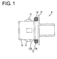
- FIG. 1 is a side view of a socket main body
- FIG. 2 is a section of a bulb casing and a bulb socket
- FIG. 3 is a section of the bulb casing and the bulb socket in a mounted state
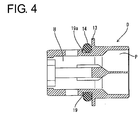
- FIG. 4 is a section showing a modification of the socket main body
- FIG. 5 is a section of a prior art bulb socket.
- a bulb socket S of this embodiment is preferably used for a vehicle light, and is at least partly mountable into a bulb casing C in an inserting direction ID, e.g. from behind.
- a rear end portion of the bulb casing C where the bulb socket S is to be mounted is formed into a hollow cylindrical portion 17, and a mount hole 11 having a diameter slightly larger than the outer diameter of the bulb socket S is formed by providing a substantially concentric annular projection 10 on the inner circumferential surface of the cylindrical portion 17 at a position slightly distanced from the rear opening edge.
- the bulb socket S is mounted by being at least partly inserted into this mount hole 11.
- the annular projection 10 is formed with one or more escaping portions 10a corresponding to one or more locking claws 12 as locking portions for a socket main body D to be described later preferably by cutting, and the locking claws 12 are or can be at least partly introduced through the escaping portions 10a during the insertion of the bulb socket S in the inserting direction ID into the mount hole 11.
- the rear surface of the annular projection 10 serves as a contact surface 16b with which a restricting projection 15 of the socket main body D to be described later comes substantially into contact, and the front surface thereof (as seen in the inserting direction ID) serves as a locking surface 16c for preventing the bulb socket S from coming out by being brought into contact with the rear end of the locking claws 12.
- the inner circumferential surface of a portion of the cylindrical portion 17 projecting backward from the contact surface 16b serves as a sealing surface 16a.
- This sealing surface 16a is so slanted as to widen toward the back or outwardly and is to be held substantially in pressing contact with an O-ring 14 when the bulb socket S is mounted into the bulb casing C.
- An edge or edge portion 16 of the mount hole 11 (hereinafter, merely edge 16) is formed by the sealing surface 16a, the contact surface 16b and the locking surface 16c.
- the bulb socket S is comprised of the socket main body D made e.g. of a synthetic resin material, a pair of terminal fittings R mounted in the socket main body D, and a bulb B connected or connectable with these terminal fittings R.
- the socket main body D preferably has a hollow cylindrical shape as a whole, and the front side of the inside thereof serves as an at least partly accommodating portion H for accommodating the terminal fittings R and a base portion of the bulb B.
- the bulb B is connected with the terminal fittings R by being inserted into the socket main body D through a front opening.
- the rear side of the inside of the socket main body D preferably serves as a sealing portion P for individually accommodating portions of the terminal fittings R crimped or bent or folded into connection with wires E, and the sealing portion P is or can be held watertight by rubber plugs 20 mounted or mountable on the wires E.
- connection with the wires E such as insulation displacement or soldering can be also used.
- a flange portion 13 is formed on an outer circumferential surface 18 of the socket main body D.
- This flange portion 13 is a jaw portion which extends to substantially cover the contact surface 16b and the sealing surface 16a of the edge 16 from a direction opposed to the inserting direction ID or from behind the bulb casing C with the bulb socket S mounted in the bulb casing C.
- the flange portion 13 radially projects by a radial distance greater than that of the contact surface 16b and/or the sealing surface 16a.
- the O-ring 14 as a sealing member is mounted or mountable on the outer circumferential surface 18 of the socket main body D near and before the flange portion 13, and this O-ring 14 is prevented from loosely moving backward by the flange portion 13.
- the restricting projection 15 preferably continuous over the substantially entire circumference is formed on the outer circumferential surface 18 of the socket main body D.
- the ring-shaped restricting projection 15 has an outer diameter larger than an inner diameter of the mount hole 11 and is provided before the O-ring 14. By taking such a form, the restricting projection 15 can prevent the O-ring 14 from loosely moving in the inserting direction ID or forward. In other words, the O-ring 14 is prevented from loosely moving along the longitudinal direction by the flange portion 13 and the restricting projection 15.
- the rear surface of the restricting projection 15 facing the O-ring 14 is formed into a slanted surface 15a extending substantially along the outer surface of the O-ring 14.
- the slanted surface 15a and part of the front surface of the O-ring 14 substantially face each other at such a short distance that there is almost no clearance therebetween.
- the front surface of the restricting projection 15 opposite from the slanted surface 15a is formed into a push-restricting surface 15b which preferably is substantially normal to the outer circumferential surface of the socket main body D.
- the push-restricting surface 15b can be brought substantially into contact with the contact surface 16b from behind during the insertion of the bulb socket S, and this contact can prevent the bulb sokket S from being pushed in the inserting direction ID into the mount hole 11 deeper than necessary or more than a specified (predetermined or predeterminable) amount.
- One or more, e.g. two locking claws 12 substantially corresponding to the one or more escaping portions 10a are formed before the restricting projection 15 while being spaced apart from the push-restricting surface 15b by a distance slightly longer than the thickness of the annular projection 10 and circumferentially spaced apart from each other e.g. by 180°.
- These locking claws 12 can be introduced through the escaping portions 10a during the insertion of the bulb socket S into the mount hole 11 of the bulb casing C.
- the rear ends of the locking claws 12 stand in a direction at an angle different from 0° or 180°, preferably substantially normal to the outer circumferential surface of the socket main body D so as to be brought into contact with the locking surface 16c of the edge 16 from inside for locking.
- the bulb socket S having the O-ring 14 mounted thereon is at least partly inserted in the inserting direction ID into the mount hole 11 of the bulb casing C with the bulb B faced forward.
- the locking claws 12 are substantially aligned with and introduced through the escaping projections 10a during this insertion, the O-ring 14 comes into contact with the sealing surface 16a of the edge 16.
- the O-ring 14 is resiliently deformed by being squeezed between the sealing surface 16a, the front surface of the flange portion 13, the outer circumferential surface 18 of the socket main body D and the slanted surface 15a of the restricting projection 15 and are held in pressing contact with the respective surfaces.
- the sealing surface 16a held in pressing contact pushes the O-ring 14 in an oblique radially inward direction to the back from a radially outward position, whereas the slanted surface 15a of the restricting projection 15 pushes the O-ring 14 in an oblique outward direction to the back from a radially inward position.
- the front surface of the flange portion 13 pushes the O-ring 14 in the inserting direction ID or forward
- the outer circumferential surface 18 of the socket main body D pushes the O-ring 14 in a radially outward direction which is at an angle different from 0° or 180°, preferably substantially normal to the inserting direction ID of the bulb socket S.
- the bulb socket S With the O-ring 14 pushed by the respective surfaces, the bulb socket S is circumferentially turned to a position where the locking claws 12 are not aligned with the escaping portions 10a, i.e. the rear ends of the lokking claws 12 face the locking surface 16c of the edge 16 (so called bayonet coupling). Then, the bulb socket S is pushed backward or in a direction opposed to the inserting direction ID with respect to the bulb casing C by the resiliency of the squeezed O-ring 14, and the locking claws 12 are engaged with the locking surface 16c of the edge 16, thereby holding the bulb socket S so as not to come out.
- the bulb socket S mounted into the bulb casing C is or can be detached by circumferentially or azimuthally turning the bulb socket S to substantially align the locking claws 12 with the escaping portions 10a and then being pulled out or in a direction opposed to the inserting direction ID. Even if the front surface of the O-ring 14 is held in pressing contact with the sealing surface 16a of the edge 16 during the detachment, the slanted surface 15a of the restricting projection 15 comes into contact with the O-ring 14 from front as the bulb socket S is detached, thereby separating the O-ring 14 from the sealing surface 16a. Thus, the O-ring 14 moves backward together with the socket main body D. Therefore, the O-ring 14 remains mounted on the bulb socket S when the bulb socket S is detached.
- the O-ring 14 can securely display its sealing functions by being prevented from excessive squeezing during the mounting of the bulb socket S. Further, the O-ring 14 can be prevented from coming off the bulb socket S during the detachment of the bulb socket S.
- the restricting projection 15 is continuously formed over the substantially entire circumference of the socket main body D, strength against a backward-acting pushing force from the contact surface 16b of the mount hole 11 when the bulb sokket S is pushed into the mount hole 11 is higher as compared to a bulb socket on which a plurality of restricting projections are provided while being spaced apart in the circumferential direction of the socket main body D. Thus, breakage and bending of the restricting projection 15 can be avoided. Further, since the push-restricting surface 15b of the restricting projection 15 uniformly comes into contact with the contact surface 16b over the substantially entire circumference, the oblique mounting of the socket main body D into the mount hole 11 can be avoided.
- the O-ring 14 When sealing is provided between the mount hole 11 and the socket main body D, the O-ring 14 is held in pressing contact not only with the front surface of the flange portion 13, the sealing surface 16a of the edge 16 and the outer circumferential surface 18 of the socket main body D, but also with the slanted surface 15a of the restricting projection 15. Thus, a sealing area is increased to provide more secure sealing.
- a restricting projection 15 is preferably substantially continuously formed on an outer circumferential surface 18 of a socket main body D over the entire circumference before an O-ring 14 fitted on the socket main body D.
- the restricting projection 15 can come substantially into contact with the O-ring 14 during the detachment of a bulb socket S, thereby separating the O-ring 14 from a sealing surface 16a of an edge 16 of a mount hole 11.
- the restricting projection 15 comes or can come into contact with a contact surface 16b of the edge 16 during the mounting of the bulb socket S, thereby preventing the bulb socket S from being pushed any further in the inserting direction ID. This prevents the excessive squeezing of the O-ring 14, which leads to a reduction in its sealing function.
- FIG. 4 shows a modification of the means for preventing the O-ring 14 from coming off.
- This modification is such that a groove 19 in which the O-ring 14 is fittable is formed over the entire circumference of the socket main body D, and the O-ring 14 having an inner diameter smaller than the outer diameter of the socket main body D is or can be at least partly fitted or inserted in this groove 19.
- a front surface 19a of the groove 19 can come into contact with the O-ring 14 to separate it from the sealing surface 16a of the edge 16, displaying the same effect as in the first embodiment.
Landscapes
- Fastening Of Light Sources Or Lamp Holders (AREA)
- Arrangement Of Elements, Cooling, Sealing, Or The Like Of Lighting Devices (AREA)
- Connecting Device With Holders (AREA)
- Connector Housings Or Holding Contact Members (AREA)
Abstract
Description
- The present invention relates to a bulb socket having a watertight structure and to a method for mounting or assembling it.
- A bulb socket is, for example, disclosed in Japanese Unexamined Utility Model Publication No. 4-51784. As shown in FIG. 5, a bulb socket B is such that a ring-
shaped sealing member 3 is fitted on the outer side surface of a socketmain body 2 accommodating a bulb 1. When the bulb socket B is mounted on apanel 4, the sealingmember 3 is squeezed to undergo a resilient deformation between aflange portion 2a of the socketmain body 2 and an edge of amount hole 5 formed in thepanel 4 for the bulb socket B. Thus, the sealingmember 3 is held in pressing contact with theflange portion 2a and the edge of themount hole 5, thereby providing sealing between the edge of themount hole 5 and the socketmain body 2. Upon mounting the bulb socket B, after lockingpieces 2b provided on the outer circumferential surface of the socketmain body 2 are introduced through escapingportions 5a formed at the edge of themount hole 5, the entire bulb socket B is circumferentially turned while the sealingmember 3 is pressed against thepanel 4 by theflange portion 2a, whereby the bulb socket B is prevented from coming out by the engagement of thelocking pieces 2b with the edge of themount hole 5 from inside. - The bulb socket B may be detached from the
panel 4, for example, in order to exchange the bulb 1. However, since the sealingmember 3 is strongly held in pressing contact with the edge of themount hole 5 when the bulb socket B is mounted, there is a possibility that the sealingmember 3 remains held in pressing contact with the edge of themount hole 5 and, as a result, the sealingmember 3 comes off the socketmain body 2 as the bulb socket B is detached. - Further, if the
flange portion 2a of the socketmain body 2 is pressed against the edge of themount hole 5 more than necessary during the mounting of the bulb socket B, the sealingmember 3 held between theflange portion 2a and the edge of themount hole 5 is excessively squeezed. If the bulb socket B is circumferentially turned in this state, a sliding resistance between the sealingmember 3 and theflange portion 2a and the one between the sealingmember 3 and themount hole 5 increases, and a shear force acts on the sealingmember 3 in circumferential direction. As a result, the sealingmember 3 is mounted while being improperly deformed and cannot provide a secure sealing. - The present invention was developed in view of the above problem and an object thereof is to prevent a reduction in sealing function of a sealing member.
- This object is solved according to the invention by a bulb socket according to claim 1 and by a method according to claim 9. Preferred embodiments of the invention are subject of the dependent claims.
- According to the invention, there is provided a bulb socket, comprising:
- a socket main body in which a bulb can be mounted,
- a sealing member fittable or fitted on the outer circumferential surface of the socket main body,
- at least one locking portion formed on the outer circumferential surface of the socket main body,
- the socket main body being at least partly insertable into a mount hole of a bulb casing and locked thereto by the locking portion, and sealing being provided between the mount hole and the socket main body by the sealing member, and
- a restricting projection formed on or at the outer circumferential surface of the socket main body at a position before the sealing member (or between the sealing member and the mount hole) with respect to an inserting direction of the socket main body into the mount hole for coming into contact with the edge of the mount hole from outside.
-
- Accordingly, even if the sealing member is strongly pushed against the edge of the mount hole during the mounting of the bulb socket, the restricting projection comes into contact with the outer side of the edge of the mount hole before the sealing member undergoes an excessive resilient deformation. Thus, the bulb socket cannot be pushed any deeper. The sealing member is not improperly deformed even if the bulb socket is turned in this state and, therefore, can securely display its sealing function.
- According to a preferred embodiment of the invention, the socket main body can be circumferentially turned to engage the locking portion with an edge or edge portion of the mount hole from inside, thereby being mounted so as not to come out during the mounting into the bulb casing.
- Preferably, the bulb socket further comprises a flange portion formed on the outer circumferential surface of the socket main body for restricting a backward loose movement of the sealing member by being brought or bringable substantially into contact with the sealing member,
wherein the sealing is provided between the mount hole and the socket main body by squeezing the sealing member between the flange portion and a sealing surface of the edge of the mount hole to resiliently deform the sealing member in a mounted state of the bulb socket. - According to a further preferred embodiment of the invention, there is provided a bulb socket, comprising:
- a socket main body in which a bulb is mounted or mountable,
- a ring-shaped sealing member fitted on the outer circumferential surface of the socket main body,
- a flange portion formed on the outer circumferential surface of the socket main body for restricting a backward loose movement of the sealing member by being brought or bringable substantially into contact with the sealing member,
- a locking portion formed on the outer circumferential surface of the socket main body,
- the socket main body being at least partly inserted or insertable into a mount hole of a bulb casing and circumferentially turned to engage the locking portion with an edge of the mount hole from inside, thereby being mounted so as not to come out during the mounting into the bulb casing, and sealing being provided between the mount hole and the socket main body by squeezing the sealing member substantially between the flange portion and a sealing surface of the edge of the mount hole to resiliently deform the sealing member in a mounted state of the bulb socket, and
- a restricting projection formed on or at the outer circumferential surface of the socket main body at a position before the sealing member with respect to an inserting direction of the socket main body into the mount hole for coming into contact with the edge of the mount hole from outside.
-
- Accordingly, there is provides a bulb socket which can prevent a sealing member from coming off the bulb socket during the detachment thereof and can prevent a reduction in sealing function due to the excessively squeezed sealing member during the mounting of the bulb socket.
- Particularly, even if the sealing member is held in pressing contact with the outer side of the edge of the mount hole during the detachment of the bulb socket, the restricting projection on the outer circumferential surface of the socket main body comes into contact with the sealing member to separate it from the edge of the mount hole as the bulb socket is detached. Thus, an undesirable event where the sealing member comes off the socket main body as the bulb socket is detached can be avoided.
- Further, even if the sealing member is strongly pushed against the edge of the mount hole by the flange portion during the mounting of the bulb socket, the restricting projection comes into contact with the outer side of the edge of the mount hole before the sealing member undergoes an excessive resilient deformation. Thus, the bulb socket cannot be pushed any deeper. The sealing member is not improperly deformed even if the bulb socket is turned in this state and, therefore, can securely display its sealing function.
- Preferably, the restricting projection is substantially continuously formed over the entire circumferential surface of the socket main body.
- Accordingly, since the restricting projection is continuously formed over the entire circumference of the socket main body, strength against a pushing force from the edge of the mount hole when the bulb socket is pushed is higher as compared to a bulb socket on which a plurality of restricting projections are provided while being spaced apart in the circumferential direction of the socket main body. Thus, "breakage" and "bending" of the restricting projection can be avoided. Further, since the restricting projection uniformly comes into contact with the edge of the mount hole over the entire circumference, the oblique mounting of the socket main body into the mount hole can be avoided.
- Further preferably, the restricting projection is formed with a contact surface to be held substantially in pressing contact with the sealing member preferably when the sealing member is resiliently squeezed between the flange portion and the sealing surface to provide sealing.
- Accordingly, the sealing member is or can be held in pressing contact not only with the edge of the mount hole and the flange portion of the socket main body, but also with the contact surface of the restricting projection in a sealed state. Thus, more secure sealing can be provided between the mount hole and the socket main body.
- Still further preferably, the restricting projection is formed with a slanted surface substantially extending along the outer circumferential surface of the sealing member.
- Accordingly, since a contact portion of the restricting projection with the sealing member is formed into the slanted surface substantially extending along the outer circumferential surface of the sealing member, the sealing member comes into contact with a wide area, i.e. the substantially entire slanted surface when being pressed against the restricting projection. Thus, a possibility of locally recessing the sealing member can be avoided.
- Further preferably, a groove is formed in the outer circumferential surface of the socket main body for at least partly accommodating the sealing member therein.
- Most preferably, the restricting projection comprises one or more push-restricting surfaces for coming into contact with one or more corresponding contact surfaces of the bulb casing, wherein the push-restricting surfaces project at an angle different from 0° or 180°, preferably substantially normal to an outer surface of the socket main body and are arranged preferably circumferentially spaced thereon or thereat.
- According to the invention, there is further provided a method for mounting a bulb socket, in particular according to the invention or an embodiment thereof, comprising:
- providing a socket main body in which a bulb can be mounted,
- fitting a sealing member on the outer circumferential surface of the socket main body,
- at least partly inserting the socket main body into a mount hole of a bulb casing and locked thereto by the locking portion formed on the outer circumferential surface of the socket main body, and
- providing sealing between the mount hole and the socket main body by the sealing member, and wherein an insertion of the socket main body into the bulb casing is restricted by a restricting projection formed on or at the outer circumferential surface of the socket main body at a position before the sealing member with respect to an inserting direction of the socket main body into the mount hole coming into contact with the edge of the mount hole from outside.
-
- Accordingly, even if the sealing member is strongly pushed against the edge of the mount hole during the mounting of the bulb socket, the restricting projection comes into contact with the outer side of the edge of the mount hole before the sealing member undergoes an excessive resilient deformation. Thus, the bulb socket cannot be pushed any deeper. The sealing member is not improperly deformed even if the bulb socket is turned in this state and, therefore, can securely display its sealing function.
- According to a preferred embodiment of the invention, the socket main body is circumferentially turned to engage the locking portion with an edge of the mount hole from inside, thereby being mounted so as not to come out during the mounting into the bulb casing.
- Preferably, a flange portion is formed on the outer circumferential surface of the socket main body for restricting a backward loose movement of the sealing member by being bringable into contact with the sealing member,
wherein the sealing is provided between the mount hole and the socket main body by squeezing the sealing member between the flange portion and a sealing surface of the edge of the mount hole to resiliently deform the sealing member in a mounted state of the bulb socket. - Most preferably, the insertion of the socket main body into the bulb casing is restricted by the interaction of one or more push-restricting surfaces provided on the socket main body which come into contact with one or more corresponding contact surfaces of or at the bulb casing, wherein the push-restricting surfaces project at an angle different from 0° or 180°, preferably substantially normal to an outer surface of the socket main body and are arranged preferably circumferentially spaced thereon.
- These and other objects, features and advantages of the present invention will become more apparent upon reading of the following detailed description of preferred embodiments and accompanying drawings. It should be understood that even though embodiments are separately described, single features thereof may be combined to additional embodiments.
FIG. 1 is a side view of a socket main body,
FIG. 2 is a section of a bulb casing and a bulb socket,
FIG. 3 is a section of the bulb casing and the bulb socket in a mounted state,
FIG. 4 is a section showing a modification of the socket main body, and
FIG. 5 is a section of a prior art bulb socket. - Hereinafter, preferred embodiments of the present invention are described with reference to the accompanying drawings. It should be noted that a side in the inserting direction ID of a bulb socket S into a bulb casing C (left side in FIGS. 1 to 4) is referred to as front side in the description below.
- A bulb socket S of this embodiment is preferably used for a vehicle light, and is at least partly mountable into a bulb casing C in an inserting direction ID, e.g. from behind. A rear end portion of the bulb casing C where the bulb socket S is to be mounted is formed into a hollow
cylindrical portion 17, and amount hole 11 having a diameter slightly larger than the outer diameter of the bulb socket S is formed by providing a substantially concentricannular projection 10 on the inner circumferential surface of thecylindrical portion 17 at a position slightly distanced from the rear opening edge. The bulb socket S is mounted by being at least partly inserted into thismount hole 11. Theannular projection 10 is formed with one or more escapingportions 10a corresponding to one ormore locking claws 12 as locking portions for a socket main body D to be described later preferably by cutting, and the lockingclaws 12 are or can be at least partly introduced through the escapingportions 10a during the insertion of the bulb socket S in the inserting direction ID into themount hole 11. - The rear surface of the
annular projection 10 serves as acontact surface 16b with which a restrictingprojection 15 of the socket main body D to be described later comes substantially into contact, and the front surface thereof (as seen in the inserting direction ID) serves as a lockingsurface 16c for preventing the bulb socket S from coming out by being brought into contact with the rear end of the lockingclaws 12. Further, the inner circumferential surface of a portion of thecylindrical portion 17 projecting backward from thecontact surface 16b serves as a sealingsurface 16a. This sealingsurface 16a is so slanted as to widen toward the back or outwardly and is to be held substantially in pressing contact with an O-ring 14 when the bulb socket S is mounted into the bulb casing C. An edge oredge portion 16 of the mount hole 11 (hereinafter, merely edge 16) is formed by the sealingsurface 16a, thecontact surface 16b and the lockingsurface 16c. - Next, the bulb socket S is described. The bulb socket S is comprised of the socket main body D made e.g. of a synthetic resin material, a pair of terminal fittings R mounted in the socket main body D, and a bulb B connected or connectable with these terminal fittings R. The socket main body D preferably has a hollow cylindrical shape as a whole, and the front side of the inside thereof serves as an at least partly accommodating portion H for accommodating the terminal fittings R and a base portion of the bulb B. The bulb B is connected with the terminal fittings R by being inserted into the socket main body D through a front opening. On the other hand, the rear side of the inside of the socket main body D preferably serves as a sealing portion P for individually accommodating portions of the terminal fittings R crimped or bent or folded into connection with wires E, and the sealing portion P is or can be held watertight by rubber plugs 20 mounted or mountable on the wires E. However, other possibilities for connection with the wires E such as insulation displacement or soldering can be also used.
- A
flange portion 13 is formed on an outercircumferential surface 18 of the socket main body D. Thisflange portion 13 is a jaw portion which extends to substantially cover thecontact surface 16b and the sealingsurface 16a of theedge 16 from a direction opposed to the inserting direction ID or from behind the bulb casing C with the bulb socket S mounted in the bulb casing C. In other words, theflange portion 13 radially projects by a radial distance greater than that of thecontact surface 16b and/or the sealingsurface 16a. - The O-
ring 14 as a sealing member is mounted or mountable on the outercircumferential surface 18 of the socket main body D near and before theflange portion 13, and this O-ring 14 is prevented from loosely moving backward by theflange portion 13. The restrictingprojection 15 preferably continuous over the substantially entire circumference is formed on the outercircumferential surface 18 of the socket main body D. The ring-shaped restrictingprojection 15 has an outer diameter larger than an inner diameter of themount hole 11 and is provided before the O-ring 14. By taking such a form, the restrictingprojection 15 can prevent the O-ring 14 from loosely moving in the inserting direction ID or forward. In other words, the O-ring 14 is prevented from loosely moving along the longitudinal direction by theflange portion 13 and the restrictingprojection 15. The rear surface of the restrictingprojection 15 facing the O-ring 14 is formed into aslanted surface 15a extending substantially along the outer surface of the O-ring 14. When the O-ring 14 is mounted at such a position on the socket main body D that the rear surface thereof is in contact with the front surface of theflange portion 13, theslanted surface 15a and part of the front surface of the O-ring 14 substantially face each other at such a short distance that there is almost no clearance therebetween. The front surface of the restrictingprojection 15 opposite from the slantedsurface 15a is formed into a push-restrictingsurface 15b which preferably is substantially normal to the outer circumferential surface of the socket main body D. Since there is only a small clearance between the inner circumferential surface of themount hole 11 and the outer circumferential surface of the socket main body D as mentioned above, the push-restrictingsurface 15b can be brought substantially into contact with thecontact surface 16b from behind during the insertion of the bulb socket S, and this contact can prevent the bulb sokket S from being pushed in the inserting direction ID into themount hole 11 deeper than necessary or more than a specified (predetermined or predeterminable) amount.. - One or more, e.g. two locking
claws 12 substantially corresponding to the one or more escapingportions 10a are formed before the restrictingprojection 15 while being spaced apart from the push-restrictingsurface 15b by a distance slightly longer than the thickness of theannular projection 10 and circumferentially spaced apart from each other e.g. by 180°. These lockingclaws 12 can be introduced through the escapingportions 10a during the insertion of the bulb socket S into themount hole 11 of the bulb casing C. The rear ends of the lockingclaws 12 stand in a direction at an angle different from 0° or 180°, preferably substantially normal to the outer circumferential surface of the socket main body D so as to be brought into contact with the lockingsurface 16c of theedge 16 from inside for locking. - Next, the functions of this embodiment thus constructed is described.
- First, the bulb socket S having the O-
ring 14 mounted thereon is at least partly inserted in the inserting direction ID into themount hole 11 of the bulb casing C with the bulb B faced forward. When the lockingclaws 12 are substantially aligned with and introduced through the escapingprojections 10a during this insertion, the O-ring 14 comes into contact with the sealingsurface 16a of theedge 16. When the bulb socket S is further pushed from this position, the O-ring 14 is resiliently deformed by being squeezed between the sealingsurface 16a, the front surface of theflange portion 13, the outercircumferential surface 18 of the socket main body D and theslanted surface 15a of the restrictingprojection 15 and are held in pressing contact with the respective surfaces. The sealingsurface 16a held in pressing contact pushes the O-ring 14 in an oblique radially inward direction to the back from a radially outward position, whereas the slantedsurface 15a of the restrictingprojection 15 pushes the O-ring 14 in an oblique outward direction to the back from a radially inward position. Further, the front surface of theflange portion 13 pushes the O-ring 14 in the inserting direction ID or forward, and the outercircumferential surface 18 of the socket main body D pushes the O-ring 14 in a radially outward direction which is at an angle different from 0° or 180°, preferably substantially normal to the inserting direction ID of the bulb socket S. With the O-ring 14 pushed by the respective surfaces, the bulb socket S is circumferentially turned to a position where the lockingclaws 12 are not aligned with the escapingportions 10a, i.e. the rear ends of thelokking claws 12 face the lockingsurface 16c of the edge 16 (so called bayonet coupling). Then, the bulb socket S is pushed backward or in a direction opposed to the inserting direction ID with respect to the bulb casing C by the resiliency of the squeezed O-ring 14, and the lockingclaws 12 are engaged with the lockingsurface 16c of theedge 16, thereby holding the bulb socket S so as not to come out. - Even if an attempt is made to push the bulb socket S into the
mount hole 11 deeper than necessary during the mounting of the bulb socket S into the bulb casing C, the push-restrictingsurface 15b of the restrictingprojection 15 comes into contact with thecontact surface 16b of theedge 16, whereby preventing the bulb socket S from being pushed any further in the inserting direction ID. This prevents the O-ring 14 from being excessively squeezed. Thus, an undesirable event where a sliding resistance between the rear surface of the O-ring 14 and the front surface of theflange portion 13 and a sliding resistance between the front-surface of the O-ring 14 and the sealingsurface 16a become excessive to exert a shear force on the O-ring 14 and, as a result, the O-ring 14 is improperly mounted to reduce sealability can be avoided. - The bulb socket S mounted into the bulb casing C is or can be detached by circumferentially or azimuthally turning the bulb socket S to substantially align the locking
claws 12 with the escapingportions 10a and then being pulled out or in a direction opposed to the inserting direction ID. Even if the front surface of the O-ring 14 is held in pressing contact with the sealingsurface 16a of theedge 16 during the detachment, theslanted surface 15a of the restrictingprojection 15 comes into contact with the O-ring 14 from front as the bulb socket S is detached, thereby separating the O-ring 14 from the sealingsurface 16a. Thus, the O-ring 14 moves backward together with the socket main body D. Therefore, the O-ring 14 remains mounted on the bulb socket S when the bulb socket S is detached. - As described above, according to this embodiment, the O-
ring 14 can securely display its sealing functions by being prevented from excessive squeezing during the mounting of the bulb socket S. Further, the O-ring 14 can be prevented from coming off the bulb socket S during the detachment of the bulb socket S. - Since the restricting
projection 15 is continuously formed over the substantially entire circumference of the socket main body D, strength against a backward-acting pushing force from thecontact surface 16b of themount hole 11 when the bulb sokket S is pushed into themount hole 11 is higher as compared to a bulb socket on which a plurality of restricting projections are provided while being spaced apart in the circumferential direction of the socket main body D. Thus, breakage and bending of the restrictingprojection 15 can be avoided. Further, since the push-restrictingsurface 15b of the restrictingprojection 15 uniformly comes into contact with thecontact surface 16b over the substantially entire circumference, the oblique mounting of the socket main body D into themount hole 11 can be avoided. - When sealing is provided between the
mount hole 11 and the socket main body D, the O-ring 14 is held in pressing contact not only with the front surface of theflange portion 13, the sealingsurface 16a of theedge 16 and the outercircumferential surface 18 of the socket main body D, but also with theslanted surface 15a of the restrictingprojection 15. Thus, a sealing area is increased to provide more secure sealing. - Even if the O-
ring 14 is pushed by the restrictingprojection 15, there is no possibility of locally recessing the O-ring 14 since the contact portion of the restrictingprojection 15 with the O-ring 14 is the slantedsurface 15a extending along the outer surface of the O-ring. - Accordingly, to provide a bulb socket which can prevent a sealing member from coming off a socket main body during the detachment of the bulb socket and cause the sealing member to securely display its function in a mounted state, a restricting
projection 15 is preferably substantially continuously formed on an outercircumferential surface 18 of a socket main body D over the entire circumference before an O-ring 14 fitted on the socket main body D. Thus, the restrictingprojection 15 can come substantially into contact with the O-ring 14 during the detachment of a bulb socket S, thereby separating the O-ring 14 from a sealingsurface 16a of anedge 16 of amount hole 11. Further, the restrictingprojection 15 comes or can come into contact with acontact surface 16b of theedge 16 during the mounting of the bulb socket S, thereby preventing the bulb socket S from being pushed any further in the inserting direction ID. This prevents the excessive squeezing of the O-ring 14, which leads to a reduction in its sealing function. - FIG. 4 shows a modification of the means for preventing the O-
ring 14 from coming off. - This modification is such that a
groove 19 in which the O-ring 14 is fittable is formed over the entire circumference of the socket main body D, and the O-ring 14 having an inner diameter smaller than the outer diameter of the socket main body D is or can be at least partly fitted or inserted in thisgroove 19. Thus, even if the 0-ring 14 is held in pressing contact with the sealingsurface 16a of theedge 16 during the detachment of the bulb socket S, afront surface 19a of thegroove 19 can come into contact with the O-ring 14 to separate it from the sealingsurface 16a of theedge 16, displaying the same effect as in the first embodiment. - The present invention is not limited to the above described and illustrated embodiments. For example, the following embodiments are also embraced by the technical scope of the present invention as defined by the claims. Beside the following embodiments, various changes can be made without departing from the scope and spirit of the present invention as defined by the claims.
- (1) The slanted
surface 15a of the restrictingprojection 15 may be an arcuate surface extending along the outer circumferential surface of the O-ring 14. - (2) Although the sealing
surface 16a of theedge 16 of themount hole 11 is slanted in the foregoing embodiment, it may be a surface extending normal to the mounting and detaching directions of the bulb socket S into and from themount hole 11. - (3) When sealing is provided between the
mount hole 11 and the bulb sokket D, the O-ring 14 may not be in contact with theslanted surface 15a of the restrictingprojection 15. - (4) A plurality of restricting projections may be provided while being spaced apart in the circumferential direction of the socket main body D.
- (5) Even though the bulb socket S has been described to be locked into
the socket main body D by means of inserting the locking
portions 12 into theescape grooves 10a and circumferentially or azimuthally turning the bulb socket S and sokket main body D with respect to each other (bayonet coupling), other ways of locking are possible such as by means of locking portions being resiliently deflectable and engaging corresponding mating locking portions can be used according to the invention. -
-
- B ...
- bulb
- C ...
- bulb casing
- D ...
- socket main body
- S ...
- bulb socket
- 11 ...
- mount hole
- 12 ...
- locking claw (locking portion)
- 13 ...
- flange portion
- 14 ...
- O-ring (sealing member)
- 15 ...
- restricting projection
- 15a ...
- slanted surface (contact surface)
- 16 ...
- edge of the mount hole
- 16a ...
- sealing surface
- 16b ...
- contact surface
- 16c ...
- locking surface
Claims (11)
- A bulb socket (S), comprising:a socket main body (D) in which a bulb (B) can be mounted,a sealing member (14) fittable on the outer circumferential surface (18) of the socket main body (D),at least one locking portion (12) formed on the outer circumferential surface (18) of the socket main body (D),the socket main body (D) being at least partly insertable into a mount hole (11) of a bulb casing (C) and locked thereto by the locking portion (12), and sealing being provided between the mount hole (11) and the socket main body (D) by the sealing member (14), anda restricting projection (15) formed on or at the outer circumferential surface (18) of the socket main body (D) at a position before the sealing member (14) with respect to an inserting direction (ID) of the socket main body (D) into the mount hole (11) for coming into contact with the edge of the mount hole (11) from outside.
- A bulb socket according to claim 1, wherein the socket main body (D) can be circumferentially turned to engage the locking portion (12) with an edge of the mount hole (11) from inside, thereby being mounted so as not to come out during the mounting into the bulb casing (C).
- A bulb socket according to one or more of the preceding claims, further comprising a flange portion (13) formed on the outer circumferential surface (18) of the socket main body (D) for restricting a backward loose movement of the sealing member (14) by being bringable substantially into contact with the sealing member (14),
wherein the sealing is provided between the mount hole (11) and the socket main body (D) by squeezing the sealing member (14) between the flange portion (13) and a sealing surface (16a) of the edge of the mount hole (11) to resiliently deform the sealing member (14) in a mounted state of the bulb socket (S). - A bulb socket according to one or more of the preceding claims, wherein the restricting projection (15) is continuously formed over the entire circumferential surface of the socket main body (D).
- A bulb socket according to one or more of the preceding claims, wherein the restricting projection (15) is formed with a contact surface (15a) to be held in pressing contact with the sealing member (14) preferably when the sealing member (14) is resiliently squeezed between the flange portion (13) and the sealing surface (16a) to provide sealing.
- A bulb socket according to one or more of the preceding claims, wherein the restricting projection (15) is formed with a slanted surface (15a) substantially extending along the outer circumferential surface of the sealing member (14).
- A bulb socket according to one or more of the preceding claims, wherein a groove (19) is formed in the outer circumferential surface (18) of the sokket main body (D) for at least partly accommodating the sealing member (14) therein.
- A bulb socket according to one or more of the preceding claims, wherein the restricting projection (15) comprises one or more push-restricting surfaces (15b) for coming into contact with one or more corresponding contact surfaces (16b) of the bulb casing (C), wherein the push-restricting surfaces (15b) project at an angle different from 0° or 180°, preferably substantially normal to an outer surface of the socket main body (D) and are arranged preferably circumferentially spaced thereon.
- A method for mounting a bulb socket (S), comprising:providing a socket main body (D) in which a bulb (B) can be mounted,fitting a sealing member (14) on the outer circumferential surface (18) of the socket main body (D),at least partly inserting the socket main body (D) into a mount hole (11) of a bulb casing (C) and locked thereto by the locking portion (12) formed on the outer circumferential surface (18) of the socket main body (D), andproviding sealing between the mount hole (11) and the socket main body (D) by the sealing member (14), andwherein an insertion of the socket main body (S) into the bulb casing (C) is restricted by a restricting projection (15) formed on or at the outer circumferential surface (18) of the socket main body (D) at a position before the sealing member (14) with respect to an inserting direction (ID) of the socket main body (D) into the mount hole (11) coming into contact with the edge of the mount hole (11) from outside.
- A method according to claim 9, wherein the socket main body (D) is circumferentially turned to engage the locking portion (12) with an edge of the mount hole (11) from inside, thereby being mounted so as not to come out during the mounting into the bulb casing (C).
- A bulb socket according to claim 9 or 10, wherein
a flange portion (13) is formed on the outer circumferential surface (18) of the socket main body (D) for restricting a backward loose movement of the sealing member (14) by being bringable into contact with the sealing member (14),
the sealing is provided between the mount hole (11) and the socket main body (D) by squeezing the sealing member (14) between the flange portion (13) and a sealing surface (16a) of the edge of the mount hole (11) to resiliently deform the sealing member (14) in a mounted state of the bulb socket (S).
Applications Claiming Priority (2)
| Application Number | Priority Date | Filing Date | Title |
|---|---|---|---|
| JP2001332318A JP3937803B2 (en) | 2001-10-30 | 2001-10-30 | Valve socket |
| JP2001332318 | 2001-10-30 |
Publications (2)
| Publication Number | Publication Date |
|---|---|
| EP1309045A1 true EP1309045A1 (en) | 2003-05-07 |
| EP1309045B1 EP1309045B1 (en) | 2004-08-25 |
Family
ID=19147751
Family Applications (1)
| Application Number | Title | Priority Date | Filing Date |
|---|---|---|---|
| EP02024516A Expired - Lifetime EP1309045B1 (en) | 2001-10-30 | 2002-10-30 | A bulb socket and a method for mounting it |
Country Status (3)
| Country | Link |
|---|---|
| US (1) | US6752518B2 (en) |
| EP (1) | EP1309045B1 (en) |
| JP (1) | JP3937803B2 (en) |
Families Citing this family (3)
| Publication number | Priority date | Publication date | Assignee | Title |
|---|---|---|---|---|
| JP2007059200A (en) * | 2005-08-24 | 2007-03-08 | Sumitomo Wiring Syst Ltd | Mounting structure of ventilation member |
| JP2013152815A (en) * | 2012-01-24 | 2013-08-08 | Furukawa Electric Co Ltd:The | Connector structure |
| JP7713223B2 (en) * | 2021-07-09 | 2025-07-25 | 株式会社Moyai | LED lighting device and LED lighting system |
Citations (3)
| Publication number | Priority date | Publication date | Assignee | Title |
|---|---|---|---|---|
| DE1610933U (en) * | 1949-07-14 | 1950-08-03 | Walter Staecker | WATERPROOF FITTINGS. |
| US6039579A (en) * | 1996-02-22 | 2000-03-21 | Tricon Industries, Incorporated | Sealed socket assembly for a plug-in lamp and a method for assembling same |
| US6129443A (en) * | 1997-04-28 | 2000-10-10 | Moriyama Sangyo Kabushiki Kaisha | Waterproof cover mechanism for belt-like lighting fitting, illuminator, and outdoor lighting system |
Family Cites Families (4)
| Publication number | Priority date | Publication date | Assignee | Title |
|---|---|---|---|---|
| DE3426712A1 (en) * | 1984-07-20 | 1986-01-23 | Robert Bosch Gmbh, 7000 Stuttgart | BULB FOR VEHICLES, ESPECIALLY FOR MOTOR VEHICLES |
| US4569006A (en) * | 1985-01-15 | 1986-02-04 | Gte Products Corporation | Replaceable lamp unit and automobile headlight utilizing same |
| JPH0451784A (en) | 1990-06-20 | 1992-02-20 | Sony Corp | Camcoder |
| US5842771A (en) * | 1995-11-03 | 1998-12-01 | American Products, Inc. | Submersible light fixture |
-
2001
- 2001-10-30 JP JP2001332318A patent/JP3937803B2/en not_active Expired - Fee Related
-
2002
- 2002-10-25 US US10/281,449 patent/US6752518B2/en not_active Expired - Fee Related
- 2002-10-30 EP EP02024516A patent/EP1309045B1/en not_active Expired - Lifetime
Patent Citations (3)
| Publication number | Priority date | Publication date | Assignee | Title |
|---|---|---|---|---|
| DE1610933U (en) * | 1949-07-14 | 1950-08-03 | Walter Staecker | WATERPROOF FITTINGS. |
| US6039579A (en) * | 1996-02-22 | 2000-03-21 | Tricon Industries, Incorporated | Sealed socket assembly for a plug-in lamp and a method for assembling same |
| US6129443A (en) * | 1997-04-28 | 2000-10-10 | Moriyama Sangyo Kabushiki Kaisha | Waterproof cover mechanism for belt-like lighting fitting, illuminator, and outdoor lighting system |
Also Published As
| Publication number | Publication date |
|---|---|
| US6752518B2 (en) | 2004-06-22 |
| US20030081417A1 (en) | 2003-05-01 |
| JP3937803B2 (en) | 2007-06-27 |
| JP2003133019A (en) | 2003-05-09 |
| EP1309045B1 (en) | 2004-08-25 |
Similar Documents
| Publication | Publication Date | Title |
|---|---|---|
| EP0863579B1 (en) | Circular bulkhead connector assembly | |
| US5564942A (en) | Connector for an electrical signal transmitting cable | |
| US20060040553A1 (en) | Watertight connector | |
| US8187036B2 (en) | Shield connector | |
| JP3775709B2 (en) | Terminal fitting | |
| US7407397B2 (en) | Lever-type connector and connector assembly | |
| US7311546B2 (en) | Connector, a mating connector and a connector device | |
| EP0732771B1 (en) | Connector | |
| EP3751675A1 (en) | Housing comprising an engaging piece inserted into a seal mounting portion and abutting said seal mounting portion | |
| EP2390963A1 (en) | Connector, connector assembly and connector production method | |
| EP1821372A1 (en) | A connector and a mounting method | |
| US9979111B2 (en) | Female terminal having a locking arrangement for a cylindrical spring contact | |
| EP1091451A2 (en) | Connector | |
| JPH0878095A (en) | Grounding method and grounding structure of electrical connector | |
| US7326079B2 (en) | Mini-coaxial cable splice connector assemblies and wall mount installation tool therefor | |
| EP1309045B1 (en) | A bulb socket and a method for mounting it | |
| JPH1069932A (en) | Contact spring | |
| JPH10261464A (en) | Connector device | |
| JP3420969B2 (en) | Shield connector | |
| US20180026387A1 (en) | Cable assembly | |
| US3824670A (en) | Contact insertion and removal tool | |
| US12368273B2 (en) | Coaxial connector | |
| JP2700142B2 (en) | Terminal locking connector | |
| EP0668632A2 (en) | Electrical connector assembly | |
| JP4579663B2 (en) | Coaxial cable connector and electronic device box |
Legal Events
| Date | Code | Title | Description |
|---|---|---|---|
| PUAI | Public reference made under article 153(3) epc to a published international application that has entered the european phase |
Free format text: ORIGINAL CODE: 0009012 |
|
| AK | Designated contracting states |
Designated state(s): AT BE BG CH CY CZ DE DK EE ES FI FR GB GR IE IT LI LU MC NL PT SE SK TR |
|
| AX | Request for extension of the european patent |
Extension state: AL LT LV MK RO SI |
|
| 17P | Request for examination filed |
Effective date: 20030605 |
|
| 17Q | First examination report despatched |
Effective date: 20030922 |
|
| AKX | Designation fees paid |
Designated state(s): FR |
|
| GRAP | Despatch of communication of intention to grant a patent |
Free format text: ORIGINAL CODE: EPIDOSNIGR1 |
|
| REG | Reference to a national code |
Ref country code: DE Ref legal event code: 8566 |
|
| GRAS | Grant fee paid |
Free format text: ORIGINAL CODE: EPIDOSNIGR3 |
|
| GRAA | (expected) grant |
Free format text: ORIGINAL CODE: 0009210 |
|
| AK | Designated contracting states |
Kind code of ref document: B1 Designated state(s): FR |
|
| REG | Reference to a national code |
Ref country code: IE Ref legal event code: FG4D |
|
| LTIE | Lt: invalidation of european patent or patent extension |
Effective date: 20040825 |
|
| ET | Fr: translation filed | ||
| PLBE | No opposition filed within time limit |
Free format text: ORIGINAL CODE: 0009261 |
|
| STAA | Information on the status of an ep patent application or granted ep patent |
Free format text: STATUS: NO OPPOSITION FILED WITHIN TIME LIMIT |
|
| 26N | No opposition filed |
Effective date: 20050526 |
|
| PGFP | Annual fee paid to national office [announced via postgrant information from national office to epo] |
Ref country code: FR Payment date: 20121018 Year of fee payment: 11 |
|
| REG | Reference to a national code |
Ref country code: FR Ref legal event code: ST Effective date: 20140630 |
|
| PG25 | Lapsed in a contracting state [announced via postgrant information from national office to epo] |
Ref country code: FR Free format text: LAPSE BECAUSE OF NON-PAYMENT OF DUE FEES Effective date: 20131031 |