EP1309038A1 - Orientationless squib connector assembly for automotive air bag assemblies - Google Patents
Orientationless squib connector assembly for automotive air bag assemblies Download PDFInfo
- Publication number
- EP1309038A1 EP1309038A1 EP02257430A EP02257430A EP1309038A1 EP 1309038 A1 EP1309038 A1 EP 1309038A1 EP 02257430 A EP02257430 A EP 02257430A EP 02257430 A EP02257430 A EP 02257430A EP 1309038 A1 EP1309038 A1 EP 1309038A1
- Authority
- EP
- European Patent Office
- Prior art keywords
- housing
- squib
- disposed
- connector
- squib connector
- Prior art date
- Legal status (The legal status is an assumption and is not a legal conclusion. Google has not performed a legal analysis and makes no representation as to the accuracy of the status listed.)
- Granted
Links
Images




Classifications
-
- H—ELECTRICITY
- H01—ELECTRIC ELEMENTS
- H01R—ELECTRICALLY-CONDUCTIVE CONNECTIONS; STRUCTURAL ASSOCIATIONS OF A PLURALITY OF MUTUALLY-INSULATED ELECTRICAL CONNECTING ELEMENTS; COUPLING DEVICES; CURRENT COLLECTORS
- H01R13/00—Details of coupling devices of the kinds covered by groups H01R12/70 or H01R24/00 - H01R33/00
- H01R13/66—Structural association with built-in electrical component
- H01R13/70—Structural association with built-in electrical component with built-in switch
- H01R13/703—Structural association with built-in electrical component with built-in switch operated by engagement or disengagement of coupling parts, e.g. dual-continuity coupling part
-
- H—ELECTRICITY
- H01—ELECTRIC ELEMENTS
- H01R—ELECTRICALLY-CONDUCTIVE CONNECTIONS; STRUCTURAL ASSOCIATIONS OF A PLURALITY OF MUTUALLY-INSULATED ELECTRICAL CONNECTING ELEMENTS; COUPLING DEVICES; CURRENT COLLECTORS
- H01R24/00—Two-part coupling devices, or either of their cooperating parts, characterised by their overall structure
- H01R24/58—Contacts spaced along longitudinal axis of engagement
-
- H—ELECTRICITY
- H01—ELECTRIC ELEMENTS
- H01R—ELECTRICALLY-CONDUCTIVE CONNECTIONS; STRUCTURAL ASSOCIATIONS OF A PLURALITY OF MUTUALLY-INSULATED ELECTRICAL CONNECTING ELEMENTS; COUPLING DEVICES; CURRENT COLLECTORS
- H01R13/00—Details of coupling devices of the kinds covered by groups H01R12/70 or H01R24/00 - H01R33/00
- H01R13/02—Contact members
- H01R13/15—Pins, blades or sockets having separate spring member for producing or increasing contact pressure
- H01R13/17—Pins, blades or sockets having separate spring member for producing or increasing contact pressure with spring member on the pin
-
- H—ELECTRICITY
- H01—ELECTRIC ELEMENTS
- H01R—ELECTRICALLY-CONDUCTIVE CONNECTIONS; STRUCTURAL ASSOCIATIONS OF A PLURALITY OF MUTUALLY-INSULATED ELECTRICAL CONNECTING ELEMENTS; COUPLING DEVICES; CURRENT COLLECTORS
- H01R13/00—Details of coupling devices of the kinds covered by groups H01R12/70 or H01R24/00 - H01R33/00
- H01R13/46—Bases; Cases
- H01R13/502—Bases; Cases composed of different pieces
- H01R13/506—Bases; Cases composed of different pieces assembled by snap action of the parts
-
- H—ELECTRICITY
- H01—ELECTRIC ELEMENTS
- H01R—ELECTRICALLY-CONDUCTIVE CONNECTIONS; STRUCTURAL ASSOCIATIONS OF A PLURALITY OF MUTUALLY-INSULATED ELECTRICAL CONNECTING ELEMENTS; COUPLING DEVICES; CURRENT COLLECTORS
- H01R2103/00—Two poles
Definitions
- Air bag assemblies are a common safety feature on virtually all motor vehicles of recent vintage. Air bag assemblies comprise an inflatable canister located in the vehicle steering column, dashboard, door panels or seats. In the event of sudden deceleration, the canister is inflated by a gunpowder-based explosive device known as a squib. Sensors located in the vehicle detect the deceleration and fire the squib electronically via a signal sent through wires that are attached to the squib via a squib connector assembly. Squib assemblies are also used in other locations in a vehicle, such as in seat belt pretensioner devices, which "lock" the seat belt in position during sudden deceleration.
- squib connector assemblies Many types have been developed. In most cases, the assembly must be oriented rotationally relative to the squib socket to ensure that the connector and its mating socket are in the correct clocking position so that proper electrical connections are made. This need to orient the squib connector requires that the connector be provided with keying features or other means to ensure that the connector is attached properly.
- squib connectors that do not require the connector to be rotationally oriented in any particular manner relative to the squib socket ( See e.g., US-A-5,993,230).
- These squib connectors aptly termed "orientationless" connectors, are preferred because they facilitate the speed and accuracy of manufacture of the squib assembly.
- orientationless connectors one of the biggest advantages in using orientationless squib connectors is in the installation of the connector into the inflator housing.
- Use of orientationless connectors saves time and also reduces the potential for squib pin damage during mating.
- the orientationless connectors do not require keying features and thus are usually less costly to manufacture than oriented squib connectors.
- the invention provides a squib connector assembly comprising:
- the connector is of an axial in-line design, meaning that the pair of electrical wires entering the connector assembly are aligned parallel to the longitudinal axis of the connector.
- the connector further comprises a ferrite block located within the housing such that lead wires connected to the female and ground terminals pass through the ferrite block.
- the housing is preferably of a two-piece design comprising upper and lower members, with at least one of the upper or lower members including resilient latching means to secure the housing members together.
- the housing is also preferably provided with external latching tabs to secure the connector in the squib socket.
- the ground contact comprises a circumferential cage having a plurality of resilient spring contacts.
- the ground contact is disposed over, and surrounds, the tip of the nose body.
- the connector 10 comprises a housing 11, consisting of an upper housing 12 and lower housing 14, a ferrite block 16, a female contact 18 and a ground contact 20.
- the female and ground contacts respectively, terminate electrical conductors or wires 22, 24.
- the wires 22, 24 are disposed within respective through holes 26, 28 in the ferrite block 16.
- the ferrite block 16 is positioned within a cavity 30 in the housing components 12, 14. Accordingly, when assembled, the wires 22, 24 are disposed in side-by-side relationship along the longitudinal axis of the connector 10.
- the interior of the housing components 12, 14, as seen in Figure 1, are provided with wire chases 32, 34 both forward and rearward of the ferrite block cavity 30.
- the wire chases 32, 34 maintain the side-by-side orientation of the wires 22, 24 in the housing 11.
- the section of wire chases 32, 34 rearwardly of the cavity 30 are further provided with stress relieving members 36 to relieve stress on the contacts 18, 20 and on wires 22, 24.
- a stop boss 38 is provided which prevents female contact 18 from moving into the housing 11 when mated with a male contact, such as pin 40 in the squib socket 300 (See Figure 6).
- latching tabs 42, 48 are provided on the upper housing 12 and lower housing 14, respectively. Latching tabs 42 cooperate with latching shoulders 46 on the lower housing 14 while latching tab 48 cooperates with latching boss 50 on upper housing 12. It will be appreciated that the number, position and form of latching means to secure the housing components 12, 14 together is not particularly critical to the invention, and other means of securing the housing components 12, 14 together, including the use of adhesives or the like, may be employed and are within the scope of this invention.
- the housing components 12, 14 are also provided with latching ears 52, one disposed on each of the upper and lower housings 12, 14. As seen in Figure 6, these latching ears 52 cooperate with notches 54 in the squib socket 300 to maintain the squib connector 10 in position within the socket 300. It will be recognized by those skilled in the art that the housing components 12, 14 may be of molded plastic construction and may be hermaphroditic to reduce manufacturing and inventory costs and to facilitate assembly.
- the female contact 18 comprises a generally rectangular, box-shaped receptacle that is in electrical and mechanical contact with the conductor of wire 22.
- Such contacts are well known in the art and need not be discussed in further detail. Examples of such contacts include those described in WO 98/18181 and the Micro QuadlokTM System commercially available from Tyco Electronics, Harrisburg, PA. It will be understood that any suitable female contact may be employed within the scope of the invention.
- the ground contact 20, in the embodiment shown in Figures 1 & 2, comprises a stamped and formed piece of metal in electrical and mechanical contact with the conductor of wire 24.
- Ground contact 20, as seen in Figure 1 has a tongue portion 55 that is folded back upon itself to form a leaf beam 56.
- the leaf beam 56 has a bow shaped bend, giving the leaf beam a resilient property.
- the leaf beam 56 when the connector 10 is assembled, the leaf beam 56 is disposed within a slot 58 in a nose or tip section 60 of housing 11 and projects beyond the housing 11.
- the electrical power connection is made by male contact 40 ( Figure 6) being engaged with female contact 18 via aperture 62 in nose section 60 of the connector 10.
- This electrical power connection thus occurs in an orientation that is parallel to the longitudinal axis of the connector 10.
- the electrical ground connection occurs between leaf beam 56 of ground contact 20 and grounding surface 64 located within the squib socket 300 (see Figure 6). Because the leaf beam 56 projects away from a side surface of the tip 60, it will be appreciated that the ground connection is oriented transverse to the longitudinal axis of the connector and 90 degrees from the power connection.
- the power and electrical connections still occur in planes that are parallel to one another; i.e., the plane of the grounding surface 64 is in spaced, substantially parallel relationship to the plane of the male contact 40. It will also be appreciated that the grounding connection occurs external to the connector 10 while the power connection occurs internal to the connector 10.
- the grounding surface 64 comprises a annular ring that surrounds the tip 60 of the housing 11. It will be understood that alternative arrangements are possible, although not preferred because then orientation of the connector 10 relative to the socket 300 would be required. In the event an oriented arrangement is used, it would be advantageous to provide the housing components 12, 14 with a keyway 65 or other indicia of orientation, as seen in Figures 1 and 2.
- Figures 3-6 the preferred embodiment of the invention will be described. It is noted at the onset that the embodiment of Figures 1-2 is similar in many respects to the preferred embodiment of Figures 3-6 and both share many of the same components. To avoid confusion, the same reference characters will be used for identical components and new reference characters will be used only where the components differ from one embodiment to the other. The description of such components set forth above is equally applicable to the preferred embodiments.
- the connector 210 comprises a housing 211 having upper and lower housing pieces or components 212, 214, respectively, and a nose body 70.
- the nose body 70 is a substantially cylindrical shaped member that, when assembled, is partly disposed in the housing 211.
- the portion of nose body 70 that is not disposed in the housing 211 extends therefrom to form the tip or nose section of the connector, as shown in Figure 4.
- the nose body 70 has a tip 72 and a base 74.
- the base 74 is provided with slots 78 which cooperate with ribs 80 as a means of retaining the nose body in the housing 211.
- the housing components 212, 214 are provided with latching means 42, 46, 48 and 50 to secure the housing components together, as well as latching ears 52 to secure the squib connector 210 in the squib socket 300.
- the housing components 212, 214 are provided with wire chases 32, rearwardly of the cavity 30 for the ferrite block 16, and the strain relief members 36.
- the nose section 70 is provided with a longitudinal bore 82 that is sized to receive therein the female contact 18.
- the ground contact 83 in the preferred embodiment, comprises a cage like member 84 that is mechanically and electrically connected to the conductor of wire 24.
- the cage 84 comprises a plurality of spaced apart resilient beams 86 arranged in a circular configuration and held together by annular bands 88, 90, one at either end of the beams 86.
- the cage 84 is sized to fit over the section of nose body 70 that is intermediate the tip 72 and the base portion 74. When assembled, the cage 84 is positioned outside of the housing 211, as seen in Figures 4 and 6.
- the female contact 18 is mechanically and electrically connected, such as by crimping, to the wire 22.
- the female contact 18 is then inserted into the longitudinal bore 82 in the nose body 70 from the base end 74 of the nose body.
- the ground contact 83 is mechanically and electrically connected, such as by crimping, to the wire 24.
- the tip 72 of the nose body 70 is inserted into the cage 84 of the ground contact 83, as seen in Figure 5B.
- the wires 22, 24 are then inserted into the ferrite block 16, as seen in Figure 5C.
- the contacts, ferrite block, nose body and wires are then positioned within the housing components 212, 214 and the housing components are secured together via latching means 42, 46, 48 and 50.
- the assembled squib connector 210 is then inserted into the squib socket 300 whereby the male contact 40 is mated with the female contact, the ground contact 86 is mated with grounding surface 64 and the latching ears 52 engage the latch recesses 54 to secure the squib connector in position.
Landscapes
- Details Of Connecting Devices For Male And Female Coupling (AREA)
- Air Bags (AREA)
- Coupling Device And Connection With Printed Circuit (AREA)
Abstract
Description
- Air bag assemblies are a common safety feature on virtually all motor vehicles of recent vintage. Air bag assemblies comprise an inflatable canister located in the vehicle steering column, dashboard, door panels or seats. In the event of sudden deceleration, the canister is inflated by a gunpowder-based explosive device known as a squib. Sensors located in the vehicle detect the deceleration and fire the squib electronically via a signal sent through wires that are attached to the squib via a squib connector assembly. Squib assemblies are also used in other locations in a vehicle, such as in seat belt pretensioner devices, which "lock" the seat belt in position during sudden deceleration.
- Many types of squib connector assemblies have been developed. In most cases, the assembly must be oriented rotationally relative to the squib socket to ensure that the connector and its mating socket are in the correct clocking position so that proper electrical connections are made. This need to orient the squib connector requires that the connector be provided with keying features or other means to ensure that the connector is attached properly.
- Also known are squib connectors that do not require the connector to be rotationally oriented in any particular manner relative to the squib socket (See e.g., US-A-5,993,230). These squib connectors, aptly termed "orientationless" connectors, are preferred because they facilitate the speed and accuracy of manufacture of the squib assembly. In particular, one of the biggest advantages in using orientationless squib connectors is in the installation of the connector into the inflator housing. Use of orientationless connectors saves time and also reduces the potential for squib pin damage during mating. In addition, the orientationless connectors do not require keying features and thus are usually less costly to manufacture than oriented squib connectors.
- In one embodiment, the invention provides a squib connector assembly comprising:
- a) a housing having a longitudinal axis and a tip;
- b) a female contact disposed within the tip of said housing for mating engagement with a male contact; and
- c) a ground contact comprising at least one resilient spring beam disposed on an external surface of the tip of said housing.
-
- Preferably, the connector is of an axial in-line design, meaning that the pair of electrical wires entering the connector assembly are aligned parallel to the longitudinal axis of the connector. In a preferred embodiment, the connector further comprises a ferrite block located within the housing such that lead wires connected to the female and ground terminals pass through the ferrite block.
- The housing is preferably of a two-piece design comprising upper and lower members, with at least one of the upper or lower members including resilient latching means to secure the housing members together. The housing is also preferably provided with external latching tabs to secure the connector in the squib socket.
- In a particularly preferred embodiment, the ground contact comprises a circumferential cage having a plurality of resilient spring contacts. In this embodiment, the ground contact is disposed over, and surrounds, the tip of the nose body.
- The invention will now be described by way of example with reference to the accompanying drawings in which:
- Figure 1 is an exploded perspective view of one embodiment of the invention.
- Figure 2 is a perspective view of the squib connector of Figure 1, shown fully assembled.
- Figure 3 is an exploded perspective view of a preferred embodiment of the invention.
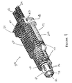
- Figure 4 is a perspective view of the squib connector of Figure 3, shown fully assembled.
- Figures 5A-5E are a series of views depicting the assembly of the preferred embodiment of the invention.
- Figure 6 is a partly sectioned, perspective view of the squib connector of Figure 3 shown seated in the squib socket.
-
- With reference first being made to Figures 1 and 2, the
connector 10 comprises a housing 11, consisting of anupper housing 12 andlower housing 14, aferrite block 16, afemale contact 18 and aground contact 20. The female and ground contacts, respectively, terminate electrical conductors orwires wires holes ferrite block 16. Theferrite block 16 is positioned within acavity 30 in thehousing components wires connector 10. - The interior of the
housing components wire chases ferrite block cavity 30. The wire chases 32, 34 maintain the side-by-side orientation of thewires wire chases cavity 30 are further provided withstress relieving members 36 to relieve stress on thecontacts wires cavity 30, astop boss 38 is provided which preventsfemale contact 18 from moving into the housing 11 when mated with a male contact, such aspin 40 in the squib socket 300 (See Figure 6). - In order to secure the
housing components latching tabs upper housing 12 andlower housing 14, respectively.Latching tabs 42 cooperate withlatching shoulders 46 on thelower housing 14 while latchingtab 48 cooperates withlatching boss 50 onupper housing 12. It will be appreciated that the number, position and form of latching means to secure thehousing components housing components - The
housing components latching ears 52, one disposed on each of the upper andlower housings latching ears 52 cooperate withnotches 54 in thesquib socket 300 to maintain thesquib connector 10 in position within thesocket 300. It will be recognized by those skilled in the art that thehousing components - In the embodiment shown in the Figures, the
female contact 18 comprises a generally rectangular, box-shaped receptacle that is in electrical and mechanical contact with the conductor ofwire 22. Such contacts are well known in the art and need not be discussed in further detail. Examples of such contacts include those described in WO 98/18181 and the Micro Quadlok™ System commercially available from Tyco Electronics, Harrisburg, PA. It will be understood that any suitable female contact may be employed within the scope of the invention. - The
ground contact 20, in the embodiment shown in Figures 1 & 2, comprises a stamped and formed piece of metal in electrical and mechanical contact with the conductor ofwire 24.Ground contact 20, as seen in Figure 1, has atongue portion 55 that is folded back upon itself to form aleaf beam 56. Theleaf beam 56 has a bow shaped bend, giving the leaf beam a resilient property. As seen in Figure 2, when theconnector 10 is assembled, theleaf beam 56 is disposed within aslot 58 in a nose ortip section 60 of housing 11 and projects beyond the housing 11. - When the squib connector is mated with the squib socket, the electrical power connection is made by male contact 40 (Figure 6) being engaged with
female contact 18 viaaperture 62 innose section 60 of theconnector 10. This electrical power connection thus occurs in an orientation that is parallel to the longitudinal axis of theconnector 10. The electrical ground connection occurs betweenleaf beam 56 ofground contact 20 andgrounding surface 64 located within the squib socket 300 (see Figure 6). Because theleaf beam 56 projects away from a side surface of thetip 60, it will be appreciated that the ground connection is oriented transverse to the longitudinal axis of the connector and 90 degrees from the power connection. However, the power and electrical connections still occur in planes that are parallel to one another; i.e., the plane of thegrounding surface 64 is in spaced, substantially parallel relationship to the plane of themale contact 40. It will also be appreciated that the grounding connection occurs external to theconnector 10 while the power connection occurs internal to theconnector 10. - In the embodiment shown in Figure 6, the
grounding surface 64 comprises a annular ring that surrounds thetip 60 of the housing 11. It will be understood that alternative arrangements are possible, although not preferred because then orientation of theconnector 10 relative to thesocket 300 would be required. In the event an oriented arrangement is used, it would be advantageous to provide thehousing components keyway 65 or other indicia of orientation, as seen in Figures 1 and 2. - Turning now to Figures 3-6, the preferred embodiment of the invention will be described. It is noted at the onset that the embodiment of Figures 1-2 is similar in many respects to the preferred embodiment of Figures 3-6 and both share many of the same components. To avoid confusion, the same reference characters will be used for identical components and new reference characters will be used only where the components differ from one embodiment to the other. The description of such components set forth above is equally applicable to the preferred embodiments.
- In the preferred embodiment, the
connector 210 comprises ahousing 211 having upper and lower housing pieces orcomponents nose body 70. Thenose body 70 is a substantially cylindrical shaped member that, when assembled, is partly disposed in thehousing 211. The portion ofnose body 70 that is not disposed in thehousing 211 extends therefrom to form the tip or nose section of the connector, as shown in Figure 4. Thenose body 70 has atip 72 and abase 74. Thebase 74 is provided withslots 78 which cooperate withribs 80 as a means of retaining the nose body in thehousing 211. - As in the previous embodiment, the
housing components ears 52 to secure thesquib connector 210 in thesquib socket 300. In addition, thehousing components cavity 30 for theferrite block 16, and thestrain relief members 36. - The
nose section 70 is provided with alongitudinal bore 82 that is sized to receive therein thefemale contact 18. Theground contact 83, in the preferred embodiment, comprises a cage likemember 84 that is mechanically and electrically connected to the conductor ofwire 24. Thecage 84 comprises a plurality of spaced apartresilient beams 86 arranged in a circular configuration and held together byannular bands 88, 90, one at either end of thebeams 86. Thecage 84 is sized to fit over the section ofnose body 70 that is intermediate thetip 72 and thebase portion 74. When assembled, thecage 84 is positioned outside of thehousing 211, as seen in Figures 4 and 6. - With reference now being made to Figures 5A-5E, the assembly of the
connector 210 will be described. The following description is for illustration only, and should not be construed in any sense as a limitation on the invention. Those skilled in the art will appreciate that alternative processes are available to assemble the connector. Thefemale contact 18 is mechanically and electrically connected, such as by crimping, to thewire 22. Thefemale contact 18 is then inserted into thelongitudinal bore 82 in thenose body 70 from thebase end 74 of the nose body. Theground contact 83 is mechanically and electrically connected, such as by crimping, to thewire 24. Then, thetip 72 of thenose body 70 is inserted into thecage 84 of theground contact 83, as seen in Figure 5B. Thewires ferrite block 16, as seen in Figure 5C. The contacts, ferrite block, nose body and wires are then positioned within thehousing components squib connector 210 is then inserted into thesquib socket 300 whereby themale contact 40 is mated with the female contact, theground contact 86 is mated with groundingsurface 64 and the latchingears 52 engage the latch recesses 54 to secure the squib connector in position.
Claims (11)
- A squib connector assembly (10,210) comprising:a) a housing (11,211) having a longitudinal axis and a tip (60,70) ;b) a female contact (18) disposed within the tip of said housing for mating engagement with a male contact (40); andc) a ground contact comprising at least one resilient spring beam (56,86) disposed on an external surface of the tip of said housing.
- The squib connector of claim 1, wherein the or each spring beam (56,86) is disposed for ground contact at a location transverse to the longitudinal axis of the housing (11,211).
- The squib connector of claim 1 or 2, wherein the or each spring beam (56,86) is positioned for ground contact along a plane spaced from and substantially parallel to the longitudinal axis of the housing(11,211).
- The squib connector of claim 1, 2 or 3, wherein the ground contact comprises a substantially cylindrical cage (84) having a plurality of spring beams (86) disposed in spaced relation and defining a circumference of said cage.
- The squib connector of claim 1, 2 or 3, wherein the ground contact comprises a single spring beam (56).
- The squib connector of any preceding claim, wherein the housing (11,211) comprises an upper housing (12,212) and a lower housing (14,214) secured together.
- The squib connector of claim 7, wherein the upper and lower housings are secured together by latching means (42,46,48) formed integrally with the upper and lower housings.
- The squib connector of claim 6 or 7, including a nose body (70) partially disposed between the upper housing (212) and the lower housing (214), a portion of said nose body projecting beyond the housing and comprising said tip.
- The squib connector of any preceding claim, including a ferrite block (16) disposed within the housing (11,211), said ferrite block being disposed around a portion of a pair of electrical wires (22,24), each of which is electrically and mechanically attached to a respective one of the female contact (18) and the ground contact.
- The squib connector of claim 9, wherein the pair of electrical wires (22,24) is disposed along the longitudinal axis of the housing (11,211).
- The squib connector of any preceding claim, wherein the housing (11,211) comprising latching ears (52) disposed on external surfaces of the housing, said latching ears comprising means for securing the connector in a squib socket (300).
Applications Claiming Priority (2)
| Application Number | Priority Date | Filing Date | Title |
|---|---|---|---|
| US37120 | 2001-10-25 | ||
| US10/037,120 US6609931B2 (en) | 2001-10-25 | 2001-10-25 | Orientationless squib connector assembly |
Publications (2)
| Publication Number | Publication Date |
|---|---|
| EP1309038A1 true EP1309038A1 (en) | 2003-05-07 |
| EP1309038B1 EP1309038B1 (en) | 2005-08-17 |
Family
ID=21892534
Family Applications (1)
| Application Number | Title | Priority Date | Filing Date |
|---|---|---|---|
| EP02257430A Expired - Lifetime EP1309038B1 (en) | 2001-10-25 | 2002-10-25 | Orientationless squib connector assembly for automotive air bag assemblies |
Country Status (8)
| Country | Link |
|---|---|
| US (1) | US6609931B2 (en) |
| EP (1) | EP1309038B1 (en) |
| JP (1) | JP2003187922A (en) |
| KR (1) | KR20030034030A (en) |
| BR (1) | BR0207459A (en) |
| CA (1) | CA2409733C (en) |
| DE (1) | DE60205562T2 (en) |
| ES (1) | ES2246376T3 (en) |
Cited By (1)
| Publication number | Priority date | Publication date | Assignee | Title |
|---|---|---|---|---|
| WO2013092193A1 (en) * | 2011-12-23 | 2013-06-27 | Delphi Connection Systems Holding France | Safety restrain system connector |
Families Citing this family (23)
| Publication number | Priority date | Publication date | Assignee | Title |
|---|---|---|---|---|
| JP2003249308A (en) * | 2002-02-25 | 2003-09-05 | Tyco Electronics Amp Kk | Electrical connector assembly |
| TW550857B (en) * | 2002-06-21 | 2003-09-01 | Yuan Lin | Conductive wire connection device |
| US6809265B1 (en) * | 2003-04-15 | 2004-10-26 | Delphi Technologies, Inc. | Terminal assembly for a coaxial cable |
| US6948976B2 (en) * | 2004-03-01 | 2005-09-27 | Andrew Corporation | Cable and apparatus interface environmental seal |
| US7631839B1 (en) * | 2004-08-20 | 2009-12-15 | Lockheed Martin Corporation | Enhanced multiple instrument distributed aperture sensor |
| US7121883B1 (en) * | 2005-06-06 | 2006-10-17 | John Mezzalingua Associates, Inc. | Coax connector having steering insulator |
| US7160149B1 (en) * | 2005-06-24 | 2007-01-09 | John Mezzalingua Associates, Inc. | Coaxial connector and method of connecting a two-wire cable to a coaxial connector |
| TWI330236B (en) * | 2006-01-30 | 2010-09-11 | Smc Corp | Electromagnetic valve |
| US20080090447A1 (en) * | 2006-10-13 | 2008-04-17 | Lars David Moravy | Wire strain relief structure and method |
| US7841865B2 (en) * | 2008-09-19 | 2010-11-30 | Ivus Industries, Llc | Orientationless spring probe receptacle assembly |
| US7824218B2 (en) * | 2008-09-30 | 2010-11-02 | Amphenol Corporation | Contact holder assembly |
| US7699665B1 (en) * | 2008-10-31 | 2010-04-20 | Cheng Uei Precision Industry Co., Ltd. | Audio plug connector |
| JP4898855B2 (en) * | 2009-02-04 | 2012-03-21 | 矢崎総業株式会社 | connector |
| KR101117968B1 (en) | 2009-11-05 | 2012-02-16 | 주식회사 경신 | Locking device |
| DE202010009766U1 (en) * | 2010-07-02 | 2010-09-16 | Rosenberger Hochfrequenztechnik Gmbh & Co. Kg | Rotatable connector |
| US9106035B2 (en) * | 2012-06-25 | 2015-08-11 | Dish Network L.L.C. | RF connector with push-on connection |
| EP2802042B1 (en) | 2013-05-10 | 2017-07-12 | Orkli, S. Coop. | Thermocouple connector adapted for being connected to a safety gas valve, and thermocouple |
| JP6212775B2 (en) * | 2013-08-09 | 2017-10-18 | 矢崎総業株式会社 | connector |
| CN104466544B (en) * | 2014-12-08 | 2017-02-22 | 小米科技有限责任公司 | Earphone socket, earphone plug, earphones and electronic device |
| US9762007B2 (en) | 2016-02-10 | 2017-09-12 | Dish Network L.L.C. | Push on connector |
| US9787017B1 (en) * | 2016-03-17 | 2017-10-10 | Te Connectivity Corporation | Electrical connector with two-piece cavity insert |
| CN106848679B (en) * | 2017-04-07 | 2023-08-01 | 旭立辰新能源(东莞)有限公司 | Female terminal structure capable of reducing terminal contact impedance |
| TWM629088U (en) * | 2022-02-21 | 2022-07-01 | 崧柏電子有限公司 | Solderless connector |
Citations (2)
| Publication number | Priority date | Publication date | Assignee | Title |
|---|---|---|---|---|
| US5273457A (en) * | 1992-02-25 | 1993-12-28 | Siemens Aktiengesellschaft | Contact arrangement between a coax cable and the blades of a wiring backplane |
| US6203342B1 (en) * | 1996-08-12 | 2001-03-20 | Thomas & Betts International, Inc. | Grounding plate for orientationless squib connector assembly for automotive air bag assemblies |
Family Cites Families (11)
| Publication number | Priority date | Publication date | Assignee | Title |
|---|---|---|---|---|
| US5131869A (en) * | 1990-09-24 | 1992-07-21 | Safco Corporation | Electrical adapter plug |
| US5131680A (en) | 1991-03-19 | 1992-07-21 | Trw Vehicle Safety Systems Inc. | Inflator assembly |
| US5200574A (en) | 1991-04-05 | 1993-04-06 | Morton International, Inc. | Universal squib connector |
| US5241910A (en) | 1991-04-05 | 1993-09-07 | Morton International, Inc. | Universal squib connector for a gas generator |
| US5314345A (en) | 1992-10-09 | 1994-05-24 | Trw Inc. | Electrical connection system with interlock |
| US5409403A (en) | 1993-10-25 | 1995-04-25 | Falossi; Aldo | 360 degree connector system |
| JP3266518B2 (en) | 1996-08-28 | 2002-03-18 | エスエムケイ株式会社 | Plug and jack connection structure |
| US5695357A (en) * | 1996-09-09 | 1997-12-09 | Osram Sylvania Inc. | Cable connector kit, cable connector assembly and related method |
| US6036226A (en) | 1997-02-03 | 2000-03-14 | General Dynamics Armament Systems, Inc. | Inflator capable of modulation air bag inflation rate in a vehicle occupant restraint apparatus |
| US6029995A (en) | 1998-04-09 | 2000-02-29 | Trw Vehicle Safety Systems Inc. | Vehicle occupant protection apparatus |
| TW453528U (en) | 1999-07-02 | 2001-09-01 | Hon Hai Prec Ind Co Ltd | Socket connector |
-
2001
- 2001-10-25 US US10/037,120 patent/US6609931B2/en not_active Expired - Fee Related
-
2002
- 2002-10-24 CA CA2409733A patent/CA2409733C/en not_active Expired - Fee Related
- 2002-10-24 BR BR0207459-1A patent/BR0207459A/en not_active IP Right Cessation
- 2002-10-25 KR KR1020020065523A patent/KR20030034030A/en not_active Ceased
- 2002-10-25 EP EP02257430A patent/EP1309038B1/en not_active Expired - Lifetime
- 2002-10-25 JP JP2002311447A patent/JP2003187922A/en active Pending
- 2002-10-25 ES ES02257430T patent/ES2246376T3/en not_active Expired - Lifetime
- 2002-10-25 DE DE60205562T patent/DE60205562T2/en not_active Expired - Lifetime
Patent Citations (2)
| Publication number | Priority date | Publication date | Assignee | Title |
|---|---|---|---|---|
| US5273457A (en) * | 1992-02-25 | 1993-12-28 | Siemens Aktiengesellschaft | Contact arrangement between a coax cable and the blades of a wiring backplane |
| US6203342B1 (en) * | 1996-08-12 | 2001-03-20 | Thomas & Betts International, Inc. | Grounding plate for orientationless squib connector assembly for automotive air bag assemblies |
Cited By (1)
| Publication number | Priority date | Publication date | Assignee | Title |
|---|---|---|---|---|
| WO2013092193A1 (en) * | 2011-12-23 | 2013-06-27 | Delphi Connection Systems Holding France | Safety restrain system connector |
Also Published As
| Publication number | Publication date |
|---|---|
| JP2003187922A (en) | 2003-07-04 |
| EP1309038B1 (en) | 2005-08-17 |
| CA2409733A1 (en) | 2003-04-25 |
| ES2246376T3 (en) | 2006-02-16 |
| DE60205562D1 (en) | 2005-09-22 |
| DE60205562T2 (en) | 2006-06-01 |
| US6609931B2 (en) | 2003-08-26 |
| US20030082949A1 (en) | 2003-05-01 |
| CA2409733C (en) | 2010-10-05 |
| KR20030034030A (en) | 2003-05-01 |
| BR0207459A (en) | 2004-06-01 |
Similar Documents
| Publication | Publication Date | Title |
|---|---|---|
| US6609931B2 (en) | Orientationless squib connector assembly | |
| US6607406B2 (en) | Nonpolarized electrical connector assembly especially for use as automotive squib connector | |
| US6203342B1 (en) | Grounding plate for orientationless squib connector assembly for automotive air bag assemblies | |
| US6488520B1 (en) | Electrical connector assembly with shorting members | |
| US10236640B2 (en) | Electrical connector for a safety restraint system | |
| US6257918B1 (en) | Wire harness connector having a contact retention plate | |
| US8545262B2 (en) | Shorting clip for an airbag ignition system | |
| US6186805B1 (en) | Short circuit electrical connector | |
| US6604966B1 (en) | Flexible cable electrical connector | |
| US5876231A (en) | Connector for airbag system | |
| EP2162958B1 (en) | Low profile shorting bar for electrical connector | |
| EP3240116B1 (en) | Plug connector | |
| CN115347415B (en) | Electrical connector including connector position assurance element | |
| US9923303B2 (en) | Electrical connector with terminal centering system |
Legal Events
| Date | Code | Title | Description |
|---|---|---|---|
| PUAI | Public reference made under article 153(3) epc to a published international application that has entered the european phase |
Free format text: ORIGINAL CODE: 0009012 |
|
| AK | Designated contracting states |
Designated state(s): AT BE BG CH CY CZ DE DK EE ES FI FR GB GR IE IT LI LU MC NL PT SE SK TR |
|
| AX | Request for extension of the european patent |
Extension state: AL LT LV MK RO SI |
|
| 17P | Request for examination filed |
Effective date: 20030704 |
|
| 17Q | First examination report despatched |
Effective date: 20031010 |
|
| AKX | Designation fees paid |
Designated state(s): DE ES FR GB IT |
|
| GRAP | Despatch of communication of intention to grant a patent |
Free format text: ORIGINAL CODE: EPIDOSNIGR1 |
|
| GRAS | Grant fee paid |
Free format text: ORIGINAL CODE: EPIDOSNIGR3 |
|
| GRAA | (expected) grant |
Free format text: ORIGINAL CODE: 0009210 |
|
| AK | Designated contracting states |
Kind code of ref document: B1 Designated state(s): DE ES FR GB IT |
|
| REG | Reference to a national code |
Ref country code: GB Ref legal event code: FG4D |
|
| REF | Corresponds to: |
Ref document number: 60205562 Country of ref document: DE Date of ref document: 20050922 Kind code of ref document: P |
|
| REG | Reference to a national code |
Ref country code: ES Ref legal event code: FG2A Ref document number: 2246376 Country of ref document: ES Kind code of ref document: T3 |
|
| ET | Fr: translation filed | ||
| PLBE | No opposition filed within time limit |
Free format text: ORIGINAL CODE: 0009261 |
|
| STAA | Information on the status of an ep patent application or granted ep patent |
Free format text: STATUS: NO OPPOSITION FILED WITHIN TIME LIMIT |
|
| 26N | No opposition filed |
Effective date: 20060518 |
|
| PGFP | Annual fee paid to national office [announced via postgrant information from national office to epo] |
Ref country code: DE Payment date: 20091028 Year of fee payment: 8 Ref country code: ES Payment date: 20091026 Year of fee payment: 8 |
|
| PGFP | Annual fee paid to national office [announced via postgrant information from national office to epo] |
Ref country code: FR Payment date: 20091029 Year of fee payment: 8 Ref country code: GB Payment date: 20091026 Year of fee payment: 8 Ref country code: IT Payment date: 20091026 Year of fee payment: 8 |
|
| GBPC | Gb: european patent ceased through non-payment of renewal fee |
Effective date: 20101025 |
|
| PG25 | Lapsed in a contracting state [announced via postgrant information from national office to epo] |
Ref country code: FR Free format text: LAPSE BECAUSE OF NON-PAYMENT OF DUE FEES Effective date: 20101102 |
|
| REG | Reference to a national code |
Ref country code: FR Ref legal event code: ST Effective date: 20110630 |
|
| PG25 | Lapsed in a contracting state [announced via postgrant information from national office to epo] |
Ref country code: GB Free format text: LAPSE BECAUSE OF NON-PAYMENT OF DUE FEES Effective date: 20101025 |
|
| REG | Reference to a national code |
Ref country code: DE Ref legal event code: R119 Ref document number: 60205562 Country of ref document: DE Effective date: 20110502 |
|
| REG | Reference to a national code |
Ref country code: ES Ref legal event code: FD2A Effective date: 20111118 |
|
| PG25 | Lapsed in a contracting state [announced via postgrant information from national office to epo] |
Ref country code: IT Free format text: LAPSE BECAUSE OF NON-PAYMENT OF DUE FEES Effective date: 20101025 |
|
| PG25 | Lapsed in a contracting state [announced via postgrant information from national office to epo] |
Ref country code: ES Free format text: LAPSE BECAUSE OF NON-PAYMENT OF DUE FEES Effective date: 20101026 |
|
| PG25 | Lapsed in a contracting state [announced via postgrant information from national office to epo] |
Ref country code: DE Free format text: LAPSE BECAUSE OF NON-PAYMENT OF DUE FEES Effective date: 20110502 |