EP1308953A2 - Magnetic head load/unload method and magnetic disk drive using the method - Google Patents
Magnetic head load/unload method and magnetic disk drive using the method Download PDFInfo
- Publication number
- EP1308953A2 EP1308953A2 EP02002482A EP02002482A EP1308953A2 EP 1308953 A2 EP1308953 A2 EP 1308953A2 EP 02002482 A EP02002482 A EP 02002482A EP 02002482 A EP02002482 A EP 02002482A EP 1308953 A2 EP1308953 A2 EP 1308953A2
- Authority
- EP
- European Patent Office
- Prior art keywords
- slider
- magnetic disk
- magnetic head
- magnetic
- ramp
- Prior art date
- Legal status (The legal status is an assumption and is not a legal conclusion. Google has not performed a legal analysis and makes no representation as to the accuracy of the status listed.)
- Withdrawn
Links
Images



Classifications
-
- G—PHYSICS
- G11—INFORMATION STORAGE
- G11B—INFORMATION STORAGE BASED ON RELATIVE MOVEMENT BETWEEN RECORD CARRIER AND TRANSDUCER
- G11B21/00—Head arrangements not specific to the method of recording or reproducing
- G11B21/02—Driving or moving of heads
- G11B21/12—Raising and lowering; Back-spacing or forward-spacing along track; Returning to starting position otherwise than during transducing operation
-
- G—PHYSICS
- G11—INFORMATION STORAGE
- G11B—INFORMATION STORAGE BASED ON RELATIVE MOVEMENT BETWEEN RECORD CARRIER AND TRANSDUCER
- G11B5/00—Recording by magnetisation or demagnetisation of a record carrier; Reproducing by magnetic means; Record carriers therefor
- G11B5/48—Disposition or mounting of heads or head supports relative to record carriers ; arrangements of heads, e.g. for scanning the record carrier to increase the relative speed
- G11B5/58—Disposition or mounting of heads or head supports relative to record carriers ; arrangements of heads, e.g. for scanning the record carrier to increase the relative speed with provision for moving the head for the purpose of maintaining alignment of the head relative to the record carrier during transducing operation, e.g. to compensate for surface irregularities of the latter or for track following
- G11B5/60—Fluid-dynamic spacing of heads from record-carriers
- G11B5/6005—Specially adapted for spacing from a rotating disc using a fluid cushion
-
- G—PHYSICS
- G11—INFORMATION STORAGE
- G11B—INFORMATION STORAGE BASED ON RELATIVE MOVEMENT BETWEEN RECORD CARRIER AND TRANSDUCER
- G11B21/00—Head arrangements not specific to the method of recording or reproducing
- G11B21/16—Supporting the heads; Supporting the sockets for plug-in heads
- G11B21/20—Supporting the heads; Supporting the sockets for plug-in heads while the head is in operative position but stationary or permitting minor movements to follow irregularities in surface of record carrier
- G11B21/21—Supporting the heads; Supporting the sockets for plug-in heads while the head is in operative position but stationary or permitting minor movements to follow irregularities in surface of record carrier with provision for maintaining desired spacing of head from record carrier, e.g. fluid-dynamic spacing, slider
-
- G—PHYSICS
- G11—INFORMATION STORAGE
- G11B—INFORMATION STORAGE BASED ON RELATIVE MOVEMENT BETWEEN RECORD CARRIER AND TRANSDUCER
- G11B5/00—Recording by magnetisation or demagnetisation of a record carrier; Reproducing by magnetic means; Record carriers therefor
- G11B5/48—Disposition or mounting of heads or head supports relative to record carriers ; arrangements of heads, e.g. for scanning the record carrier to increase the relative speed
- G11B5/54—Disposition or mounting of heads or head supports relative to record carriers ; arrangements of heads, e.g. for scanning the record carrier to increase the relative speed with provision for moving the head into or out of its operative position or across tracks
Definitions
- the present invention relates to a load/unload mechanism for a magnetic head, or in particular to the operation of controlling the load/unload mechanism smoothly by acquiring information from magnetic disk media.
- a magnetic disk drive is a peripheral device in which a magnetic head writes (records) or reads (reproduces) information into or from at least a rotating magnetic disk medium for exchanging the information with a host system.
- a slider having the magnetic head mounted thereon is undesirably kept on the magnetic disk media at the risk of the slider and the magnetic disk media coming into collision with each other under an external shock that may deteriorate shock resistance performance.
- the method of keeping the slider in a predetermined area of the magnetic disk media when the media stop rotating is also undesirable as an adhesion would develop between the slider having the magnetic head mounted thereon and a specific magnetic disk medium.
- the magnetic disk drive has recently come to employ a load/unload technique for withdrawing the slider (magnetic head) outside of the magnetic disk media.
- the magnetic head In the load operation, the magnetic head is moved onto the magnetic disk media from the position where it is withdrawn and held, while in the unload operation, the magnetic head is moved to the position outside the magnetic disk media where it is withdrawn and held.
- JP-A-11-96708 A technique for controlling the movement of the magnetic head by detecting the loading position of the magnetic head from the data recorded on the magnetic disk media is disclosed in JP-A-11-96708. This technique is such that in the loading process, the moving speed of the magnetic head is suppressed or the magnetic head is stopped thereby to prevent the collision between the magnetic head and the magnetic recording media.
- an actuator having the slider mounted and supported thereon slows down or temporarily stops due to external forces extremely increased when a part of the slider support members including the suspension for supporting the slider rides over the ramp.
- the speed at which the slider support members run into the ramp at the time of unloading is set to a value considerably larger than the theoretical target speed. In this way, the movement of the slider for the load/unload operation has conventionally been controlled only roughly. As a result, the inconveniences such as the collision between the slider and the magnetic disk media have often occurred.
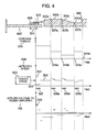
- Fig. 4 can be used also to explain the prior art.
- a part of the support members for the slider that has been in the seek operation over the magnetic disk medium 602 is combined with the ramp, so that the slider is unloaded under the guidance of the ramp.
- a part of the suspension constituting the support members runs into the ramp 608, and therefore the external forces 316 increase so sharply that the slider extremely slows down or temporarily stops on the ramp 608.
- the design speed at which the slider runs into the ramp 608 is set to a value higher than the target speed 503 (324) on the ramp 608.
- the detected speed is high like the target speed 322 on the ramp slant surface 305a.
- the detected speed 504 is decreased below the target speed 503 (detection speed 323), and is seen to take some time (325) before coming to coincide with the target speed 503.
- a speed error occurs between the detected speed 504 and the target speed 503 due to the change of the external forces caused by the gradient change, so that the detected speed is seen to take some time length 326a to 326c before coming to coincide with the target speed 503.
- a part of the support members including the suspension for supporting the slider is combined with the ramp providing the withdrawal/holding means, and the magnetic head is withdrawn following the action of the particular part of the slider support members riding over the ramp.
- the reverse is the case for the load operation, in which the slider lands on the magnetic disk medium following the action of a part of the support members sliding down the ramp from the holding position thereof.
- the component parts of the load/unload mechanism including the ramp and the slider having the magnetic head mounted thereon have geometric and mounting tolerances, so that the external forces acting between the ramp and the slider support members vary from one magnetic disk drive to another. In the case where the slider is moved to the ramp with a simple constant value, therefore, the slider would slow down or temporarily stop thereby making it difficult to withdraw it over the ramp at a steady rate.
- the slider movement is controlled only roughly in the load/unload operation, thereby leading to such inconveniences as the collision between the slider and the magnetic disk media, the friction between or the wear of the ramp member and the slider support members, the generation of dust, etc.
- the slider separated from the magnetic disk media at an insufficiently high position of the ramp collides with the magnetic disk media under a separation shock.
- the accurate velocity control operation has not been performed in spite of the need thereof for withdrawing the slider at a steady rate in the unload operation.
- the magnetic head sometimes misses the servo information in an area on the magnetic disk media where no servo information is written, with the result that the slider support members having the magnetic head mounted thereon and the ramp often collide with each other at a speed higher than the target speed.
- the present inventors have taken note of the fact that the magnetic disk drive controls the velocity by feedback through a VCM (voice coil motor) and a control circuit thereof, and has come to hit an idea that the unload operation, if started at a predetermined reference position outer on the magnetic disk media, can subsequently be accurately controlled. In other words, the position at which the slider is unloaded is detected from the information recorded on the magnetic disk media, whereby the subsequent unload operation is controlled accurately.
- VCM voice coil motor
- An object of the present invention is to provide a technique for carrying out the stable load/unload operation for a magnetic disk drive having a load/unload mechanism, in which an actuator for moving the slider having the magnetic head mounted thereon is prevented from slowing down, temporarily stopping or otherwise changing the speed during the load/unload operation.
- Another object of the invention is to provide a technique for controlling the load/unload operation for the magnetic head, in which the speed at which the slider support members including the suspension run into the ramp is set to a necessary and sufficient level lower than in the prior art thereby to reduce the wear caused by the friction between the ramp and the slider support members such as a suspension tab while at the same time suppressing the generation of dust for an improved reliability.
- Still another object of the invention is to provide a technique for controlling the load/unload operation for the magnetic disk drive and the magnetic head, in which the speed of the slider unloaded and moved following the ramp is constantly maintained at a steady level thereby making it possible to avoid the collision between the slider separated from the magnetic disk media and the magnetic disk media under the shock of separation.
- Yet another object of the invention is to provide a technique for controlling the load/unload operation for the magnetic disk drive and the magnetic head, in which the servo information and other control signals are written in the outer periphery of the magnetic disk media so that the position at which the slider lands on or takes off from the magnetic disk media in the load/unload operation can be recognized accurately by the magnetic disk drive based on the signal from the magnetic head, thereby making it possible to compensate for the values of the voltage or the current supplied to the power amplifier for driving the VCM, measurements and records of other parameters and the recorded values corresponding to the external forces including the friction exerted between the ramp and the slider support members and the suction exerted between the slider and the magnetic disk media.
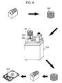
- Fig. 8 The process for fabricating a magnetic disk drive according to this invention is schematically shown in Fig. 8.
- the servo information are written in magnetic disk media 602 by a servo track writer unit 701 before being built in the spindle motor of the magnetic disk drive.
- the servo track writer unit 701 stacks a plurality of magnetic disk media through spacers on a core 703 mounted on the spindle portion 705 and can write the servo information collectively on these magnetic disk media in the block.
- the magnetic disk drive includes a load/unload mechanism.
- the use of the servo track writer unit 701 makes it possible to write the servo information over an area extending to the outer periphery of the magnetic disk media. As a result, the additional amount of the information written in the outer periphery of the media can be increased.
- the ramp is defined as a holding member for holding the slider by the outer peripheral portion or the outside portion of the magnetic disk media.
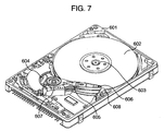
- Fig. 7 shows an internal configuration of a magnetic disk drive having the load/unload mechanism.
- a spindle motor 603 is rotatably incorporated in the magnetic disk drive 601, and the slider having the magnetic head 606 mounted thereon is supported swingably on a carriage 605 so that the magnetic head 606 can record and reproduce the information into and from the magnetic disk media 602 supported on the spindle motor 603.
- the carriage 605 includes a magnetic head 606 at one end thereof and a voice coil at the other end thereof.
- the voice coil makes up a voice coil motor (VCM) 604 or an actuator 607 as a whole which, upon energization thereof, swings the carriage by exerting Lorentz' s force between the magnet and the magnetic field.
- VCM voice coil motor
- the magnetic disk drive 601 (Figs. 7 and 8) according to an embodiment of the invention employs a load/unload mechanism.
- the load/unload mechanism is defined as a mechanism capable of withdrawing (unloading) the magnetic head outside of but not over the magnetic disk media when the magnetic head is not recording or reproducing the information on the one hand, and capable of positioning (loading) the magnetic head on the magnetic disk media as required on the other.
- a part of the suspension constituting a member for supporting the slider with the magnetic head mounted thereon collaborates with the ramp in such a manner that a part of the suspension can move by sliding over the ramp.
- the slider is still attracted to the magnetic disk media even after a part of the slider support members begins to climb up the ramp, and once a part of the support members has climbed up to a predetermined portion of the ramp, the slider is released from the magnetic disk media. This separation enables the slider to vibrate in the neighborhood of the magnetic disk media and the ramp while being supported by the slider supports member.
- the time point when a part of the slider support members begins to climb up the ramp and the time point when the slider is released from the magnetic disk media in the unload operation are different from each other.
- the slider has landed on the magnetic disk media before a part of the slider support members has completely slid down the ramp in the load operation.
- an unload speed control system 500 (Fig. 6) is used.
- the control system 500 is roughly divided into a feedback control system 501 and a feedforward control system 502.
- the feedback control system 501 includes:
- the feedforward control system 502 adds the compensation value 515 corresponding to the external forces 316 (Figs. 4 and 5) acting on the actuator 607 in the unload operation to the output of the phase compensator 506 of the feedback control system 501 and inputs it to the D/A converter 507.
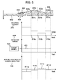
- the servo information is written in a range called the landing zone 304 (Figs. 4 and 5) where the magnetic head 606 first lands on the media 602 from the ramp 608 (Fig. 7) in the load operation of the magnetic head.
- the take-off track the track number (hereinafter referred to as the take-off track) on the magnetic disk media for the magnetic head to take off from the magnetic disk media 602 under the guidance of the ramp 608.
- the accurate position on the magnetic disk media where the magnetic head takes off can be determined. Due to the mounting tolerance allowed for the component parts of the mechanism, the position at which the magnetic head lands or takes off in the load/unload operation is varied from one magnetic disk drive to another. To determine the take-off position and the landing position accurately, however, is tantamount to obviating the inconveniences due to the tolerance by causing the control system of the magnetic disk drive to function appropriately.
- Fig. 4 the external forces 316 acting on the actuator 607 (Fig. 7), the back electromotive voltage of the voice coil motor 604 (Fig. 7), the detected speed 504 of the actuator 607 obtained from the back electromotive voltage/speed converter 513 (Fig. 6) and the voltage 106 applied to the power amplifier are indicated for each part of the ramp extending from the slant surface 305a to the second flat portion 305 in the unload operation.
- the input or the output of the power amplifier may be a change in current.
- a series of unload operation are performed until the end of first measurement of the initial value when the measurements are stored in the magnetic disk drive 601.
- the ramp 608 is divided into predetermined areas, and in accordance with the external forces acting on each of the areas, the target speed, the voltage applied to the power amplifier and other initial values are measured and stored.
- the target speed is considerably dispersed in the starting portion of each area (the left side of each area in Fig. 4) and the applied voltage to the power amplifier is changed to a correspondingly large extent.
- the external forces are large and the target speed fluctuates when a part of the suspension supporting the magnetic head (slider) slides up the ramp slant surface 305a, while the detected speed is stabilized once the same part begins to climb up the slope.
- the applied voltage 106 to the power amplifier is considerably large as indicated by 330 in the process of unloading from the landing zone 304.
- Numerals 326a, 326b, 326c in Fig. 4 designate the standby time before stabilization of the target speed, and upon the lapse of this time, the target speed is stabilized.
- the magnetic head 606, together with a part of the suspension reaches the ramp home position 306 corresponding to a second ramp flat portion 305d.
- each area both the target speed and the applied voltage to the power amplifier are stabilized. These stabilized values are stored as initial values for the unload operation in the magnetic disk drive 601.
- the end portion of each area is defined as the portion where the movement of the magnetic head 606 ends in the direction thereof.
- the magnetic disk drive 601 can detect the accurate landing track for the magnetic head 606.
- the magnetic disk drive 601 upon acquisition of an unload instruction (101), performs the seek operation aimed at a specified track (take-off track) located on the outer periphery of the magnetic disk media (102).
- the magnetic disk drive 601 thus starts to detect the back electromotive voltage of the voice coil motor thereby to validate the functions of the speed control system (103), while at the same time starting to acquire the servo information on the magnetic disk media from the output of the magnetic head 606 (104).
- the position of the take-off track is detected from the output of the magnetic head, and the time is initialized in the step of setting the initial values for the unload operation thereby to initialize predetermined parameter values (105).
- the unload operation is performed in which the magnetic head, together with the suspension providing the slider support members, leaves the media 602 under the guidance of the ramp.
- the position of the take-off track may be on the landing track read in advance by the magnetic head at the time of the load operation.
- the take-off track and the landing track both exist in the landing zone 304.
- Character t designates an appropriate sampling interval, or a time interval at which the parameters and data are fetched by the magnetic disk drive 601.
- This sampling interval t doubles as an expression of time.
- each time point is determined by such an expression as after the lapse of time T1 (319a), after the lapse of time T2 (319b), after the lapse of time T3 (319c), after the lapse of time T4 (319d) or the like counted from the take-off track, the landing track or other specified track.
- the time schedule for the whole process of setting initial values is divided into the ramp slant surface 305a to the second ramp flat portion 305d and managed by the magnetic disk drive 601 with a table as to the time point to which each area corresponds.
- the applied voltage values to the power amplifier are recorded.
- the initial values for the unload operation are thus completely set.
- the initial values for the load operation can be set in similar fashion.
- the magnetic disk drive 601 acquires an unload instruction from the host system (101 in Fig. 1), the magnetic head is caused to perform the seek operation on the take-off track or the landing track (102).
- the velocity control operation is started (103) while at the same time detecting the servo information from the magnetic head (104).
- the position of the take-off track is detected from the output of the magnetic head and the predetermined parameters are initialized (105).
- the initial values (the values stored in the compensation table) set in the flash ROM is accessed.
- the count operation is started with the take-off track as a reference, and the voltage of the initial value is applied to the power amplifier 508 (Fig. 6) as a voltage to compensate for the external forces.
- the following relation is held.
- the magnetic head can be withdrawn from the end portion 303, through the positions 305a, 305b, 305c to the position 305d (home position) of the magnetic disk medium on the ramp 608 at a predetermined target speed 503.
- the target speed 503 may assume different values at positions 305a to 305d.
- the required time during which the voltage 106 is applied to the power amplifier is calculated as follows.
- a general-purpose microcomputer or other electronic circuits are used for the calculation taking into account the positions of the take-off track and the landing track, the sampling time point or time length t, the gradient, distance, friction coefficient and other surface conditions for each area of the ramp 608 and the target speed 503 for the unload operation on the ramp 608.
- the optimum contents of the compensation table 515 for withdrawing the magnetic head at a predetermined speed on the ramp 608 may be changed by the temperature change in the ambience around the magnetic disk drive 601 or the secular variation of the internal mechanism and circuits. Each time the unload operation or the magnetic disk drive 601 is started or at predetermined time intervals, therefore, the contents of the compensation table 515 in the flash ROM may be recorded or updated.
- the unload operation may be repeated a plurality of times so that the applied voltage 106 to the power amplifier is measured to set a plurality of initial values and an average value thereof may be stored in the compensation table 515 in the flash ROM.
- the speed error 505 (Fig. 6) of the actuator 607 caused by the change in the external forces acting on the actuator in the unload control operation is suppressed, and while maintaining a predetermined target speed 503 (Fig. 5), the actuator 607 can be moved smoothly from the end portion 303 of the magnetic disk medium on the ramp 608 to the home position 306.
- the magnetic head is unloaded in such a manner that while the actuator (including the slider, the suspension and the magnetic head) is prevented from slowing down extremely or stopping temporarily on the ramp, an always constant speed is maintained thereby to assure a smooth, stable load/unload operation.
- the residual vibration generated in the slider running into the ramp can be suppressed, and therefore the collision between the slider and the magnetic disk media can be avoided at an insufficiently high ramp position.
- the take-off track or the landing track for the magnetic head can be accurately detected, and therefore the magnetic head is prevented from running into the ramp at higher than the target speed, thereby contributing to an improved reliability.
Landscapes
- Supporting Of Heads In Record-Carrier Devices (AREA)
- Moving Of Head For Track Selection And Changing (AREA)
Abstract
Description
Claims (7)
- A control method for a magnetic disk drive (601) including magnetic disk media (602), a slider mounting thereon a magnetic head (606) facing said magnetic disk media (602), support members for supporting said slider, an actuator (607) for rotatably supporting said support members, an electronic circuit for controlling drive of said actuator (607) and signal processing, and a holding member for holding said slider, the method comprising the steps of:unload step for starting process for holding said slider on said holding member while reading information from said magnetic disk media (602) through said magnetic head (606); andload step for causing said magnetic head (606) to read the information from said magnetic disk media (602) while following said holding member, after starting said process for causing said slider to land from said holding member onto said magnetic disk media (602).
- The control method according to Claim 1, wherein
said process for holding said slider following said holding member is divided into two or more steps in advance, and at the end of movement of said slider in each of said two or more steps, the value of a voltage or a current for driving said actuator (607) is stored. - The control method according to Claim 1, wherein
said process for holding said slider following said holding member is divided into two or more steps in advance, and the value of a voltage or a current for driving said actuator (607) is constant in each of said two or more steps. - A magnetic disk drive (601), comprising:magnetic disk media (602);a slider mounting thereon a magnetic head (606) facing said magnetic disk media (602);support members for supporting said slider;an actuator (607) for rotatably supporting said support members; andan electronic circuit for controlling drive of said actuator (607) and signal processing, the electronic circuit havinga function of setting a parameter for driving said actuator (607) in each of said two or more steps for moving said slider while following said holding member anda function of performing a mechanical load/unload operation smoothly using said set parameters.
- A method for controlling a magnetic disc device (601) including a magnetic disc (602), a slider (605) carrying a magnetic head (606), an actuator (607) for positioning the slider, and a holder (608) for holding said slider when the magnetic head is unloaded from said magnetic disc,
including the following step:unloading said magnetic head from said magnetic disc wherein holding of said slider (605) by said holder (608) starts while reading information from said magnetic disc (602) through said magnetic head (606). - A method for controlling a magnetic disc device (601) including a magnetic disc (602), a slider (605) carrying a magnetic head (606), an actuator (607) for positioning the slider, and a holder (608) for holding said slider when the magnetic head is unloaded from said magnetic disc,
including the following step:loading said magnetic head to said magnetic disc wherein holding of said slider (605) by said holder (608) terminates while reading information from said magnetic disc (602) through said magnetic head (606). - A method according to claim 5 or 6, wherein said holder is a ramp (608) and said informations is a reference signal used to control a speed of the actuator (607) during movement of the slider (605) relative to the ramp.
Applications Claiming Priority (2)
| Application Number | Priority Date | Filing Date | Title |
|---|---|---|---|
| JP2001335967A JP2003141839A (en) | 2001-11-01 | 2001-11-01 | Load / unload method and magnetic disk drive using the same |
| JP2001335967 | 2001-11-01 |
Publications (2)
| Publication Number | Publication Date |
|---|---|
| EP1308953A2 true EP1308953A2 (en) | 2003-05-07 |
| EP1308953A3 EP1308953A3 (en) | 2004-05-19 |
Family
ID=19150881
Family Applications (1)
| Application Number | Title | Priority Date | Filing Date |
|---|---|---|---|
| EP02002482A Withdrawn EP1308953A3 (en) | 2001-11-01 | 2002-02-01 | Magnetic head load/unload method and magnetic disk drive using the method |
Country Status (5)
| Country | Link |
|---|---|
| US (1) | US6920007B2 (en) |
| EP (1) | EP1308953A3 (en) |
| JP (1) | JP2003141839A (en) |
| KR (1) | KR100488834B1 (en) |
| CN (1) | CN1416128A (en) |
Cited By (1)
| Publication number | Priority date | Publication date | Assignee | Title |
|---|---|---|---|---|
| EP1439528A1 (en) * | 2003-01-16 | 2004-07-21 | Samsung Electronics Co., Ltd. | Method of marking and updating optimal unlatch profile for hard disk drive |
Families Citing this family (27)
| Publication number | Priority date | Publication date | Assignee | Title |
|---|---|---|---|---|
| US20050007688A1 (en) * | 2003-07-09 | 2005-01-13 | Joseph Chang | Dual speed control to reduce audible noise and protect head during unload in ramp load drives with pawl latch |
| JP4408213B2 (en) | 2003-11-18 | 2010-02-03 | 東芝ストレージデバイス株式会社 | Storage device and actuator movement control method |
| JP4226998B2 (en) * | 2003-11-20 | 2009-02-18 | 株式会社東芝 | Disk storage |
| KR100532483B1 (en) | 2003-12-12 | 2005-12-02 | 삼성전자주식회사 | Calibration method and apparatus therefor |
| US7236331B2 (en) * | 2003-12-30 | 2007-06-26 | Matsushita Electric Industrial Co., Ltd. | System and method to provide a ramp having a location which is transitioning from a first grade to a second grade for removing a read/write head from a media |
| JP4404353B2 (en) * | 2004-05-25 | 2010-01-27 | 株式会社日立製作所 | Disk array that suppresses disk failures |
| SG125151A1 (en) * | 2005-02-24 | 2006-09-29 | Seagate Technology Llc | Velocity control system for an actuator assembly |
| JP2006252601A (en) * | 2005-03-08 | 2006-09-21 | Hitachi Global Storage Technologies Netherlands Bv | Magnetic disk apparatus and control method thereof |
| US7209310B1 (en) * | 2005-07-25 | 2007-04-24 | Western Digital Technologies, Inc. | Disk drive identifying starting track by performing multiple load operations |
| JP2007080409A (en) * | 2005-09-15 | 2007-03-29 | Hitachi Global Storage Technologies Netherlands Bv | Disk drive and control method thereof |
| JP2007115309A (en) * | 2005-10-19 | 2007-05-10 | Hitachi Global Storage Technologies Netherlands Bv | Magnetic disk unit |
| KR100734293B1 (en) * | 2005-12-14 | 2007-07-02 | 삼성전자주식회사 | Voice coil motor driving method of hard disk drive, head unloading device and recording medium suitable for this |
| JP2007334986A (en) * | 2006-06-14 | 2007-12-27 | Fujitsu Ltd | Control device, storage device, and head withdrawal method |
| JP4724055B2 (en) * | 2006-06-15 | 2011-07-13 | 東芝ストレージデバイス株式会社 | Control device, storage device, and head retraction control method |
| JP2007335015A (en) * | 2006-06-15 | 2007-12-27 | Fujitsu Ltd | Ramp position detecting device, lamp position detecting method and storage device |
| JPWO2008146349A1 (en) * | 2007-05-25 | 2010-08-12 | 東芝ストレージデバイス株式会社 | Ramp member for recording disk drive device, recording disk drive device, and head actuator member position detection method |
| US7869155B1 (en) * | 2007-06-08 | 2011-01-11 | Western Digital Technologies, Inc. | Ramp detection during servo-writing of a disk for a disk drive |
| US7573670B1 (en) * | 2007-09-27 | 2009-08-11 | Western Digital Technologies, Inc. | Disk drive seeking to OD track and then ramping velocity to implement fast unload |
| US7715145B2 (en) * | 2008-09-16 | 2010-05-11 | Seagate Technology Llc | Variable spindle speed for ramp unload |
| US8315005B1 (en) | 2009-11-06 | 2012-11-20 | Western Digital Technologies, Inc. | Ramp detection by profile sweep method utilizing integrator values |
| US8300348B1 (en) | 2010-06-25 | 2012-10-30 | Western Digital Technologies, Inc. | Disk drive detecting disk boundaries using microactuator |
| US8687312B1 (en) | 2010-11-30 | 2014-04-01 | Western Digital Technologies, Inc. | Edge detection for disk drives |
| US8861126B1 (en) | 2011-09-20 | 2014-10-14 | Western Digital Technologies, Inc. | Disk drive detecting when head is on ramp |
| US8786976B1 (en) | 2011-09-20 | 2014-07-22 | Western Digital Technologies, Inc. | Disk drive detecting when head is on ramp |
| US9064537B1 (en) | 2013-09-13 | 2015-06-23 | Western Digital Technologies, Inc. | Disk drive measuring radial offset between heads by detecting a difference between ramp contact |
| US9355666B1 (en) | 2013-09-30 | 2016-05-31 | Western Digital Technologies, Inc. | Disk drive measuring stroke difference between heads by detecting a difference between ramp contact |
| JP2018055756A (en) * | 2016-09-30 | 2018-04-05 | ルネサスエレクトロニクス株式会社 | Control device, magnetic disk control system, and control method for controlling disk storage device |
Family Cites Families (18)
| Publication number | Priority date | Publication date | Assignee | Title |
|---|---|---|---|---|
| JP2633739B2 (en) * | 1991-03-29 | 1997-07-23 | 株式会社東芝 | Data recording / reproducing device |
| US5455723A (en) * | 1994-06-02 | 1995-10-03 | International Business Machines Corporation | Method and apparatus for ramp load and unload |
| US5633767A (en) * | 1995-06-06 | 1997-05-27 | International Business Machines Corporation | Adaptive and in-situ load/unload damage estimation and compensation |
| US5949608A (en) * | 1996-06-05 | 1999-09-07 | Mobile Storage Technology Inc. | Time dependent velocity-controlled disk drive actuator system |
| KR100255207B1 (en) * | 1997-01-28 | 2000-05-01 | 윤종용 | How to Stable Unlatch Control of Hard Disk Drives |
| JP3016476B2 (en) * | 1997-06-27 | 2000-03-06 | インターナショナル・ビジネス・マシーンズ・コーポレイション | Head mechanism control device, disk drive device, and head unload control method |
| JPH1196708A (en) | 1997-09-19 | 1999-04-09 | Toshiba Corp | Head load control device and head load control method for disk storage device |
| JP2000042434A (en) * | 1998-07-30 | 2000-02-15 | Shinnakano Industry Co Ltd | Rice-polishing tank |
| US6320717B1 (en) * | 1998-10-30 | 2001-11-20 | Iomega Corporation | Velocity limited loading of read heads onto disk drive media |
| JP3607513B2 (en) * | 1998-11-30 | 2005-01-05 | 株式会社東芝 | Speed correction value calibration method applied to a head load / unload type disk device |
| US6590731B1 (en) * | 1998-12-11 | 2003-07-08 | Iomega Corporation | System and method for adaptive soft head loading of disk drive head onto disk medium |
| US6054833A (en) * | 1999-05-10 | 2000-04-25 | Iomega Corporation | Disk drive having improved head-velocity control, and method therefor |
| JP3688522B2 (en) | 1999-07-30 | 2005-08-31 | 株式会社日立グローバルストレージテクノロジーズ | Control method of magnetic disk drive |
| JP2001052458A (en) * | 1999-08-10 | 2001-02-23 | Toshiba Corp | Magnetic disk drive and carriage movement control method during head unload operation |
| JP3856608B2 (en) | 1999-11-29 | 2006-12-13 | 富士通株式会社 | Actuator speed control device and storage device |
| KR100667735B1 (en) * | 2000-01-22 | 2007-01-11 | 삼성전자주식회사 | Actuator moving speed control device and method |
| JP4127595B2 (en) * | 2000-03-30 | 2008-07-30 | 株式会社東芝 | Magnetic disk device, information writing device, and load / unload radius position detection method |
| JP3757098B2 (en) * | 2000-06-01 | 2006-03-22 | 富士通株式会社 | Disk device and disk medium |
-
2001
- 2001-11-01 JP JP2001335967A patent/JP2003141839A/en active Pending
-
2002
- 2002-02-01 EP EP02002482A patent/EP1308953A3/en not_active Withdrawn
- 2002-02-07 US US10/067,401 patent/US6920007B2/en not_active Expired - Fee Related
- 2002-02-19 KR KR10-2002-0008619A patent/KR100488834B1/en not_active Expired - Fee Related
- 2002-02-20 CN CN02105687A patent/CN1416128A/en active Pending
Cited By (1)
| Publication number | Priority date | Publication date | Assignee | Title |
|---|---|---|---|---|
| EP1439528A1 (en) * | 2003-01-16 | 2004-07-21 | Samsung Electronics Co., Ltd. | Method of marking and updating optimal unlatch profile for hard disk drive |
Also Published As
| Publication number | Publication date |
|---|---|
| US6920007B2 (en) | 2005-07-19 |
| US20030081343A1 (en) | 2003-05-01 |
| EP1308953A3 (en) | 2004-05-19 |
| KR100488834B1 (en) | 2005-05-11 |
| CN1416128A (en) | 2003-05-07 |
| JP2003141839A (en) | 2003-05-16 |
| KR20030038292A (en) | 2003-05-16 |
Similar Documents
| Publication | Publication Date | Title |
|---|---|---|
| EP1308953A2 (en) | Magnetic head load/unload method and magnetic disk drive using the method | |
| JP3856608B2 (en) | Actuator speed control device and storage device | |
| JP3607513B2 (en) | Speed correction value calibration method applied to a head load / unload type disk device | |
| US6643088B1 (en) | Magnetic disk drive and method of controlling a movement of carriage in an unload operation of head | |
| TWI480866B (en) | Servo system and its operation method | |
| CN1501390A (en) | Tape cassette | |
| US7031093B2 (en) | Storage medium and method for actuator movement control | |
| US7576939B2 (en) | Discontinuous mode back EMF measurement | |
| US20030161065A1 (en) | Method and apparatus for controlling the actuator of the head-positioning system provided in a disk drive | |
| JP2003085902A (en) | Magnetic disk drive | |
| US6388413B1 (en) | Head switch seek on disc drives with multiple recording heads | |
| US7430093B2 (en) | Seek control method of hard disk drive, recording medium storing method and hard disk drive adopting method | |
| CN101030385B (en) | Method and apparatus for driving vcm unloading hdd head | |
| US20030117741A1 (en) | Method and apparatus for loading head onto disk medium from ramp in disk drive | |
| JP4180582B2 (en) | Storage device | |
| US7609474B2 (en) | Seek control method, seek control device and disk device | |
| JP4799913B2 (en) | Data storage device, parameter determination method and method for determining position control signal value of head | |
| US12499906B1 (en) | Magnetic disk drive and control method of the same | |
| US12579999B2 (en) | Speed control of actuator arm and spindle in a data storage device | |
| JP4237163B2 (en) | Actuator speed control device and storage device | |
| KR100640607B1 (en) | A method for controlling an abnormal state restoration of a data storage system and a disk drive using the same | |
| JP2005085322A (en) | Magnetic disk apparatus and magnetic head slider position control method | |
| CN116778979A (en) | disk device | |
| JP5415147B2 (en) | Disk drive and its clearance measurement method | |
| JP2000090615A (en) | Disk storage device and head flying height measuring method applied to the same |
Legal Events
| Date | Code | Title | Description |
|---|---|---|---|
| PUAI | Public reference made under article 153(3) epc to a published international application that has entered the european phase |
Free format text: ORIGINAL CODE: 0009012 |
|
| AK | Designated contracting states |
Designated state(s): AT BE CH CY DE DK ES FI FR GB GR IE IT LI LU MC NL PT SE TR |
|
| AX | Request for extension of the european patent |
Extension state: AL LT LV MK RO SI |
|
| RAP1 | Party data changed (applicant data changed or rights of an application transferred) |
Owner name: HITACHI GLOBAL STORAGE TECHNOLOGIES JAPAN, LTD. |
|
| PUAL | Search report despatched |
Free format text: ORIGINAL CODE: 0009013 |
|
| AK | Designated contracting states |
Kind code of ref document: A3 Designated state(s): AT BE CH CY DE DK ES FI FR GB GR IE IT LI LU MC NL PT SE TR |
|
| AX | Request for extension of the european patent |
Extension state: AL LT LV MK RO SI |
|
| 17P | Request for examination filed |
Effective date: 20040614 |
|
| AKX | Designation fees paid |
Designated state(s): DE FR GB |
|
| 17Q | First examination report despatched |
Effective date: 20060822 |
|
| STAA | Information on the status of an ep patent application or granted ep patent |
Free format text: STATUS: THE APPLICATION IS DEEMED TO BE WITHDRAWN |
|
| 18D | Application deemed to be withdrawn |
Effective date: 20120724 |