EP1308744A2 - Verfahren zur passiven Ortung von schallabstrahlenden Zielen - Google Patents
Verfahren zur passiven Ortung von schallabstrahlenden Zielen Download PDFInfo
- Publication number
- EP1308744A2 EP1308744A2 EP02020286A EP02020286A EP1308744A2 EP 1308744 A2 EP1308744 A2 EP 1308744A2 EP 02020286 A EP02020286 A EP 02020286A EP 02020286 A EP02020286 A EP 02020286A EP 1308744 A2 EP1308744 A2 EP 1308744A2
- Authority
- EP
- European Patent Office
- Prior art keywords
- distance
- target
- level
- determined
- frequency
- Prior art date
- Legal status (The legal status is an assumption and is not a legal conclusion. Google has not performed a legal analysis and makes no representation as to the accuracy of the status listed.)
- Granted
Links
Images


Classifications
-
- G—PHYSICS
- G01—MEASURING; TESTING
- G01S—RADIO DIRECTION-FINDING; RADIO NAVIGATION; DETERMINING DISTANCE OR VELOCITY BY USE OF RADIO WAVES; LOCATING OR PRESENCE-DETECTING BY USE OF THE REFLECTION OR RERADIATION OF RADIO WAVES; ANALOGOUS ARRANGEMENTS USING OTHER WAVES
- G01S3/00—Direction-finders for determining the direction from which infrasonic, sonic, ultrasonic, or electromagnetic waves, or particle emission, not having a directional significance, are being received
- G01S3/80—Direction-finders for determining the direction from which infrasonic, sonic, ultrasonic, or electromagnetic waves, or particle emission, not having a directional significance, are being received using ultrasonic, sonic or infrasonic waves
- G01S3/802—Systems for determining direction or deviation from predetermined direction
- G01S3/808—Systems for determining direction or deviation from predetermined direction using transducers spaced apart and measuring phase or time difference between signals therefrom, i.e. path-difference systems
- G01S3/8083—Systems for determining direction or deviation from predetermined direction using transducers spaced apart and measuring phase or time difference between signals therefrom, i.e. path-difference systems determining direction of source
-
- G—PHYSICS
- G10—MUSICAL INSTRUMENTS; ACOUSTICS
- G10K—SOUND-PRODUCING DEVICES; METHODS OR DEVICES FOR PROTECTING AGAINST, OR FOR DAMPING, NOISE OR OTHER ACOUSTIC WAVES IN GENERAL; ACOUSTICS NOT OTHERWISE PROVIDED FOR
- G10K11/00—Methods or devices for transmitting, conducting or directing sound in general; Methods or devices for protecting against, or for damping, noise or other acoustic waves in general
- G10K11/18—Methods or devices for transmitting, conducting or directing sound
- G10K11/26—Sound-focusing or directing, e.g. scanning
- G10K11/34—Sound-focusing or directing, e.g. scanning using electrical steering of transducer arrays, e.g. beam steering
- G10K11/341—Circuits therefor
- G10K11/346—Circuits therefor using phase variation
-
- G—PHYSICS
- G01—MEASURING; TESTING
- G01S—RADIO DIRECTION-FINDING; RADIO NAVIGATION; DETERMINING DISTANCE OR VELOCITY BY USE OF RADIO WAVES; LOCATING OR PRESENCE-DETECTING BY USE OF THE REFLECTION OR RERADIATION OF RADIO WAVES; ANALOGOUS ARRANGEMENTS USING OTHER WAVES
- G01S11/00—Systems for determining distance or velocity not using reflection or reradiation
- G01S11/14—Systems for determining distance or velocity not using reflection or reradiation using ultrasonic, sonic, or infrasonic waves
Definitions
- the invention relates to a method for the passive location of sound-emitting targets in the preamble of claim 1 defined genus.
- the invention has for its object to provide a method of to improve the type mentioned above so that it at low Signal-to-noise ratios still good estimates of Locating parameter provides.
- the inventive method has the advantage that by the Taking the reciprocal of the distance equal to the distance Curvature of the incident on the transducer array wavefront is, the output signals of the converter statistically evaluated can be.
- the use of the statistical nature of Measured variables still allow for poor signal-to-noise conditions good compared to the known methods Estimates of the measured quantities. This is associated with a good Accuracy of location results much faster is achieved, the time to reach the desired accuracy in particular of the length or Aperture of the transducer arrangement and the useful / disturbance ratio (Signal-to-noise ratio, SNR). Own maneuvers or Target maneuvers are not required.
- the method of the invention can increase the efficiency of Enlightenment tasks are significantly improved. Already after Perform a first bearing and corresponding Focusing along the beam becomes a first Approximate estimate of the destination in a few seconds brought about. A first reliable result from the destination you get already after several estimates. These are neither own maneuvers nor maneuvers of the target required.
- the inventive method is due to its short Integration time relatively insensitive to low temporal coherence lengths and by an almost continuous scanning of the wavefront by the density Transducer assignment also insensitive to low spatial Coherence lengths.
- the low requirements for coherence the sound propagation bring the advantage that the process is robust against a series of disturbances caused by complex Sound propagation conditions, e.g. Multipath, Temperature gradients, formation of sound channels and Water stratifications are caused.
- Transducer assembly is very simple, since the accuracy of Detection of transducer positions, as in a Distance determination by correlation of received signals three transducers or transducer groups are provided (US 4,910 719), not necessary in the method according to the invention are because not only three, but many points on the received wave front to calculate the target distance be used.
- the method according to the invention is preferably the entire length of the transducer assembly for forming the focal points used a subdivision of existing transducers in individual transducer groups is omitted.
- the achieved by Focusing the focal points formed by the focus signals brings the advantage of an additional interference suppression, so that in particular adjacent targets do not measure the result affect.
- targets are at a bad payload / sturgeon ratio the focus signals detected better because of the Formation of the level profile over the reciprocal of the distance Level maxima clearly pronounced and also such goals in Level profile can be reliably detected.
- the invention Method is characterized by the possibility of an exact Target separation and target location, even if two different loud targets on neighboring beacons be detected by the transducer assembly.
- the focusing of the transducer assembly is the focusing of the transducer assembly only on such Focus points made on already as target bearings detected reflected beams lie.
- the must Converter arrangement exclusively on the latter
- Target bearings are focused according to a few directional beams which increases the computational effort and the computing time considerably reduced.
- the target bearings are in conventionally determined by means of a DF system by for each bearing direction in the receiving sector of the transducer assembly formed a directional characteristic with the transducer assembly becomes.
- suitable phase and / or time delays of electrical output signals of the converter and konphase Addition of the delayed output signals Group signals of the directional characteristics formed. Group signals with a significant level provide picking beams with target bearings. Are the target bearings known and possibly Verified, so only the removal of the detected targets on the different bearing beams be determined.
- each level curve as a function of the distance inverse value the gradient of the function by formation of the first derivative the level profile and the curvature of the function by education the second derivative of the level profile respectively after the Distance sweep detected.
- the level value at which the gradient is zero and the curvature is negative the level maximum on the beam.
- the level maximum associated distance return value is after inverse as Target distance indicated. This type of determination of Target distance is accurate at incident sound signals, the have a sufficient SNR.
- the determination of the distance inversion value is subject to a statistical error due to a noise superimposed on the useful portion of the focus signal.
- the distance-dependent focus signal is formed for different distances in each case by a sum of delayed output or received signals of the transducer of the transducer assembly.
- the distance-dependent level profile of the focus signal is a sum of cosine functions that shows a quadratic dependence on the distance inverse value over a series expansion for small arguments of the cosine where P 0 is the amplitude of the focus signal P (R -1 ), R is the distance value, f is the frequency, L is the length of the transducer array and c is the speed of sound.
- the integration time used to form the level curve is finite, so that the amplitude P is 0 superimposed on the level curve, a noise amplitude, which produces a statistical error in the determination of the Absisse of the level maximum and thus in the determination of the distance inverse.
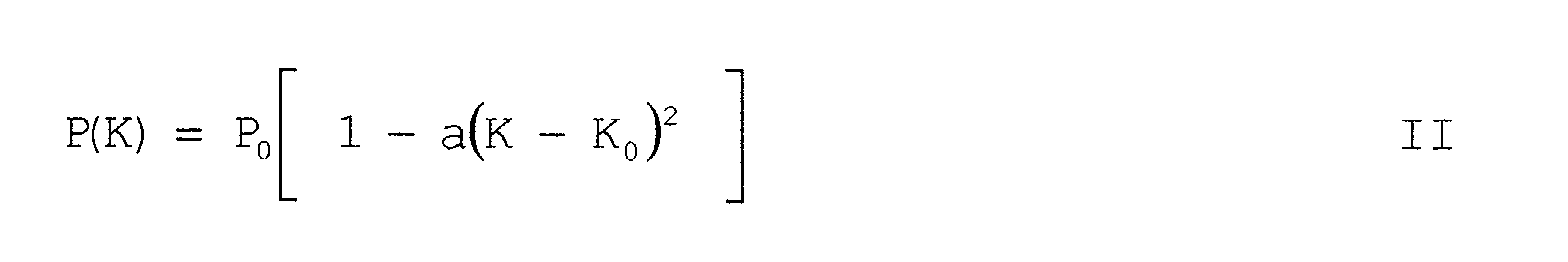
- the focus signal may be approximated in the far field by a second order polynomial when the range sweep R -1 is replaced by the curvature K.
- K - K 0 is the distortion of the curvature of the wavefront caused by the noise, ie the statistical error ⁇ K of the curvature.
- the relative statistical error of the distance value is a function of distance, with increasing frequency falls and inversely proportional to the radical
- the useful / disturbance ratio of the focus signal is that as well is frequency dependent.
- the useful / interference ratio of the focus signal can be from the Spectrum of the focus signal containing the target and spectra of focus signals of adjacent focal points in which no Target is included and which is a small distance to the target exhibit, with not too large spatial anisotropy of Noise can be estimated. With this utility / interference ratio becomes the relative statistical error of the distance calculated.
- the useful / interference ratio of the focus signal is particularly simple the useful / interference ratio of one of the reception signals of the converter taking into account a specifiable time-bandwidth product to calculate.
- the effective, Bearing angle dependent length of the aperture and the number of Converter is thus the relative statistical error with a Evaluation of the spectrum of only a single received signal possible.
- An advantageous embodiment of the invention provides that the focusing of the transducer on all Fokal matters is made on the order of discrete bearing angles staggered, the receiving sector grid-like covering Beilstrahlen lie. For every beam, the levels of the focus signals in dependence on the Bearing angles determined. In addition to the level curve as a function of Distance sweep will also change the level as a function formed of the bearing angle. In the level curve as a function of Peilwinkels maxima are detected and from the associated Distance sweep values are estimated the target ranges. In this further embodiment of the method, the Focusing signals for a grid of bearing angles and Distance sweep determined so that the receiving sector can be searched for goals, the acoustic energy radiate.
- the maxima in the level curve as Function of the bearing angle by calculation of the gradient and the curvature of the level profile are determined. Those Level values where the gradient is zero and the curvature is negative, are defined as maxima.
- the maxima associated bearing angles are specified as target bearings.
- the level profile in the receiving sector as a two-dimensional function of the distance inversion value and determines the bearing angle and for maximum detection gradient and Curvature by partial differentiation of the two-dimensional function according to the distance sweep value and the bearing angle calculated.
- this embodiment of the invention is a destination location and separation even at low Nutz / Störssen, lower Coherence length due to disturbances in the propagation medium and at complex sound propagation conditions, e.g. Multipath propagation, possible.
- the invention is by computer simulation as pattern distribution one two-dimensional function depending on Distance sweep and bearing angle for one or more Targets calculated, and this pattern distribution is compared with the for the reception sector specific two-dimensional function of Level curve compared by convolution.
- This will be Maxima, by receiving reverberation in neighboring Directional radiation a sloping course above the receiving reciprocal value and generate bearing angle, suppressed and not at the Target detection detects what is desired as a level of different distances and different bearing angles shows up, can not correspond to a real goal.
- a noise immunity is achieved however, neighboring targets are still recognized and be located separately.
- a further embodiment of the invention is in the two-dimensional pattern distribution and in the two-dimensional level curve in each case the curvature calculated, and the curvatures of leveling and Pattern distribution are folded.
- the convolution integral then existing peaks are detected.
- the the peaks assigned values of distance sweep value and bearing angle are used to determine the location of the destination. to Calculation of curvatures is based on the function of Level curve and on the function of the pattern distribution of Laplace operator applied.
- the peaks associated Distance sweep also a same statistical Filtering as already stated above is.
- the median of the peaks associated distance returns from a specified Number of last measurements made.
- the target range is then the reciprocal of the median.
- a Confidence interval from the median of the absolute value Deviation from the median formed in the estimation educated.
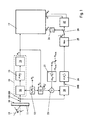
- a transducer arrangement 10 also called a receiving antenna, with spaced-apart, electroacoustic transducers 11 is used.
- the transducer assembly 10 is a linear antenna with a plurality of equidistantly juxtaposed transducers 11, as known for example as a towed antenna (towed array) or attached to the hull side antenna (flank array), sometimes called Bordwandstreamer known.
- a receiving sector is spanned within which incident sound, which is emitted from sound-forming targets and propagates in the water, is received by the transducers 11.
- the transducers 11 are connected in a conventional manner to a direction finding system 13 in which, based on the electrical output signals of the transducers 11 - hereinafter referred to as received signals - the direction of incidence of the sound and thus the bearing direction is determined to the targets.
- the direction finder 13 includes in a known manner a direction generator 14, a signal processing block 15 and a level detector 16.
- the direction generator 14 in a known manner, the received signals of the converter 11 time and / or phase delayed, in such a way that taking into account the desired incident or Bearing direction ⁇ j all received signals of the converter 11 konphas.
- the received receive signals in each direction are added to a group signal, and the level signal of the group signal is stored in association with the incident or bearing direction ⁇ j .
- the level detector 16 detects the largest level signal and outputs the maximum level signals of the group signals associated bearing angle ⁇ z as target bearings, which are fed to a display device 17 and shown in this numerically and graphically.
- the received signals ie in turn the electrical output signals of the transducers 11, are fed to a so-called focusing beamformer 18.
- the received signals of the transducers 11 are focused by defined time and / or phase delays on focal points, which are arranged one behind the other on a fixed by the bearing angle ⁇ z DF beam 19 and are offset by discrete distance stages to the center of the transducer assembly 11 radially.
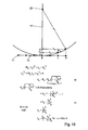
- Fig. 10 The calculation of the required time delays for focusing the transducer arrangement 10 on a Fokalddling 20 lying on the beam Peilstrahl 19 is shown in Fig. 10.
- the focal point 20 is at a distance R k from the center of the transducer assembly 10
- the transducer assembly 10 is designed as a linear array with 2N equidistantly arranged transducers 11.
- the time delays for the received signals of the n transducers 11 are obtained from the transit times for the distances y n of the n transducers 11 from a circular arc drawn around the focal point 20, the tangent of which touches the center of the transducer assembly 10.
- x n is the distance of the n-th transducer 11 from the center of the transducer assembly 10, and c is the speed of sound.
- ⁇ n X 2 n 2Cr k calculated.
- ⁇ n 1 2Cr k (x 2 n - x 2 N ) where x n the distance of the nth transducer and x N the distance of the outermost transducer 11 is in each case from the center of the transducer assembly 10.
- the calculation of the delay time ⁇ n as a function of distance reciprocal R k -1 is carried out in the Delay time calculator 21 (FIG. 1) for a plurality of focal points 20 on the DF beam 19.
- non-real, negative distances are introduced as auxiliary quantities corresponding to negative curvatures of the wavefront, which occur due to the static nature of the received signals and in an expectant Estimate must be taken into account.
- the range sweep range covered with the assumed focal points 20 excludes the near range between + R min and -R min , where R min is an allowable minimum distance from the transducer assembly 10 where locating makes sense.
- For an absolute return value R k -1 which is the same for the same positive and negative curvatures, there are delay times ⁇ n (R k -1 ), which are equal in magnitude and differ only by the sign.
- the received signals of the transducers 11 must still be changed by the delay times ⁇ i resulting from the angle of incidence or bearing ⁇ j .
- the delay time calculator 12 of the direction-finding system 13 is thereto applied to a gate circuit 22 which is controlled by the direction-finding system 13 and only those delay times i ⁇ lets through, which causes such a delay of the reception signals of the transducer 11, that the direction-finding beam 19 is below a pivot angle the target bearing ⁇ z corresponds.
- a summer 23 the delay times ⁇ i ( ⁇ z ) from the delay time calculator 21 with the delay times ⁇ n (R k -1 ) from the delay time calculator 12 in the correct assignment to the individual transducers 11 of the transducer assembly 10 is added, and the resulting actual Delay times are supplied to the focusing beamformer 18.
- the received signals of the transducers 11 are decelerated by the delay times calculated above for each of the bearing system 13 as a target bearing ⁇ z and the resulting konphasen received signals added, wherein for each focal point 20 on the beam 19 a so-called. Focus signal is generated.
- the levels P of the focus signals in dependence on the distance inverse of R k -1 is determined which is a measure of the curvature of the light incident on the transducer assembly 10 wavefront of a sound wave generated by a lying in the focal point 20 source.
- the resulting function of the level profile over the range return value R k -1 is shown by way of example for a direction finding beam 19 located at a bearing angle ⁇ z in FIG.
- the determination of the maximum in the level profile P (R k -1 ) as a function of the range return value R k -1 is carried out in such a way that for each target bearing ⁇ Z the gradient by forming the first derivative of the function and the curvature by forming the second derivative of the Function calculated in each case after the distance sweep value R k -1 and that level is output as a level maximum, in which the gradient is zero and the curvature is negative.
- the distance sweep value R Z -1 output by the maximum searcher is not supplied to the reciprocal generator 26, but to a statistical filter 27, which is illustrated by switching the switch 28 shown only symbolically in the block diagram of FIG.
- the statistical filter 27 used is preferably a running median filter, a so-called running median, which is unbiased in the inverse distance space (R -1 ) and exhibits a minimal variance.
- the target distance R z is estimated by taking the median of the range sweep distances R z -1 detected as the target distances from a fixed number of last measurements and taking the reciprocal thereof.
- the estimated distance R z is in turn fed to the display device 17 and displayed there numerically and graphically.
- another statistical filter 27 may be used, in which z.
- the statistical estimation of the target distance R z is made such that the arithmetic mean of the range sweep distances R z -1 detected as target distances is formed from a fixed number of last measurements and the inverse is formed therefrom.
- an Confidence interval (range of confidence) KI for the Estimated distance value determines what the median of absolute deviation of distance sweep values from before described median over in the past determined range return values is formed.
- a large Value of the confidence interval shows that the Zielentfernungsliden have large fluctuations, ie are not stable and therefore do not enjoy much trust.
- the confidence interval it is also possible to specify an Error window for expected target range.
- the confidence interval is the display device 17th supplied and shown there.
- a filter arrangement 109 for the received signals of the converter 11 is selectively connected, which is shown in FIG.
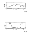
- the useful / disturbing ratio is determined in an arithmetic circuit 110 and multiplied by a prescribable time-bandwidth-width product, which takes into account an integration time for the level determination of the buzzer signal, and the number of transducers 11.
- the computer circuit 110 supplies the frequency-dependent useful / disturbing ratio SNR B of the focus signal, the course of which is shown in FIG. 3 over the frequency as a spectrum.
- c is the speed of sound
- f is the frequency
- L is the length of the effective aperture, which is dependent on the bearing angle ⁇ z
- SNR B is the useful / interference ratio of the focus signal.
- the error calculation circuit 111 is controlled by the bearing angle ⁇ z that the direction-finding system 13 supplies.
- the method 5 illustrated by the block diagram of FIG. And described below, modified for passive location of sound-emitting targets is far modified are not such as advance information on the direction of incidence of light emitted from the target sound used as the data detected by the direction-finding system 13 target bearings ⁇ , but the receiving sector in front of the transducer assembly 10 is searched completely for existing sound sources.
- the receiving sector in front of the transducer assembly 10 is searched completely for existing sound sources.
- a grid of bearing angles ⁇ j and distance Rker R k -1 formed, and for each focal point 20, which is determined by the grid coordinates generated by the focusing beamformer 18, a focus signal.
- the required delay times are formed as described above in the delay time calculator 12 and the delay time calculator 21, added in the summing element 23 and fed to the focusing beamformer 18.
- the beamformer 18 generates a focus signal by congruently adding the received signals for each focal point, which is defined by a bearing angle ⁇ j and a distance sweep value R k -1 .
- the level P of the focus signals is determined as a function of the distance reversal value R k -1 and, unlike in the method described above, also as a function of the bearing angle ⁇ j , and the level profile P (as in the method described above).
- ⁇ j , R k -1 ) is formed as a two-dimensional function of the distance sweep value R k -1 and the bearing angle ⁇ j .
- This two-dimensional function P (R k -1, ⁇ j) is shown as an example in the diagram of Fig. 7. It can be clearly seen that in the assumed example maxima occur in the level profile over the distance sweep value R k -1 and in the level course over the sweep angle ⁇ j .
- the direction finder 13 and the focusing beamformer 15 form a function computer 115, as indicated in FIG. 2, which determines the two-dimensional function of the level profile P (R k -1 , ⁇ j , f) supplies narrowband for selected frequencies f as a function of the distance sweep value R k -1 and the sweep angle ⁇ j .
- a realization of this function calculator 115 is possible in the time domain by estimating the covariance matrix.
- the level profile P (R k -1 , ⁇ j , f) is to be estimated by calculating a cross power density Matirx, if the receive signals are present as complex received spectra at the output frequency analysis circuit 114 via a Fourier transform.
- a direction formation and simultaneous focusing at a frequency distribution of the received signals both in the time domain, as well as in the frequency domain is feasible.
- the Laplace operator is applied to this function in the arithmetic block 29, so that the curvature of the level profile as a two-dimensional function of the range return value R k -1 and the bearing angle ⁇ j is obtained.
- a two-dimensional function M ( ⁇ j ; R k -1 ) of distance sweep value R k -1 and sweep angle ⁇ j for at least one target is calculated as a pattern distribution, and in calculation block 31 its curvature is calculated by using the Laplacian operator.
- the pattern distribution corresponds to the level profile for a point target in transverse direction at infinite distance, ie curvature 0 and level 1. This ensures that the folding does not shift the targets in bearing or distance and the amplitude of a target is not changed.
- a beam path in R -1 and ⁇ a Gaussian beam profile is used, wherein the beam profile corresponds to the profile of the level of a focusing transducer arrangement as a function of the distance to the focal point.
- the curvature of the level curve is convolved with the curvature of the pattern distribution or pattern function M (R k -1 , ⁇ j ).
- the two-dimensional convolution of the curvature of the level profile with the curvature of the theoretical pattern distribution makes weak sound sources within the receiving sector stand out more strongly in the convolution integral, since they stand out more clearly from the noise background.
- FIG. 9 shows, by way of example, the convolution integral as a result of the convolutions of the curves for a scenario underlying the level profile in FIG. 8. While a clear maximum at -38 ° and a much smaller maximum at + 37 ° can be seen in the level profile as a function of the bearing angle (FIG. 8), a maximum at 8 ° could also be assumed.
- the convolution integral according to FIG. 9 confirms the maximum at -38 ° and allows the maximum + 37 ° to emerge much more strongly. In contrast, the range of -10 ° to + 20 ° with respect to the same range in the level profile (Fig.
- the convolution integral resulting from the convolution is fed to a peak detector 33, which detects the peaks and outputs for each peak the associated distance sweep value R z -1 and the associated sweep angle ⁇ z of the respective target.
- the target bearing ⁇ z and the target distance R z , the latter in turn taken at the reciprocal former 26, are supplied to the display device 17 and displayed there numerically and graphically.
- an estimate for the distance R z is given only after a statistical filtering of the range sweep values R z -1 estimated in the individual measurements.
- the peak detector 33 supplies the distance sweep value R z -1 associated with a respective target bearing ⁇ z to the statistical filter 27 in which the filtering is carried out in the same way as already described.
- the estimated value of the target distance R z as well as the associated confidence interval KI are supplied to the display device 17 and displayed there numerically and graphically.
- a pattern distribution can be applied to the calculation be dispensed with entirely and (j ⁇ , R k -1) in the space formed in the function block 24, two-dimensional level profile P by partial differentiation of the two-dimensional function on the distance inverse R -1 and bearing angle ⁇ gradient and curvature are calculated.
- the maximum values R z -1 and bearing angles ⁇ z are output as maxima, in which the gradient is zero and the curvature is negative.
- the Laplace operator is also used here.
- the inventive method is not on the above limited embodiments described. So can as Converter arrangement uses any receiving antenna be, even a towed antenna, if it is guaranteed that the aperture of the antenna is large enough to the desired Achieve resolution.
- a so-called surface array can not only targets in the of the transducer assembly 10th or the receiving antenna spanned in the horizontal plane Reception sector, but in a three-dimensional space sector be detected and located.
- the same Signal processing, as he is in for a Horizontal plane extending linear array described is, then, if necessary, also in terms of frequency selected receive signals from in the vertical direction be carried out in a stacked transducers.
- the level profile of the focus signals in Dependency of the received return value and a spatial one Bearing angle which determines the position of the target in azimuth and elevation determined as a two-dimensional function of Distance sweep and the spatial bearing angle formed become.
- the Laplace operator is used as well as a two-dimensional folding with a corresponding Pattern distribution performed.
- the signal processing can be carried out with both analog and digital signals. If the signals are present in discrete-time form with the sampling frequency f s , then the number of samples by which the sampled signal must be delayed is calculated from the transit time differences for delaying the received signals. After the delay, all the received signals are also added, so that the focusing effect of the method is achieved by the consequent addition of the sound waves originating from the same direction of incidence.
- the energy used the focus signals the energy used the focus signals.
- the power or the amplitude of the focus signals as a measure of the level can be used.
Abstract
Description
- Rmin gewält, wobei Rmin eine zugelassene Mindestentfernung von der Wandleranordnung ist. Der unendlich großen Entfernung, bei der eine ebene Wellenfront empfangen wird und der Fokuspunkt im Unendlichen liegt, wird damit der Krümmungswert der Wellenfront bzw. der Entfernungskehrwert Null zugeordnet. Die Mindestentfernung bestimmt die maximale positive und negative Krümmung und damit den Wertebereich des Entfernungskehrwerts. Durch diese Maßnahme erhält man eine symmetrische Kurve des Pegelverlaufs im Bereich eines Pegelmaximums, aus der sich der Entfernungskehrwert beim Maximum, der die Zielentfernung liefert, sehr viel genauer bestimmen läßt, z.B. durch Näherung der Umgebung des Maximums an eine Parabel und Bestimmen des Scheitelpunkts dieser Parabel. Damit lassen sich auch relativ flach ausgeprägte Maxima, die auf leisen oder weit entfernten Schallquellen basieren, detektieren und genau orten.

- Fig. 1
- ein Blockschaltbild einer Schaltungsanordnung zur Erläuterung des Verfahrens zur passiven Zielortung,
- Fig. 2
- eine Filteranordnung zum Einfügen in das Blockschaltbild gemäß Fig. 1,
- Fig. 3
- ein Spektrum des Nutz/Störverhältnisses,
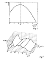
- Fig. 4
- einen Verlauf eines frequenzabhängignen relativen statistischen Fehlers der Entfernung
- Fig. 5
- eine gleiche Darstellung eines Blockschaltbildes wie in Fig. 1 für ein modifiziertes Verfahren,
- Fig. 6
- ein Diagramm des Pegels von in der Schaltungsanordnung gemäß Fig. 1 gebildeten Fokussignalen als Funktion des Kehrwerts der Entfernung von auf einem Peilstrahl liegenden Fokalpunkten von der Wandleranordnung,
- Fig. 7
- ein Diagramm des zweidimensionalen Verlaufs des Pegels der in der Schaltungsanordnung gemäß Fig. 5 gebildeten Fokussignale in Abhängigkeit von dem Kehrwert der Entfernung von im Empfangssektor gebildeten Fokalpunkten von der Wandleranordnung und in Abhängigkeit von dem Peilwinkel der Fokalpunkte,
- Fig. 8
- einen Schnitt des Diagramms in Fig. 7 bei R-1=0,
- Fig. 9
- ein Diagramm des Pegelverlaufs in Fig. 8 nach Faltung der Krümmung des Pegelverlaufs in Fig. 5 mit der Krümmung einer Musterverteilung,
- Fig. 10
- die mathematische Herleitung der Zeitverzögerung für die Ausgangssignale der Wandler zum Fokussieren der Wandleranordnung auf einen Fokalpunkt in der Entfernung Rk von der Wandleranordnung.
Verzögerungszeitrechner 21 (Fig. 1) und zwar für eine Vielzahl von Fokalpunkten 20 auf dem Peilstrahl 19. Dabei werden als Hilfgrößen nicht reale, negative Entfernungen eingeführt, die negativen Krümmungen der Wellenfront entsprechen, die aufgrund der statischen Natur der Empfangssignale auftreten und bei einer erwartungstreuen Schätzung berücksichtigt werden müssen. Der mit den angenommenen Fokalpunkten 20 abgedeckte Bereich für den Entfernungskehrwert schließt den Nahbereich zwischen + Rmin und - Rmin aus, wobei Rmin eine zugelassene Mindestentfernung von der Wandleranordnung 10 ist, in der eine Ortung sinnvoll ist. Für einen betragsmäßig gleichen Entfernungskehrwert Rk -1 also für gleiche positive und negative Krümmungen ergeben sich Verzögerungszeiten Δτn(Rk -1), die betragsmäßig gleich sind und sich lediglich durch das Vorzeichen unterscheiden.
Claims (23)
Applications Claiming Priority (2)
| Application Number | Priority Date | Filing Date | Title |
|---|---|---|---|
| DE10153444 | 2001-10-30 | ||
| DE10153444A DE10153444C1 (de) | 2001-10-30 | 2001-10-30 | Verfahren zur passiven Ortung von schallabstrahlenden Zielen |
Publications (3)
| Publication Number | Publication Date |
|---|---|
| EP1308744A2 true EP1308744A2 (de) | 2003-05-07 |
| EP1308744A3 EP1308744A3 (de) | 2004-02-04 |
| EP1308744B1 EP1308744B1 (de) | 2005-07-27 |
Family
ID=7704159
Family Applications (1)
| Application Number | Title | Priority Date | Filing Date |
|---|---|---|---|
| EP02020286A Expired - Lifetime EP1308744B1 (de) | 2001-10-30 | 2002-09-11 | Verfahren zur passiven Ortung von schallabstrahlenden Zielen |
Country Status (5)
| Country | Link |
|---|---|
| EP (1) | EP1308744B1 (de) |
| AT (1) | ATE300744T1 (de) |
| DE (2) | DE10153444C1 (de) |
| DK (1) | DK1308744T3 (de) |
| ES (1) | ES2244706T3 (de) |
Cited By (1)
| Publication number | Priority date | Publication date | Assignee | Title |
|---|---|---|---|---|
| CN114152679A (zh) * | 2021-10-28 | 2022-03-08 | 航天材料及工艺研究所 | 一种超低温液体环境下的钛合金气瓶声发射二维平面定位方法 |
Families Citing this family (2)
| Publication number | Priority date | Publication date | Assignee | Title |
|---|---|---|---|---|
| DE102008053302B4 (de) * | 2008-10-27 | 2014-02-13 | Dirk Püschel | Vorrichtung und Verfahren zur Lokalisierung und/oder Separierung einer physikalischen Quelle in einem Wellenfeld und ein diesbezügliches Computerprogrammprodukt |
| RU2608583C1 (ru) * | 2016-01-26 | 2017-01-23 | Александр Николаевич Прокаев | Способ определения местоположения и параметров движения объекта по измерениям угловых координат |
Citations (3)
| Publication number | Priority date | Publication date | Assignee | Title |
|---|---|---|---|---|
| EP0288374A1 (de) * | 1987-04-24 | 1988-10-26 | Thomson-Csf | Passives Telemetrie-Verfahren mittels Schall |
| US5680371A (en) * | 1995-07-31 | 1997-10-21 | Arete Engineering Technologies Corporation | Broadband sonar method and apparatus for use with conventional sonar arrays |
| EP0962784A2 (de) * | 1998-06-05 | 1999-12-08 | STN ATLAS Elektronik GmbH | Verfahren zur passiven Bestimmung von Zieldaten |
-
2001
- 2001-10-30 DE DE10153444A patent/DE10153444C1/de not_active Expired - Fee Related
-
2002
- 2002-09-11 DK DK02020286T patent/DK1308744T3/da active
- 2002-09-11 ES ES02020286T patent/ES2244706T3/es not_active Expired - Lifetime
- 2002-09-11 EP EP02020286A patent/EP1308744B1/de not_active Expired - Lifetime
- 2002-09-11 AT AT02020286T patent/ATE300744T1/de not_active IP Right Cessation
- 2002-09-11 DE DE50203734T patent/DE50203734D1/de not_active Expired - Lifetime
Patent Citations (3)
| Publication number | Priority date | Publication date | Assignee | Title |
|---|---|---|---|---|
| EP0288374A1 (de) * | 1987-04-24 | 1988-10-26 | Thomson-Csf | Passives Telemetrie-Verfahren mittels Schall |
| US5680371A (en) * | 1995-07-31 | 1997-10-21 | Arete Engineering Technologies Corporation | Broadband sonar method and apparatus for use with conventional sonar arrays |
| EP0962784A2 (de) * | 1998-06-05 | 1999-12-08 | STN ATLAS Elektronik GmbH | Verfahren zur passiven Bestimmung von Zieldaten |
Cited By (1)
| Publication number | Priority date | Publication date | Assignee | Title |
|---|---|---|---|---|
| CN114152679A (zh) * | 2021-10-28 | 2022-03-08 | 航天材料及工艺研究所 | 一种超低温液体环境下的钛合金气瓶声发射二维平面定位方法 |
Also Published As
| Publication number | Publication date |
|---|---|
| EP1308744A3 (de) | 2004-02-04 |
| EP1308744B1 (de) | 2005-07-27 |
| ES2244706T3 (es) | 2005-12-16 |
| ATE300744T1 (de) | 2005-08-15 |
| DK1308744T3 (da) | 2005-10-31 |
| DE10153444C1 (de) | 2003-02-20 |
| DE50203734D1 (de) | 2005-09-01 |
Similar Documents
| Publication | Publication Date | Title |
|---|---|---|
| DE60309748T2 (de) | System und Verfahren zur Rauschunterdrückung in vorverarbeiteten Radardaten | |
| EP3534178B1 (de) | Radargerät mit gruppenantenne und verfahren zur quelllokalisation durch eine zweidimensionale radargruppenantenne | |
| EP0802427A2 (de) | Verfahren zum aufwandgünstigen Bestimmen einer Impulsantwort eines hochauflösenden bandbegrenzten Radarkanals | |
| DE10129726A1 (de) | Verfahren zum Bestimmen von Zieldaten | |
| EP1308744B1 (de) | Verfahren zur passiven Ortung von schallabstrahlenden Zielen | |
| DE19745370A1 (de) | Verfahren und Vorrichtung zur Bestimmung einfallender Empfangsleistung oder -energie wenigstens eines Signales in wenigstens einer vorgebbaren Beobachtungsrichtung sowie Empfangsanlage | |
| EP1271175B1 (de) | Verfahren zum Bestimmen der Zielposition eines schallabstrahlenden Ziels | |
| EP1034630B1 (de) | Verfahren und messanordnung zur messung der eigenschaften von funkkanälen | |
| DE3322500A1 (de) | Verfahren zum passiven bestimmen von zieldaten eines fahrzeugs | |
| DE10153443C1 (de) | Verfahren zur passiven Ortung von schallabstrahlenden Zielen | |
| DE3200820C2 (de) | ||
| DE4206570C2 (de) | Ultraschall-Geschwindigkeitsmesser | |
| EP0715182B1 (de) | Verfahren zum Peilen schallabstrahlender oder schallreflektierender Ziele | |
| DE102011117591B4 (de) | Verfahren und Vorrichtung zum Korrigieren systematischer Peilfehler | |
| EP2333574B1 (de) | Messgenauigkeitsverbesserungsverfahren, Messgenauigkeitsverbesserungsvorrichtung und Sonaranlage | |
| EP1034631B1 (de) | Verfahren und messanordnung zur messung der eigenschaften von funkkanälen | |
| EP0962784B1 (de) | Verfahren zur passiven Bestimmung von Zieldaten | |
| EP1160584B1 (de) | Verfahren zum Bestimmen von Richtung und/ oder Entfernung reflektierender Zielorte | |
| EP0412248B1 (de) | Verfahren zum passiven Bestimmen von Zieldaten | |
| DE3345021A1 (de) | Passives verfahren zur schaetzung von zustandsgroessen eines bewegten, schallimpulse ins wasser abstrahlenden ziels | |
| DE102009042967A1 (de) | Verfahren und Vorrichtung zum Peilen von schallabstrahlenden Zielen | |
| DE102017100909B4 (de) | Schätzung eines Einfallswinkels | |
| DE3445373A1 (de) | Vorrichtung zur richtungsbildung beim empfang von wellenenergie | |
| WO2023152077A1 (de) | Mikrofonsystem und computerprogrammprodukt zum ermitteln einer ursprungsrichtung von schallsignalen und fahrzeug mit einem derartigen mikrofonsystem | |
| DE102022201395A1 (de) | Ermitteln einer Ursprungsrichtung von Schallsignalen |
Legal Events
| Date | Code | Title | Description |
|---|---|---|---|
| PUAI | Public reference made under article 153(3) epc to a published international application that has entered the european phase |
Free format text: ORIGINAL CODE: 0009012 |
|
| AK | Designated contracting states |
Designated state(s): AT BE BG CH CY CZ DE DK EE ES FI FR GB GR IE IT LI LU MC NL PT SE SK TR |
|
| AX | Request for extension of the european patent |
Extension state: AL LT LV MK RO SI |
|
| RAP1 | Party data changed (applicant data changed or rights of an application transferred) |
Owner name: ATLAS ELEKTRONIK GMBH |
|
| PUAL | Search report despatched |
Free format text: ORIGINAL CODE: 0009013 |
|
| AK | Designated contracting states |
Kind code of ref document: A3 Designated state(s): AT BE BG CH CY CZ DE DK EE ES FI FR GB GR IE IT LI LU MC NL PT SE SK TR |
|
| AX | Request for extension of the european patent |
Extension state: AL LT LV MK RO SI |
|
| 17P | Request for examination filed |
Effective date: 20040207 |
|
| AKX | Designation fees paid |
Designated state(s): AT BE BG CH CY CZ DE DK EE ES FI FR GB GR IE IT LI LU MC NL PT SE SK TR |
|
| GRAP | Despatch of communication of intention to grant a patent |
Free format text: ORIGINAL CODE: EPIDOSNIGR1 |
|
| GRAS | Grant fee paid |
Free format text: ORIGINAL CODE: EPIDOSNIGR3 |
|
| GRAA | (expected) grant |
Free format text: ORIGINAL CODE: 0009210 |
|
| AK | Designated contracting states |
Kind code of ref document: B1 Designated state(s): AT BE BG CH CY CZ DE DK EE ES FI FR GB GR IE IT LI LU MC NL PT SE SK TR |
|
| PG25 | Lapsed in a contracting state [announced via postgrant information from national office to epo] |
Ref country code: CZ Free format text: LAPSE BECAUSE OF FAILURE TO SUBMIT A TRANSLATION OF THE DESCRIPTION OR TO PAY THE FEE WITHIN THE PRESCRIBED TIME-LIMIT Effective date: 20050727 Ref country code: FI Free format text: LAPSE BECAUSE OF FAILURE TO SUBMIT A TRANSLATION OF THE DESCRIPTION OR TO PAY THE FEE WITHIN THE PRESCRIBED TIME-LIMIT Effective date: 20050727 Ref country code: TR Free format text: LAPSE BECAUSE OF FAILURE TO SUBMIT A TRANSLATION OF THE DESCRIPTION OR TO PAY THE FEE WITHIN THE PRESCRIBED TIME-LIMIT Effective date: 20050727 Ref country code: IE Free format text: LAPSE BECAUSE OF FAILURE TO SUBMIT A TRANSLATION OF THE DESCRIPTION OR TO PAY THE FEE WITHIN THE PRESCRIBED TIME-LIMIT Effective date: 20050727 Ref country code: SK Free format text: LAPSE BECAUSE OF FAILURE TO SUBMIT A TRANSLATION OF THE DESCRIPTION OR TO PAY THE FEE WITHIN THE PRESCRIBED TIME-LIMIT Effective date: 20050727 Ref country code: EE Free format text: LAPSE BECAUSE OF FAILURE TO SUBMIT A TRANSLATION OF THE DESCRIPTION OR TO PAY THE FEE WITHIN THE PRESCRIBED TIME-LIMIT Effective date: 20050727 |
|
| REG | Reference to a national code |
Ref country code: GB Ref legal event code: FG4D Free format text: NOT ENGLISH |
|
| REG | Reference to a national code |
Ref country code: CH Ref legal event code: EP |
|
| REG | Reference to a national code |
Ref country code: IE Ref legal event code: FG4D Free format text: LANGUAGE OF EP DOCUMENT: GERMAN |
|
| REF | Corresponds to: |
Ref document number: 50203734 Country of ref document: DE Date of ref document: 20050901 Kind code of ref document: P |
|
| PG25 | Lapsed in a contracting state [announced via postgrant information from national office to epo] |
Ref country code: CY Free format text: LAPSE BECAUSE OF FAILURE TO SUBMIT A TRANSLATION OF THE DESCRIPTION OR TO PAY THE FEE WITHIN THE PRESCRIBED TIME-LIMIT Effective date: 20050911 Ref country code: AT Free format text: LAPSE BECAUSE OF NON-PAYMENT OF DUE FEES Effective date: 20050911 |
|
| PG25 | Lapsed in a contracting state [announced via postgrant information from national office to epo] |
Ref country code: BE Free format text: LAPSE BECAUSE OF NON-PAYMENT OF DUE FEES Effective date: 20050930 Ref country code: MC Free format text: LAPSE BECAUSE OF NON-PAYMENT OF DUE FEES Effective date: 20050930 Ref country code: LU Free format text: LAPSE BECAUSE OF NON-PAYMENT OF DUE FEES Effective date: 20050930 |
|
| PG25 | Lapsed in a contracting state [announced via postgrant information from national office to epo] |
Ref country code: BG Free format text: LAPSE BECAUSE OF FAILURE TO SUBMIT A TRANSLATION OF THE DESCRIPTION OR TO PAY THE FEE WITHIN THE PRESCRIBED TIME-LIMIT Effective date: 20051027 Ref country code: GR Free format text: LAPSE BECAUSE OF FAILURE TO SUBMIT A TRANSLATION OF THE DESCRIPTION OR TO PAY THE FEE WITHIN THE PRESCRIBED TIME-LIMIT Effective date: 20051027 |
|
| REG | Reference to a national code |
Ref country code: DK Ref legal event code: T3 |
|
| REG | Reference to a national code |
Ref country code: SE Ref legal event code: TRGR |
|
| GBT | Gb: translation of ep patent filed (gb section 77(6)(a)/1977) |
Effective date: 20051031 |
|
| REG | Reference to a national code |
Ref country code: ES Ref legal event code: FG2A Ref document number: 2244706 Country of ref document: ES Kind code of ref document: T3 |
|
| REG | Reference to a national code |
Ref country code: IE Ref legal event code: FD4D |
|
| ET | Fr: translation filed | ||
| PLBE | No opposition filed within time limit |
Free format text: ORIGINAL CODE: 0009261 |
|
| STAA | Information on the status of an ep patent application or granted ep patent |
Free format text: STATUS: NO OPPOSITION FILED WITHIN TIME LIMIT |
|
| 26N | No opposition filed |
Effective date: 20060428 |
|
| PG25 | Lapsed in a contracting state [announced via postgrant information from national office to epo] |
Ref country code: LI Free format text: LAPSE BECAUSE OF NON-PAYMENT OF DUE FEES Effective date: 20060930 Ref country code: CH Free format text: LAPSE BECAUSE OF NON-PAYMENT OF DUE FEES Effective date: 20060930 |
|
| REG | Reference to a national code |
Ref country code: CH Ref legal event code: PL |
|
| BERE | Be: lapsed |
Owner name: ATLAS ELEKTRONIK G.M.B.H. Effective date: 20050930 |
|
| PGFP | Annual fee paid to national office [announced via postgrant information from national office to epo] |
Ref country code: DK Payment date: 20100913 Year of fee payment: 9 |
|
| PGFP | Annual fee paid to national office [announced via postgrant information from national office to epo] |
Ref country code: PT Payment date: 20110909 Year of fee payment: 10 Ref country code: ES Payment date: 20110926 Year of fee payment: 10 |
|
| PGFP | Annual fee paid to national office [announced via postgrant information from national office to epo] |
Ref country code: NL Payment date: 20110929 Year of fee payment: 10 |
|
| REG | Reference to a national code |
Ref country code: DK Ref legal event code: EBP |
|
| PG25 | Lapsed in a contracting state [announced via postgrant information from national office to epo] |
Ref country code: DK Free format text: LAPSE BECAUSE OF NON-PAYMENT OF DUE FEES Effective date: 20110930 |
|
| REG | Reference to a national code |
Ref country code: PT Ref legal event code: MM4A Free format text: LAPSE DUE TO NON-PAYMENT OF FEES Effective date: 20130311 |
|
| REG | Reference to a national code |
Ref country code: NL Ref legal event code: V1 Effective date: 20130401 |
|
| PG25 | Lapsed in a contracting state [announced via postgrant information from national office to epo] |
Ref country code: PT Free format text: LAPSE BECAUSE OF NON-PAYMENT OF DUE FEES Effective date: 20130311 |
|
| PG25 | Lapsed in a contracting state [announced via postgrant information from national office to epo] |
Ref country code: NL Free format text: LAPSE BECAUSE OF NON-PAYMENT OF DUE FEES Effective date: 20130401 |
|
| REG | Reference to a national code |
Ref country code: DE Ref legal event code: R082 Ref document number: 50203734 Country of ref document: DE |
|
| REG | Reference to a national code |
Ref country code: ES Ref legal event code: FD2A Effective date: 20131030 |
|
| PG25 | Lapsed in a contracting state [announced via postgrant information from national office to epo] |
Ref country code: ES Free format text: LAPSE BECAUSE OF NON-PAYMENT OF DUE FEES Effective date: 20120912 |
|
| REG | Reference to a national code |
Ref country code: FR Ref legal event code: PLFP Year of fee payment: 15 |
|
| REG | Reference to a national code |
Ref country code: FR Ref legal event code: PLFP Year of fee payment: 16 |
|
| REG | Reference to a national code |
Ref country code: FR Ref legal event code: PLFP Year of fee payment: 17 |
|
| PGFP | Annual fee paid to national office [announced via postgrant information from national office to epo] |
Ref country code: FR Payment date: 20200914 Year of fee payment: 19 Ref country code: GB Payment date: 20200922 Year of fee payment: 19 Ref country code: DE Payment date: 20200925 Year of fee payment: 19 |
|
| PGFP | Annual fee paid to national office [announced via postgrant information from national office to epo] |
Ref country code: IT Payment date: 20200922 Year of fee payment: 19 Ref country code: SE Payment date: 20200925 Year of fee payment: 19 |
|
| REG | Reference to a national code |
Ref country code: DE Ref legal event code: R119 Ref document number: 50203734 Country of ref document: DE |
|
| REG | Reference to a national code |
Ref country code: SE Ref legal event code: EUG |
|
| GBPC | Gb: european patent ceased through non-payment of renewal fee |
Effective date: 20210911 |
|
| PG25 | Lapsed in a contracting state [announced via postgrant information from national office to epo] |
Ref country code: SE Free format text: LAPSE BECAUSE OF NON-PAYMENT OF DUE FEES Effective date: 20210912 Ref country code: GB Free format text: LAPSE BECAUSE OF NON-PAYMENT OF DUE FEES Effective date: 20210911 Ref country code: FR Free format text: LAPSE BECAUSE OF NON-PAYMENT OF DUE FEES Effective date: 20210930 Ref country code: DE Free format text: LAPSE BECAUSE OF NON-PAYMENT OF DUE FEES Effective date: 20220401 |
|
| PG25 | Lapsed in a contracting state [announced via postgrant information from national office to epo] |
Ref country code: IT Free format text: LAPSE BECAUSE OF NON-PAYMENT OF DUE FEES Effective date: 20210911 |