EP1308577A2 - Flooring system with a plurality of panels - Google Patents
Flooring system with a plurality of panels Download PDFInfo
- Publication number
- EP1308577A2 EP1308577A2 EP02024248A EP02024248A EP1308577A2 EP 1308577 A2 EP1308577 A2 EP 1308577A2 EP 02024248 A EP02024248 A EP 02024248A EP 02024248 A EP02024248 A EP 02024248A EP 1308577 A2 EP1308577 A2 EP 1308577A2
- Authority
- EP
- European Patent Office
- Prior art keywords
- panels
- floor system
- side edges
- different
- panel
- Prior art date
- Legal status (The legal status is an assumption and is not a legal conclusion. Google has not performed a legal analysis and makes no representation as to the accuracy of the status listed.)
- Withdrawn
Links
Images


Classifications
-
- F—MECHANICAL ENGINEERING; LIGHTING; HEATING; WEAPONS; BLASTING
- F21—LIGHTING
- F21S—NON-PORTABLE LIGHTING DEVICES; SYSTEMS THEREOF; VEHICLE LIGHTING DEVICES SPECIALLY ADAPTED FOR VEHICLE EXTERIORS
- F21S8/00—Lighting devices intended for fixed installation
- F21S8/02—Lighting devices intended for fixed installation of recess-mounted type, e.g. downlighters
- F21S8/022—Lighting devices intended for fixed installation of recess-mounted type, e.g. downlighters intended to be recessed in a floor or like ground surface, e.g. pavement or false floor
-
- E—FIXED CONSTRUCTIONS
- E04—BUILDING
- E04F—FINISHING WORK ON BUILDINGS, e.g. STAIRS, FLOORS
- E04F15/00—Flooring
- E04F15/02—Flooring or floor layers composed of a number of similar elements
- E04F15/04—Flooring or floor layers composed of a number of similar elements only of wood or with a top layer of wood, e.g. with wooden or metal connecting members
-
- F—MECHANICAL ENGINEERING; LIGHTING; HEATING; WEAPONS; BLASTING
- F21—LIGHTING
- F21V—FUNCTIONAL FEATURES OR DETAILS OF LIGHTING DEVICES OR SYSTEMS THEREOF; STRUCTURAL COMBINATIONS OF LIGHTING DEVICES WITH OTHER ARTICLES, NOT OTHERWISE PROVIDED FOR
- F21V33/00—Structural combinations of lighting devices with other articles, not otherwise provided for
- F21V33/006—General building constructions or finishing work for buildings, e.g. roofs, gutters, stairs or floors; Garden equipment; Sunshades or parasols
-
- E—FIXED CONSTRUCTIONS
- E04—BUILDING
- E04F—FINISHING WORK ON BUILDINGS, e.g. STAIRS, FLOORS
- E04F2201/00—Joining sheets or plates or panels
- E04F2201/02—Non-undercut connections, e.g. tongue and groove connections
- E04F2201/025—Non-undercut connections, e.g. tongue and groove connections with tongue and grooves alternating transversally in the direction of the thickness of the panel, e.g. multiple tongue and grooves oriented parallel to each other
-
- E—FIXED CONSTRUCTIONS
- E04—BUILDING
- E04F—FINISHING WORK ON BUILDINGS, e.g. STAIRS, FLOORS
- E04F2290/00—Specially adapted covering, lining or flooring elements not otherwise provided for
- E04F2290/02—Specially adapted covering, lining or flooring elements not otherwise provided for for accommodating service installations or utility lines, e.g. heating conduits, electrical lines, lighting devices or service outlets
- E04F2290/026—Specially adapted covering, lining or flooring elements not otherwise provided for for accommodating service installations or utility lines, e.g. heating conduits, electrical lines, lighting devices or service outlets for lighting
-
- F—MECHANICAL ENGINEERING; LIGHTING; HEATING; WEAPONS; BLASTING
- F21—LIGHTING
- F21Y—INDEXING SCHEME ASSOCIATED WITH SUBCLASSES F21K, F21L, F21S and F21V, RELATING TO THE FORM OR THE KIND OF THE LIGHT SOURCES OR OF THE COLOUR OF THE LIGHT EMITTED
- F21Y2115/00—Light-generating elements of semiconductor light sources
- F21Y2115/10—Light-emitting diodes [LED]
Definitions
- the invention relates to a floor system with a Plurality of panels, the panels on the Have side edges connecting means and where each on two opposite side edges corresponding connecting means are provided.
- the panels known so far serve to cover the floor of To design rooms with uniform laying patterns, whereby the panels used have the same dimensions exhibit. Thus, at any point within the the same panels are used to create the unified interface.
- the invention is therefore based on the technical problem specify a flooring system in which the used Panels a greater variety of the laying pattern produced enable.
- the technical problem outlined above will according to the invention by a floor system with the features of claim 1 solved in that the lengths of the Side edges of the panels each an integer Multiples correspond to a basic length and that at least two types of panels with different panels are provided, the different panels different lengths on at least one pair of Have side edges.
- the invention is mainly based on rectangular panels are shown, however, the invention not limited to that. They are also polygonal suitable panels that can be connected to each other in a pattern, to implement the invention.
- a further development of the present invention exists in that the at least two different types of panels Panels with differently designed tops exhibit. Thus, the visual impression of the Variability of the different panel types stronger highlighted.
- the appearance of the installed flooring system can be chosen almost arbitrarily.
- At least one type of panel is with legible signs on the top Mistake.
- a first Laying pattern which for example consists of a panel Panel type, another installation pattern to include, which is a label.
- This Flooring system can be particularly useful in public buildings are used, notes on the floor and Signposts can be introduced.
- panels with connecting means are known as mechanically locking tongue and groove connections are.
- the floor system can thus be installed without that the panels are permanently connected to each other.
- the lighting element has at least one punctiform light source and / or at least one flat Has light source.
- the punctiform light sources are further preferably designed as LEDs, while the flat light sources illuminated with light-emitting diodes become.
- Several point-shaped light sources can be used as Patterns can be arranged from which either Information as letters, numbers or pictograms can be derived or as a purely design element acts.
- the at least one Panels an installation frame for receiving the light element having.
- This mounting frame is with the panels connected by a corresponding recess in the Panels are inserted, in turn the mounting frame can be installed easily and quickly.
- a Standardization for the installation of various Illuminated elements are created that also for one subsequent conversion or replacement of lighting elements can be used.
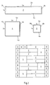
- Fig. 1 is a first embodiment of a Floor system according to the invention shown.
- the 1 are two different panels 2 and 4 shown.
- FIG. 1 therefore represents a floor system with a plurality of rectangular panels 2 and 4, the panels 2 and 4 on the side edges 2a, 2b du 4a, 4b Have connecting means, the tongue and groove connection are trained. Each on two opposite Side edges 2a and 2b or 4a and 4b are mutually corresponding connecting means in the form of groove and Spring trained. These are shown schematically in FIG. 1 are indicated and are further exemplified with reference to FIG. 4 explained below.
- the lengths of the side edges 2a, 2b correspond and 4a, 4b of panels 2 and 4 each an integer Multiples of a basic length "x".
- the in the unit of length "x" different lengths of the side edges are for the panels 2 on the side edges 2a 5x and on the Side edges 2b 1x on the one hand and for the panels 4 on the Side edges 4a and 4b each 2x on the other.
- 1 therefore has two Panel types with different panels 2 and 4, the different lengths on both pairs of side edges 2a and 2b and equal lengths on the side edges 4a and 4b have, but between the two panels 2 and 4 are different.
- Fig. 2 shows a further embodiment of a Floor system according to the invention
- the two panels 2 and 4 and a further panels 6 comprises the Side edges 6a and 6b with a length of 1x each exhibit.
- the different panels 2, 4 and 6 different lengths on at least one pair of Side edges.
- Part of the laying pattern corresponds to that in FIG. 1 installation pattern shown.
- Panels 6 have been added to this pattern.
- FIG. 3 shows a large-area laying pattern, in which a total of five different panels Dimensions have been used.
- the panels 14 and 14 'differed in their differently designed surfaces here have different shades.
- Fig. 3 shows panels 14 '' with the Readable characters are attached to the top. This allows words to be incorporated into a laying pattern for example in public buildings Show instructions or signposts.
- Fig. 4 shows an embodiment of a tongue and groove connection with locking connectors in shape a mechanically locking double tongue and groove connection.
- FIG. 4 shows a first panel 101 with a first Top 103 and a bottom 107.
- the profile along the first side edge 105 of the panels 101 has an upper Lip 131 and a lower lip 133 on between them form a groove 135. It is also above the upper one Lip 131 and the side edge 105 have a recess 140 intended.
- the profile of the second side edge 106 of the panels 102 is to the previously described profile of the first side edge 105 the panels 101 adapted. This is a top advantage 130 and a spring 132 provided between them also form a groove 137.
- Fig. 4 shows the two panels 101 and 102 in mechanical engagement with each other.
- the tops 103 and 104 adjoin one another at their side edges 105 and 106 and form an almost closed top in essentially without a routing groove or one Laying gap.
- That of the upper protrusion 130 and the spring 132 enclosed groove 137 in the profile of the second panel 102 takes the upper lip 131 of the profile of the first panels 101 on.
- the upper recess 140 takes the upper one Projection 130 on.
- that takes from the upper lip 131 and the lower lip 133 formed groove 135 the spring 132 on.
- the two profiles described above are laid in the following way.
- the second panel 102 is on their intended position and the first panels 101 in the direction perpendicular to the side edges 105 and 106 Panels 102 shifted until a firm resistance is noticeable.
- the on the edge opposite the first side edge 105 the first panels 101 is applied by means of impact force engaged the two profiles.
- the laying can also be done in reverse, by in the starting position the first panels 101 are attached to their predetermined position and the second panels 102 is moved relative to it until a firm resistance is felt is. The tapping block then becomes the second Side edge 106 created opposite side edge.
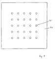
- 5 to 7 are embodiments for in Panels integrated lighting elements shown in in will be described below.
- Fig. 5 shows a panel 2 in cross section with a integrated lighting element 50.
- the lighting element 50 has an upper at least partially transparent cover 52, an adjacent upper housing part 54 a lower housing 56 and a light source 58 for Illuminate the cover 52 on. Together they form Cover 52, the housing part 54, the housing 56 and the Light source 58, the lighting element 50, which in one with the Panel 2 connected mounting frame 60 are used can. So with the help of the mounting frame 60 Luminous element 50 connected to the panel 2, so that the Integration in the flooring system described above Panels 2 is realized. In other words, the Panels 2 is the support of the lighting element 50 and connects and integrates this with the others Panels of the floor system.
- the lighting element 50 described above is concerned thus a flat light source, in the Cover symbols, letters, numbers or other patterns can be brought in for clues or information to convey.
- a lighting element 50 ' in which several punctiform light sources are integrated. These point individual smaller covers 52 'on an upper Housing part 54 'are integrated, the corresponding Has recesses.
- a housing 56 provided that the lighting element 50 'downwards concludes.
- the lighting element 50 ' is like the light element 50 in a mounting frame 60th used, which is firmly connected to the panel 2.
- the cables can be in between the panel edges on the bottom forming columns can be arranged.
- Such one Gap can be clearly seen, for example, in FIG. 4.
- the lighting elements 50 and 50 ' are installed preferably after laying the panels of the Floor system by the lighting element 50 or 50 'in the Installation frame 60 inserted and connected to the power supply is connected.
- the cables required for this will be before laying the panels on the sub-floor and if necessary fastened so that the panels are laid on it can be.
- the panels are usually made with one elastic insulating underlay mat that laid either designed separately or already with the factory Panels is connected. In this elastic underlay mat the cables can either be from above or from below press in, so that no unevenness in the laid Panels appear.
- the lighting elements 50, 50 ' also from below with an elastic layer, made of silicone, for example. This can avoid that the lighting elements are pushed through with a mechanical load and the associated Movements are permanently prevented.
Abstract
Description
Die Erfindung betrifft ein Fußbodensystem mit einer Mehrzahl von Paneelen, wobei die Paneelen an den Seitenkanten Verbindungsmittel aufweisen und wobei jeweils an zwei gegenüber angeordneten Seitenkanten zueinander korrespondierende Verbindungsmittel vorgesehen sind.The invention relates to a floor system with a Plurality of panels, the panels on the Have side edges connecting means and where each on two opposite side edges corresponding connecting means are provided.
Derartige Fußbodensysteme sind seit langer Zeit aus dem Stand der Technik bekannt. Insbesondere im Bereich der Laminatfußböden sind in den letzten Jahren Entwicklungen erfolgt, die durch die erreichte Qualität der Kernstrukturen aus mitteldichten Faserplatten (MDF) und hochdichten Fasernplatten (HDF) erst möglich geworden sind. Insbesondere die leimlos zu verlegenden Laminatpaneelen haben sich weit im Markt verbreitet, da diese Paneele mit wenigen Hilfsmitteln leicht verlegt werden können. Dabei dienen mechanische Verriegelungsmittel einem ausschließlich mechanischen Verbinden durch form- oder kraftschlüssige Verriegelungen, die ohne den Einsatz eines Klebstoffes eine zuverlässige Verbindung zwischen den Paneelen ermöglichen. Dabei gibt es eine Vielzahl von im Stand der Technik offenbarten Ausführungsformen und Methoden, die Paneelen zu verlegen.Such floor systems have long been out of the State of the art known. Especially in the area of Laminate floors have been evolving in recent years done by the quality achieved Core structures made of medium density fibreboard (MDF) and high-density fiberboard (HDF) have only become possible. In particular the glue-free laminate panels have spread widely in the market because these panels come with few tools can be easily installed. there mechanical locking means only serve one mechanical connection through positive or non-positive Interlocks that one without the use of an adhesive enable reliable connection between the panels. There are a large number of them in the prior art disclosed embodiments and methods of paneling embarrassed.
Beispielhaft wird auf die beiden Druckschriften WO 01/66875 und WO 01/66876 mit weiteren Nachweisen des Standes der Technik verwiesen. An example is the two publications WO 01/66875 and WO 01/66876 with further evidence of the status of Technology referred.
Die bisher bekannten Paneelen dienen dazu, den Fußboden von Räumen mit gleichmäßigen Verlegemustern auszulegen, wobei die eingesetzten Paneelen jeweils die gleichen Abmessungen aufweisen. Somit können an jeder Stelle innerhalb der auszulegenden Fläche die gleichen Paneelen eingesetzt werden, um die einheitliche Oberfläche zu erstellen.The panels known so far serve to cover the floor of To design rooms with uniform laying patterns, whereby the panels used have the same dimensions exhibit. Thus, at any point within the the same panels are used to create the unified interface.
Darüber hinaus ist es auch bekannt, Paneele mit gleichen Abmessungen, aber mit unterschiedlichen Dekoren zu verwenden, um abwechselnde Muster zu verlegen. Jedoch sind die somit erzeugten Muster in ihrer Variabilität begrenzt, da die Paneelen immer gleiche Abmessungen aufweisen.In addition, it is also known to use panels with the same Dimensions, but with different decors too use to lay alternate patterns. However are the variability of the resulting patterns is limited, because the panels always have the same dimensions.
Der Erfindung liegt daher das technische Problem zugrunde, ein Fußbodensystem anzugeben, bei dem die eingesetzten Paneelen eine größere Vielfalt des erzeugten Verlegemusters ermöglichen.The invention is therefore based on the technical problem specify a flooring system in which the used Panels a greater variety of the laying pattern produced enable.
Das zuvor aufgezeigte technische Problem wird
erfindungsgemäß durch ein Fußbodensystem mit den Merkmalen
des Anspruches 1 dadurch gelöst, daß die Längen der
Seitenkanten der Paneelen jeweils einem ganzzahligen
Vielfachen einer Grundlänge entsprechen und daß mindestens
zwei Paneelentypen mit unterschiedlichen Paneelen
vorgesehen sind, wobei die unterschiedlichen Paneelen
verschiedene Längen an zumindest einem Paar von
Seitenkanten aufweisen.The technical problem outlined above will
according to the invention by a floor system with the features
of
Die Erfindung wird im folgenden hauptsächlich anhand von rechteckigen Paneelen dargestellt, jedoch ist die Erfindung nicht darauf beschränkt. Es sind ebenfalls mehreckige miteinander zu einem Muster verbindbare Paneelen geeignet, die Erfindung zu realisieren.The invention is mainly based on rectangular panels are shown, however, the invention not limited to that. They are also polygonal suitable panels that can be connected to each other in a pattern, to implement the invention.
Erfindungsgemäß ist daher erkannt worden, daß allein durch eine größere Variabilität der Abmessungen der Paneelen ein Verlegemuster erzeugt werden kann, das sich in besonderer Weise von den bisher im Stand der Technik erreichbaren Mustern unterscheidet. Mit dem erfindungsgemäßen Fußbodensystem können regelmäßige und unregelmäßige Verlegemuster durch die unterschiedlichen Seitenkantenlängen erzeugt werden, die so nur in sehr aufwendiger Form durch separates Zurechtschneiden der aus dem Stand der Technik bekannten Paneelen hergestellt werden konnte.According to the invention it has therefore been recognized that only by a greater variability in the dimensions of the panels Laying patterns can be generated that are special Way of those previously achievable in the prior art Patterns differs. With the invention Floor system can be regular and irregular Laying pattern through the different Side edge lengths are generated that are only in very complex shape by cutting the panels known in the art are manufactured could.
In besonders bevorzugter Weise weisen die unterschiedlichen Paneelen verschiedene Längen an beiden Paaren von Seitenkanten auf. Somit unterscheiden sich die beiden unterschiedlichen Paneelentypen in ihrer Form erheblich, so daß sich allein aus dem Verlegemuster die Variabilität ergibt. An keinen der beiden zur Verfügung stehenden Seitenkantenpaare besteht eine Übereinstimmung in den Abmessungen.In a particularly preferred manner, the different ones Panels of different lengths on both pairs of Side edges. So the two differ different types of panels in their form considerably, so that variability arises solely from the laying pattern results. None of the two available There is a match in the side edge pairs in the Dimensions.
Weitere bevorzugte Ausführungsformen der vorliegenden Erfindung bestehen darin, die Anzahl der verschiedenen Paneelentypen größer als zwei zu wählen. Je größer die Anzahl ist, desto variabler werden die Gestaltungsmöglichkeiten beim Verlegen der Paneelen. Further preferred embodiments of the present Invention is the number of different Choose panel types larger than two. The bigger the Number, the more variable they become Design options when laying the panels.
Eine Weiterentwicklung der vorliegenden Erfindung besteht darin, daß die mindestens zwei verschiedenen Paneelentypen Paneelen mit unterschiedlich ausgestalteten Oberseiten aufweisen. Somit wird der optische Eindruck der Variabilität der unterschiedlichen Paneelentypen stärker hervorgehoben. Das Aussehen des verlegten Fußbodensystems kann fast beliebig gewählt werden.A further development of the present invention exists in that the at least two different types of panels Panels with differently designed tops exhibit. Thus, the visual impression of the Variability of the different panel types stronger highlighted. The appearance of the installed flooring system can be chosen almost arbitrarily.
In weiter bevorzugter Weise ist mindestens ein Paneelentyp mit auf den Oberseiten angebrachten lesbaren Zeichen versehen. Dadurch ist es möglich, in einem ersten Verlegemuster, das beispielsweise aus Paneelen eines Paneelentyps besteht, ein weiteres Verlegemuster einzubinden, das eine Beschriftung darstellt. Dieses Fußbodensystem kann insbesondere in öffentlichen Gebäuden eingesetzt werden, wobei auf dem Fußboden Hinweise und Wegweiser eingebracht werden können.In a further preferred manner, at least one type of panel is with legible signs on the top Mistake. This makes it possible in a first Laying pattern, which for example consists of a panel Panel type, another installation pattern to include, which is a label. This Flooring system can be particularly useful in public buildings are used, notes on the floor and Signposts can be introduced.
Wie bereits eingangs der Beschreibung erläutert worden ist, sind Paneelen mit Verbindungsmitteln bekannt, die als mechanisch verriegelnde Nut-Feder-Verbindungen ausgebildet sind. Somit kann das Fußbodensystem verlegt werden, ohne daß die Paneelen miteinander dauerhaft verbunden werden.As has already been explained at the beginning of the description, panels with connecting means are known as mechanically locking tongue and groove connections are. The floor system can thus be installed without that the panels are permanently connected to each other.
Daneben ist es selbstverständlich möglich, daß die Verbindungsmittel als zu verleimende Nut-Feder-Verbindungen ausgebildet sind. Diese herkömmliche Verlegeweise kann also genauso eingesetzt werden, wie die zuvor beschriebene mechanische Verriegelung.In addition, it is of course possible that the Lanyards as tongue and groove connections to be glued are trained. This conventional method of laying can can be used exactly as the one previously described mechanical locking.
Bei einer weiteren Ausgestaltung der vorliegenden Erfindung, die an sich unabhängig von den zuvor beschriebenen Ausführungsformen ist und daher auch separat beansprucht werden kann, besteht in der Integration von Leuchtmitteln in mindestens einer der Paneelen des Fußbodensystems. Somit können ein oder mehrere Lichtquellen in den Fußboden integriert werden, die als Hinweise Informationen vermitteln oder rein als gestalterische Elemente eingesetzt werden. Das Erscheinungsbild gerade von großflächigen Böden in Geschäften und Bürogebäuden kann somit individuell und je nach Bedarf gestaltet werden. In Kombination mit dem zuvor beschriebenen System von Paneelen mit unterschiedlichen variablen Abmessungen wird das Fußbodensystem daher weiter in vorteilhafter Weise verbessert.In a further embodiment of the present Invention, in itself, independent of the previous ones described embodiments is and therefore also separately can be claimed consists of the integration of Illuminants in at least one of the panels of the Floor system. Thus one or more light sources to be integrated into the floor as indications Communicate information or purely as design Elements are used. The appearance of large floors in shops and office buildings can be designed individually and as required. In Combination with the system of panels described above with different variable dimensions Floor system therefore further advantageously improved.
Bevorzugt ist, dass das Leuchtelement mindestens eine punktförmige Leuchtquelle und/oder mindestens eine flächige Leuchtquelle aufweist. Die punktförmigen Leuchtquellen sind weiter bevorzugt als Leuchtdioden ausgebildet, während die flächigen Leuchtquellen mit Leuchtdioden ausgeleuchtet werden. Mehrere punktformige Leuchtquellen können als Muster angeordnet werden, aus dem sich entweder Informationen als Buchstaben, Zahlen oder Piktogramme ableiten lassen oder das als rein gestalterische Element wirkt.It is preferred that the lighting element has at least one punctiform light source and / or at least one flat Has light source. The punctiform light sources are further preferably designed as LEDs, while the flat light sources illuminated with light-emitting diodes become. Several point-shaped light sources can be used as Patterns can be arranged from which either Information as letters, numbers or pictograms can be derived or as a purely design element acts.
Weiterhin ist es bevorzugt, dass die mindestens eine Paneele einen Einbaurahmen zur Aufnahme des Leuchtelementes aufweist. Dieser Einbaurahmen ist mit der Paneele verbunden, indem eine entsprechende Aussparung in der Paneele eingebracht wird, in die wiederum der Einbaurahmen einfach und schnell eingebaut werden kann. Somit kann eine Standardisierung für den Einbau verschiedenen Leuchtelemente geschaffen werden, die auch für einen nachträglichen Umbau oder Ersatz von Leuchtelementen genutzt werden kann.It is further preferred that the at least one Panels an installation frame for receiving the light element having. This mounting frame is with the panels connected by a corresponding recess in the Panels are inserted, in turn the mounting frame can be installed easily and quickly. Thus a Standardization for the installation of various Illuminated elements are created that also for one subsequent conversion or replacement of lighting elements can be used.
Die vorliegende Erfindung wird im folgenden anhand von Ausführungsbeispielen näher erläutert, wobei auf die beigefügte Zeichnung Bezug genommen wird. In der Zeichnung zeigen
- Fig. 1
- ein erstes Ausführungsbeispiel eines erfindungsgemäßen Fußbodensystems,
- Fig. 2
- ein zweites Ausführungsbeispiel eines erfindungsgemäßen Fußbodensystems,
- Fig. 3
- ein drittes Ausführungsbeispiel eines erfindungsgemäßen Fußbodensystems,
- Fig. 4
- ein Ausführungsbeispiel von mechanisch verriegelnden Verbindungsmitteln in Form einer Doppel-Nut-Feder-Verbindung,
- Fig. 5
- eine Paneele im Querschnitt mit einem ersten Leuchtelement,
- Fig. 6
- eine Paneele im Querschnitt mit einem zweiten Leuchtelement und
- Fig. 7
- eine Draufsicht des zweiten Leuchtelements.
- Fig. 1
- a first embodiment of a floor system according to the invention,
- Fig. 2
- a second embodiment of a floor system according to the invention,
- Fig. 3
- a third embodiment of a floor system according to the invention,
- Fig. 4
- an embodiment of mechanically locking connecting means in the form of a double tongue and groove connection,
- Fig. 5
- a panel in cross section with a first lighting element,
- Fig. 6
- a panels in cross section with a second lighting element and
- Fig. 7
- a plan view of the second lighting element.
In Fig. 1 ist ein erstes Ausführungsbeispiel eines
erfindungsgemäßen Fußbodensystems dargestellt. In der
oberen Hälfte der Fig. 1 sind zwei verschiedene Paneele 2
und 4 gezeigt. In der unteren Hälfte der Fig. 1 ist ein
Verlegemuster im halben Maßstab dargestellt, das die
verlegten Paneele 2 und 4 wiedergibt. Diese sind im
einzelnen gekennzeichnet.In Fig. 1 is a first embodiment of a
Floor system according to the invention shown. In the
1 are two
Fig. 1 stellt also ein Fußbodensystem mit einer Mehrzahl
von rechteckigen Paneelen 2 und 4 dar, wobei die Paneelen 2
und 4 an den Seitenkanten 2a, 2b du 4a, 4b
Verbindungsmittel aufweisen, die als Nut-Feder-verbindung
ausgebildet sind. Jeweils an zwei gegenüber angeordneten
Seitenkanten 2a und 2b bzw. 4a und 4b sind zueinander
korrespondierende Verbindungsmittel in Form von Nut und
Feder ausgebildet. Diese sind schematisch in Fig. 1
angedeutet und werden beispielhaft anhand von Fig. 4 weiter
untern erläutert.1 therefore represents a floor system with a plurality
of
Weiterhin entsprechen die Längen der Seitenkanten 2a, 2b
und 4a, 4b der Paneelen 2 und 4 jeweils einem ganzzahligen
Vielfachen einer Grundlänge "x". Die in der Längeneinheit
"x" unterschiedliche Längen der Seitenkanten betragen für
die Paneele 2 an den Seitenkanten 2a 5x und an den
Seitenkanten 2b 1x einerseits und für die Paneele 4 an den
Seitenkanten 4a und 4b jeweils 2x andererseits.Furthermore, the lengths of the
Das Fußbodensystem gemäß Fig. 1 weist also zwei
Paneelentypen mit unterschiedlichen Paneelen 2 und 4 auf,
die verschiedene Längen an beiden Paaren von Seitenkanten
2a und 2b und gleiche Längen an den Seitenkanten 4a und 4b
aufweisen, die aber zwischen beiden Paneelen 2 und 4
unterschiedlich sind. 1 therefore has two
Panel types with
In der unteren Hälfte der Fig. 1 ist ein Verlegemuster aus
Paneelen 2 und 4 dargestellt. Dieses Muster läßt sich
aufgrund der erfindungsgemäßen Ausgestaltung der Paneelen 2
und 4 sehr einfach realisieren. Die jeweils zu verbindenden
Seitenkanten der Paneelen 2 und 4 weisen zueinander
korrespondierende Verbindungsmittel auf.In the lower half of FIG. 1, an installation pattern is made
Fig. 2 zeigt ein weiteres Ausführungsbeispiel eines
erfindungsgemäßen Fußbodensystems, das die beiden Paneelen
2 und 4 sowie eine weitere Paneele 6 umfaßt, die
Seitenkanten 6a und 6b mit einer Länge von jeweils 1x
aufweisen. Somit weisen die unterschiedlichen Paneelen 2, 4
und 6 verschiedene Längen an zumindest einem Paar von
Seitenkanten auf.Fig. 2 shows a further embodiment of a
Floor system according to the invention, the two
Das in der unteren Hälfte der Fig. 2 dargestellte
Verlegemuster entspricht zu einem Teil dem in Fig. 1
dargestellten Verlegemuster. Zusätzlich dazu sind mehrere
Paneelen 6 diesem Muster hinzugefügt worden.That shown in the lower half of FIG. 2
Part of the laying pattern corresponds to that in FIG. 1
installation pattern shown. In addition, there are
In Fig. 3 ist ein großflächiges Verlegemuster dargestellt, in dem insgesamt Paneelen mit fünf verschiedenen Abmessungen verwendet worden sind.3 shows a large-area laying pattern, in which a total of five different panels Dimensions have been used.
Es sind dieses
Die Paneelen 14 und 14' unterschieden sich in ihrer
unterschiedlich ausgestalteten Oberflächen, die hier
unterschiedliche Farbtöne aufweisen.The
Darüber hinaus zeigt Fig. 3 Paneelen 14'', die mit auf den Oberseiten angebrachten lesbaren Zeichen versehen sind. Dadurch können in einem Verlegemuster Wörter eingearbeitet werden, die beispielsweise in öffentlichen Gebäuden Hinweise oder Wegweiser darstellen.In addition, Fig. 3 shows panels 14 '' with the Readable characters are attached to the top. This allows words to be incorporated into a laying pattern for example in public buildings Show instructions or signposts.
Fig. 4 zeigt ein Ausführungsbeispiel einer Nut-Feder-Verbindung mit verrastenden Verbindungsmitteln in Form einer mechanisch verriegelnde Doppel-Nut-Feder-Verbindung.Fig. 4 shows an embodiment of a tongue and groove connection with locking connectors in shape a mechanically locking double tongue and groove connection.
Fig. 4 zeigt eine erste Paneele 101 mit einer ersten
Oberseite 103 und einer Unterseite 107. Das Profil entlang
der ersten Seitenkante 105 der Paneele 101 weist eine obere
Lippe 131 und eine untere Lippe 133 auf, die zwischen sich
eine Nut 135 ausbilden. Weiterhin ist oberhalb der oberen
Lippe 131 und der Seitenkante 105 eine Ausnehmung 140
vorgesehen.4 shows a
Das Profil der zweiten Seitenkante 106 der Paneele 102 ist
an das zuvor beschriebene Profil der ersten Seitenkante 105
der Paneele 101 angepaßt. Dazu sind ein oberer Vorsprung
130 und eine Feder 132 vorgesehen, die zwischen sich
ebenfalls eine Nut 137 ausbilden.The profile of the second side edge 106 of the
Die Fig. 4 zeigt die beiden Paneelen 101 und 102 im
mechanischen Eingriff miteinander. Die Oberseiten 103 und
104 grenzen an ihren Seitenkanten 105 und 106 aneinander an
und bilden eine nahezu geschlossene Oberseite im
wesentlichen ohne eine Verlegungsnut oder einen
Verlegungsspalt.Fig. 4 shows the two
Die vom oberen Vorsprung 130 und der Feder 132
umschlossene Nut 137 im Profil der zweiten Paneele 102
nimmt die obere Lippe 131 des Profils der ersten Paneele
101 auf. Dazu nimmt die obere Ausnehmung 140 den oberen
Vorsprung 130 auf. Ebenso nimmt die von der oberen Lippe
131 und der unteren Lippe 133 gebildete Nut 135 die Feder
132 auf.That of the
Weiterhin ist ein an der Feder 132 ausgebildetes
Verriegelungselement 134 in einer in der unteren Lippe 133
ausgebildete Verriegelungsnut 139 angeordnet. Mittels
dieses Verriegelungsmechanismus wird einerseits ein
horizontales Auseinanderrutschen der beiden Paneele 101 und
102 verhindert und andererseits wird ein genaues Justieren
der beiden Paneelen 101 und 102 in ihrer vertikalen
Position zueinander erreicht.Furthermore, one is formed on the
Das Verlegen der beiden zuvor beschriebenen Profile erfolgt
in folgender Weise. Die zweite Paneele 102 befindet sich an
ihrer vorgesehenen Position und die erste Paneele 101 wird
in zu den Seitenkanten 105 und 106 senkrechter Richtung zur
Paneele 102 hin verschoben, bis ein fester Widerstand
spürbar ist. Danach werden mittels eines Schlagklotzes, der
auf der der ersten Seitenkante 105 gegenüberliegenden Kante
der ersten Paneele 101 angelegt wird, mittels Schlagkraft
die beiden Profile in Eingriff gebracht.The two profiles described above are laid
in the following way. The
Daneben kann das Verlegung auch umgekehrt erfolgen, indem
in der Ausgangsposition die erste Paneele 101 sich an ihrer
vorgegebenen Position befindet und die zweite Paneele 102
relativ dazu bewegt wird, bis ein fester Widerstand spürbar
ist. Der Schlagklotz wird dann an der der zweiten
Seitenkante 106 gegenüberliegenden Seitenkante angelegt.In addition, the laying can also be done in reverse, by
in the starting position the
In den Fig. 5 bis 7 sind Ausführungsbeispiele für in die Paneelen integrierte Leuchtelemente dargestellt, in im folgenden beschreiben werden.5 to 7 are embodiments for in Panels integrated lighting elements shown in in will be described below.
Fig. 5 zeigt eine Paneele 2 im Querschnitt mit einem
integrierten Leuchtelement 50. Das Leuchtelement 50 weist
eine obere zumindest teilweise transparente Abdeckung 52,
einen daran angrenzenden oberen Gehäuseteil 54 einem
unteren Gehäuse 56 sowie eine Lichtquelle 58 zum
Ausleuchten der Abdeckung 52 auf. Zusammen bilden die
Abdeckung 52, das Gehäuseteil 54, das Gehäuse 56 und die
Lichtquelle 58 das Leuchtelement 50, das in einen mit dem
Paneel 2 verbundenen Einbaurahmen 60 eingesetzt werden
kann. Mit Hilfe des Einbaurahmens 60 wird also das
Leuchtelement 50 mit dem Paneel 2 verbunden, so dass die
Integration in das beschriebene Fußbodensystem über die
Paneele 2 verwirklicht wird. Mit anderen Worten, die
Paneele 2 ist der Träger des Leuchtelementes 50 und
verbindet und integriert somit dieses mit den weiteren
Paneelen des Fußbodensystems.Fig. 5 shows a
Bei dem zuvor beschriebenen Leuchtelement 50 handelt es
sich somit um eine flächige Leuchtquelle, in deren
Abdeckung Symbole, Buchstaben, Zahlen oder andere Muster
eingebracht werden können, um Hinweise oder Informationen
zu vermitteln. The
Bei dem in Fig. 6 dargestellten Ausführungsbeispiel handelt
es sich um ein Leuchtelement 50', bei dem mehrere
punktförmige Leuchtquellen integriert sind. Diese weisen
einzelne kleinere Abdeckungen 52' auf, die in einem oberen
Gehäuseteil 54' integriert sind, das entsprechende
Aussparungen aufweist. Auch hier ist ein Gehäuse 56
vorgesehen, das das Leuchtelement 50' nach unten hin
abschließt. Weiterhin sind Lichtquellen 58' in Form von
Leuchtdioden oder kleinen Glühbirnen innerhalb des Gehäuses
56 angeordnet, die jeweils die Abdeckungen 52' von unten
ausleuchten. Es ist ebenso möglich, die Lichtquellen 58'
ohne Abdeckungen 52' nach oben sichtbar in dem
Leuchtelement zu integrieren. Auch das Leuchtelement 50'
wird wie das Leuchtelement 50 in einen Einbaurahmen 60
eingesetzt, der mit dem Paneel 2 fest verbunden ist.In the embodiment shown in Fig. 6 acts
it is a lighting element 50 ', in which several
punctiform light sources are integrated. These point
individual smaller covers 52 'on an upper
Housing part 54 'are integrated, the corresponding
Has recesses. Here too is a
Sollten die Paneelen direkt auf dem Untergrund verlegt werden, also ohne Unterlagsmatte, dann können die Kabel in den sich zwischen den Paneelenkanten an der Unterseite ausbildenden Spalten angeordnet werden. Ein derartiger Spalt ist beispielsweise in Fig. 4 deutlich zu erkennen.Should the panels be laid directly on the substrate without a mat, then the cables can be in between the panel edges on the bottom forming columns can be arranged. Such one Gap can be clearly seen, for example, in FIG. 4.
Der Einbau der Leuchtelemente 50 bzw. 50' erfolgt
vorzugsweise nach der Verlegung der Paneelen des
Fußbodensystems, indem das Leuchtelement 50 bzw. 50' in den
Einbaurahmen 60 eingesetzt und an die Stromversorgung
angeschlossen wird. Die dazu erforderlichen Kabel werden
vor der Verlegung der Paneelen auf dem Untergrund ausgelegt
und ggf. befestigt, so dass die Paneelen darauf verlegt
werden können. Die Paneelen werden in der Regel mit einer
elastischen isolierenden Unterlagsmatte verlegt, die
entweder separat ausgelegt oder bereits werkseitig mit den
Paneelen verbunden wird. In diese elastische Unterlagsmatte
können sich die Kabel entweder von oben oder von unten
eindrücken, so dass keine Unebenheiten bei den verlegten
Paneelen auftreten.The
Bei Bodenunebenheiten kann man die Leuchtelemente 50, 50'
von unten ebenfalls mit einer elastischen Schicht,
beispielsweise aus Silikon, versehen. Dadurch kann
vermieden werden, dass ein Durchdrücken der Leuchtelemente
bei einer mechanischen Belastung und die damit verbundenen
Bewegungen auf Dauer unterbunden werden.In the event of uneven floors, the
Claims (11)
dadurch gekennzeichnet, daß die unterschiedlichen Paneelen (2, 4; 6; 8, 10, 12, 14) verschiedene Längen an beiden Paaren von Seitenkanten (2a, 2b, 4a, 4b; 6a, 6b) aufweisen. Floor system according to claim 1,
characterized in that the different panels (2, 4; 6; 8, 10, 12, 14) have different lengths on both pairs of side edges (2a, 2b, 4a, 4b; 6a, 6b).
dadurch gekennzeichnet, daß die mindestens zwei verschiedenen Paneelentypen Paneelen mit unterschiedlich ausgestaltete Oberseiten aufweisen.Floor system according to claim 1 or 2,
characterized in that the at least two different types of panels have panels with differently configured upper sides.
dadurch gekennzeichnet, daß mindestens ein Paneelentyp mit auf den Oberseiten angebrachten lesbaren Zeichen versehen ist.Floor system according to claim 3,
characterized in that at least one type of panel is provided with legible characters affixed to the upper sides.
dadurch gekennzeichnet, daß die Verbindungsmittel als mechanisch verriegelnde Nut-Feder-Verbindungen ausgebildet sind.Floor system according to one of claims 1 to 4,
characterized in that the connecting means are designed as mechanically locking tongue and groove connections.
dadurch gekennzeichnet, daß die Verbindungsmittel als zu verleimende Nut-Feder-Verbindungen ausgebildet sind.Floor system according to one of claims 1 to 4,
characterized in that the connecting means are designed as tongue and groove connections to be glued.
dadurch gekennzeichnet, dass mindestens eine der Paneelen (2, 4; 6; 8, 10, 12, 14) mit mindestens einem integrierten Leuchtelement (50, 50') versehen ist.Floor system according to one of claims 1 to 6,
characterized in that at least one of the panels (2, 4; 6; 8, 10, 12, 14) is provided with at least one integrated lighting element (50, 50 ').
dadurch gekennzeichnet, dass das Leuchtelement (50, 50') mindestens eine flächige Leuchtquelle und/oder mindestens eine punktförmige Leuchtquelle aufweist. Floor system according to claim 7,
characterized in that the lighting element (50, 50 ') has at least one planar lighting source and / or at least one point-shaped lighting source.
dadurch gekennzeichnet, dass die flächige Leuchtquelle (58) mit Leuchtdioden ausgeleuchtet wird.Floor system according to claim 8,
characterized in that the planar light source (58) is illuminated with light-emitting diodes.
dadurch gekennzeichnet, dass die punktförmige Leuchtquelle (58') als Leuchtdiode ausgebildet ist.Floor system according to claim 8,
characterized in that the punctiform light source (58 ') is designed as a light-emitting diode.
dadurch gekennzeichnet, dass die mindestens eine Paneele (2, 4; 6; 8, 10, 12, 14) einen Einbaurahmen (60) zur Aufnahme des Leuchtelementes (50, 50') aufweist.Floor system according to one of claims 7 to 10,
characterized in that the at least one panel (2, 4; 6; 8, 10, 12, 14) has an installation frame (60) for receiving the lighting element (50, 50 ').
Applications Claiming Priority (2)
| Application Number | Priority Date | Filing Date | Title |
|---|---|---|---|
| DE10153233 | 2001-10-31 | ||
| DE10153233 | 2001-10-31 |
Publications (2)
| Publication Number | Publication Date |
|---|---|
| EP1308577A2 true EP1308577A2 (en) | 2003-05-07 |
| EP1308577A3 EP1308577A3 (en) | 2003-10-15 |
Family
ID=7704027
Family Applications (1)
| Application Number | Title | Priority Date | Filing Date |
|---|---|---|---|
| EP02024248A Withdrawn EP1308577A3 (en) | 2001-10-31 | 2002-10-31 | Flooring system with a plurality of panels |
Country Status (1)
| Country | Link |
|---|---|
| EP (1) | EP1308577A3 (en) |
Cited By (56)
| Publication number | Priority date | Publication date | Assignee | Title |
|---|---|---|---|---|
| EP1437456A1 (en) * | 2003-01-09 | 2004-07-14 | Flooring Industries Ltd. | Floor covering, floor panel and set of floor panels for forming such floor covering, and methods for packaging and manufacturing such floor panels |
| BE1015299A3 (en) * | 2003-01-09 | 2005-01-11 | Flooring Ind Ltd | Laminated flooring panels are packed in mixed lots of different lengths to assemble into a natural effect pattern |
| EP1585875A1 (en) * | 2002-12-09 | 2005-10-19 | Kronospan Technical Company Ltd. | Panels comprising a cable channel |
| DE102004015206A1 (en) * | 2004-03-29 | 2005-10-20 | Penrose Parkettgestaltung Gmbh | Parquet floor has a series of interlocking blocks of two or more different shapes marked with interface indicators |
| DE102004011531B3 (en) * | 2004-03-08 | 2005-11-03 | Kronotec Ag | Wood-based panel, in particular floor panel |
| EP1743988A2 (en) | 2005-07-12 | 2007-01-17 | Angelo Pessolano | Modular set of cladding elements |
| DE102005042644A1 (en) * | 2005-09-07 | 2007-03-08 | Guido Schulte | Floor panels has bearing plate with locking strips to enable panels to fasten together to form floor cover and cover plate stuck on top and decorative layer; floor cover thus formed |
| WO2007081254A1 (en) * | 2006-01-10 | 2007-07-19 | Välinge Innovation AB | Floor light |
| WO2008008016A1 (en) * | 2006-07-14 | 2008-01-17 | Välinge Innovation AB | Locking system comprising a combination lock for panels |
| US7721503B2 (en) | 2006-07-14 | 2010-05-25 | Valinge Innovation Ab | Locking system comprising a combination lock for panels |
| US7788871B2 (en) | 2001-09-20 | 2010-09-07 | Valinge Innovation Ab | Flooring and method for laying and manufacturing the same |
| US7802411B2 (en) | 2004-10-22 | 2010-09-28 | Valinge Innovation Ab | Mechanical locking system for floor panels |
| US7841145B2 (en) | 2004-10-22 | 2010-11-30 | Valinge Innovation Ab | Mechanical locking system for panels and method of installing same |
| US7841144B2 (en) | 2005-03-30 | 2010-11-30 | Valinge Innovation Ab | Mechanical locking system for panels and method of installing same |
| US7908815B2 (en) | 2006-07-11 | 2011-03-22 | Valinge Innovation Ab | Mechanical locking of floor panels with a flexible bristle tongue |
| ITUD20090168A1 (en) * | 2009-09-25 | 2011-03-26 | 3E Di Del Pin Fausto E Francesco Sn C | DOGHE DA PARQUET WITH A DRAWABLE AND WRITABLE LIGHTING SYSTEM, WITH EXTRACTABLE GRAPHICS IN RESIN SANDWICH. |
| US7930862B2 (en) | 2006-01-12 | 2011-04-26 | Valinge Innovation Ab | Floorboards having a resilent surface layer with a decorative groove |
| US8021014B2 (en) | 2006-01-10 | 2011-09-20 | Valinge Innovation Ab | Floor light |
| US8104244B2 (en) | 2002-04-22 | 2012-01-31 | Valinge Innovation Ab | Floorboards, flooring systems and method for manufacturing and installation thereof |
| US8112967B2 (en) | 2008-05-15 | 2012-02-14 | Valinge Innovation Ab | Mechanical locking of floor panels |
| US8353140B2 (en) | 2007-11-07 | 2013-01-15 | Valinge Innovation Ab | Mechanical locking of floor panels with vertical snap folding |
| US8499521B2 (en) | 2007-11-07 | 2013-08-06 | Valinge Innovation Ab | Mechanical locking of floor panels with vertical snap folding and an installation method to connect such panels |
| US8505257B2 (en) | 2008-01-31 | 2013-08-13 | Valinge Innovation Ab | Mechanical locking of floor panels |
| US8572922B2 (en) | 2011-07-05 | 2013-11-05 | Valinge Flooring Technology Ab | Mechanical locking of floor panels with a glued tongue |
| US8596013B2 (en) | 2012-04-04 | 2013-12-03 | Valinge Innovation Ab | Building panel with a mechanical locking system |
| US8627862B2 (en) | 2008-01-31 | 2014-01-14 | Valinge Innovation Ab | Mechanical locking of floor panels, methods to install and uninstall panels, a method and an equipment to produce the locking system, a method to connect a displaceable tongue to a panel and a tongue blank |
| US8650826B2 (en) | 2011-07-19 | 2014-02-18 | Valinge Flooring Technology Ab | Mechanical locking system for floor panels |
| US8713886B2 (en) | 2009-01-30 | 2014-05-06 | Valinge Innovation Ab | Mechanical lockings of floor panels and a tongue blank |
| US8763340B2 (en) | 2011-08-15 | 2014-07-01 | Valinge Flooring Technology Ab | Mechanical locking system for floor panels |
| US8769905B2 (en) | 2011-08-15 | 2014-07-08 | Valinge Flooring Technology Ab | Mechanical locking system for floor panels |
| US8826622B2 (en) | 2005-03-31 | 2014-09-09 | Flooring Industries Limited, Sarl | Floor panel having coupling parts allowing assembly with vertical motion |
| US8857126B2 (en) | 2011-08-15 | 2014-10-14 | Valinge Flooring Technology Ab | Mechanical locking system for floor panels |
| US8869485B2 (en) | 2006-12-08 | 2014-10-28 | Valinge Innovation Ab | Mechanical locking of floor panels |
| US8887468B2 (en) | 2011-05-06 | 2014-11-18 | Valinge Flooring Technology Ab | Mechanical locking system for building panels |
| US8991055B2 (en) | 2006-06-02 | 2015-03-31 | Flooring Industries Limited, Sarl | Floor covering, floor element and method for manufacturing floor elements |
| US9003735B2 (en) | 2010-04-15 | 2015-04-14 | Spanolux N.V.—Div. Balterio | Floor panel assembly |
| FR3019269A1 (en) * | 2014-03-28 | 2015-10-02 | Sovysols | LAMINATED LAMINAIRE COATING BLADE, LIGHT DEVICE AND USE THEREOF. |
| US9216541B2 (en) | 2012-04-04 | 2015-12-22 | Valinge Innovation Ab | Method for producing a mechanical locking system for building panels |
| US9255414B2 (en) | 2000-03-31 | 2016-02-09 | Pergo (Europe) Ab | Building panels |
| US9260870B2 (en) | 2014-03-24 | 2016-02-16 | Ivc N.V. | Set of mutually lockable panels |
| US9464443B2 (en) | 1998-10-06 | 2016-10-11 | Pergo (Europe) Ab | Flooring material comprising flooring elements which are assembled by means of separate flooring elements |
| US9464444B2 (en) | 2010-01-15 | 2016-10-11 | Pergo (Europe) Ab | Set of panels comprising retaining profiles with a separate clip and method for inserting the clip |
| US9593491B2 (en) | 2010-05-10 | 2017-03-14 | Pergo (Europe) Ab | Set of panels |
| US9725912B2 (en) | 2011-07-11 | 2017-08-08 | Ceraloc Innovation Ab | Mechanical locking system for floor panels |
| US10047527B2 (en) | 2009-09-04 | 2018-08-14 | Valinge Innovation Ab | Resilient floor |
| US10113318B2 (en) | 2005-03-31 | 2018-10-30 | Flooring Industries Limited, Sarl | Floor panel for forming and enhanced joint |
| US10280627B2 (en) | 2014-03-24 | 2019-05-07 | Flooring Industries Limited, Sarl | Set of mutually lockable panels |
| US10287777B2 (en) | 2016-09-30 | 2019-05-14 | Valinge Innovation Ab | Set of panels |
| US10301830B2 (en) | 2013-03-25 | 2019-05-28 | Valinge Innovation Ab | Floorboards provided with a mechanical locking system |
| US10316526B2 (en) | 2014-08-29 | 2019-06-11 | Valinge Innovation Ab | Vertical joint system for a surface covering panel |
| US10704269B2 (en) | 2010-01-11 | 2020-07-07 | Valinge Innovation Ab | Floor covering with interlocking design |
| US10738480B2 (en) | 2009-06-12 | 2020-08-11 | I4F Licensing Nv | Floor panel and floor covering consisting of a plurality of such floor panels |
| US10808410B2 (en) | 2018-01-09 | 2020-10-20 | Valinge Innovation Ab | Set of panels |
| US10837181B2 (en) | 2015-12-17 | 2020-11-17 | Valinge Innovation Ab | Method for producing a mechanical locking system for panels |
| US10947741B2 (en) | 2017-04-26 | 2021-03-16 | I4F Licensing Nv | Panel and covering |
| US11725395B2 (en) | 2009-09-04 | 2023-08-15 | Välinge Innovation AB | Resilient floor |
Citations (6)
| Publication number | Priority date | Publication date | Assignee | Title |
|---|---|---|---|---|
| US5095412A (en) * | 1990-03-27 | 1992-03-10 | William Leith | Illuminated floor panel |
| DE20000502U1 (en) * | 2000-01-13 | 2000-03-23 | Halemeier Gmbh & Co Kg | Lighting device for floors |
| WO2001002672A1 (en) * | 1999-07-05 | 2001-01-11 | Perstorp Flooring Ab | Floor element with guiding means |
| DE20004992U1 (en) * | 2000-03-17 | 2001-07-12 | Mayerhofer Gmbh | Flooring element |
| WO2001066876A1 (en) * | 2000-03-07 | 2001-09-13 | E.F.P. Floor Products Fussböden GmbH | Mechanical connection of panels |
| WO2001066877A1 (en) * | 2000-03-10 | 2001-09-13 | Perstorp Flooring Ab | Vertically joined floor elements comprising a combination of different floor elements |
-
2002
- 2002-10-31 EP EP02024248A patent/EP1308577A3/en not_active Withdrawn
Patent Citations (6)
| Publication number | Priority date | Publication date | Assignee | Title |
|---|---|---|---|---|
| US5095412A (en) * | 1990-03-27 | 1992-03-10 | William Leith | Illuminated floor panel |
| WO2001002672A1 (en) * | 1999-07-05 | 2001-01-11 | Perstorp Flooring Ab | Floor element with guiding means |
| DE20000502U1 (en) * | 2000-01-13 | 2000-03-23 | Halemeier Gmbh & Co Kg | Lighting device for floors |
| WO2001066876A1 (en) * | 2000-03-07 | 2001-09-13 | E.F.P. Floor Products Fussböden GmbH | Mechanical connection of panels |
| WO2001066877A1 (en) * | 2000-03-10 | 2001-09-13 | Perstorp Flooring Ab | Vertically joined floor elements comprising a combination of different floor elements |
| DE20004992U1 (en) * | 2000-03-17 | 2001-07-12 | Mayerhofer Gmbh | Flooring element |
Cited By (132)
| Publication number | Priority date | Publication date | Assignee | Title |
|---|---|---|---|---|
| US9464443B2 (en) | 1998-10-06 | 2016-10-11 | Pergo (Europe) Ab | Flooring material comprising flooring elements which are assembled by means of separate flooring elements |
| US9534397B2 (en) | 2000-03-31 | 2017-01-03 | Pergo (Europe) Ab | Flooring material |
| US9255414B2 (en) | 2000-03-31 | 2016-02-09 | Pergo (Europe) Ab | Building panels |
| US9677285B2 (en) | 2000-03-31 | 2017-06-13 | Pergo (Europe) Ab | Building panels |
| US9260869B2 (en) | 2000-03-31 | 2016-02-16 | Pergo (Europe) Ab | Building panels |
| US10233653B2 (en) | 2000-03-31 | 2019-03-19 | Pergo (Europe) Ab | Flooring material |
| US9611656B2 (en) | 2000-03-31 | 2017-04-04 | Pergo (Europe) Ab | Building panels |
| US9316006B2 (en) | 2000-03-31 | 2016-04-19 | Pergo (Europe) Ab | Building panels |
| US10156078B2 (en) | 2000-03-31 | 2018-12-18 | Pergo (Europe) Ab | Building panels |
| US10626619B2 (en) | 2000-03-31 | 2020-04-21 | Unilin Nordic Ab | Flooring material |
| US8250825B2 (en) | 2001-09-20 | 2012-08-28 | Välinge Innovation AB | Flooring and method for laying and manufacturing the same |
| US7788871B2 (en) | 2001-09-20 | 2010-09-07 | Valinge Innovation Ab | Flooring and method for laying and manufacturing the same |
| US8104244B2 (en) | 2002-04-22 | 2012-01-31 | Valinge Innovation Ab | Floorboards, flooring systems and method for manufacturing and installation thereof |
| US8359806B2 (en) | 2002-04-22 | 2013-01-29 | Valinge Innovation Ab | Floorboards, flooring systems and methods for manufacturing and installation thereof |
| EP1585875B1 (en) * | 2002-12-09 | 2006-10-04 | Kronospan Technical Company Ltd. | Construktion kit comprising panels of wood-based material and panels for the passage of cables or ducts |
| EP1585875A1 (en) * | 2002-12-09 | 2005-10-19 | Kronospan Technical Company Ltd. | Panels comprising a cable channel |
| US7591116B2 (en) | 2003-01-09 | 2009-09-22 | Flooring Industries Ltd Sarl | Floor covering, floor panel and set of floor panels for forming such floor covering, and methods for the packaging and manufacturing of such floor panels |
| BE1015299A3 (en) * | 2003-01-09 | 2005-01-11 | Flooring Ind Ltd | Laminated flooring panels are packed in mixed lots of different lengths to assemble into a natural effect pattern |
| EP1437456A1 (en) * | 2003-01-09 | 2004-07-14 | Flooring Industries Ltd. | Floor covering, floor panel and set of floor panels for forming such floor covering, and methods for packaging and manufacturing such floor panels |
| US7621093B2 (en) | 2003-01-09 | 2009-11-24 | Flooring Industries Ltd. | Floor covering, floor panel and set of floor panels for forming such floor covering and methods for the packaging and manufacturing of such floor panels |
| DE102004011531B3 (en) * | 2004-03-08 | 2005-11-03 | Kronotec Ag | Wood-based panel, in particular floor panel |
| DE102004011531C5 (en) * | 2004-03-08 | 2014-03-06 | Kronotec Ag | Wood-based panel, in particular floor panel |
| DE102004015206A1 (en) * | 2004-03-29 | 2005-10-20 | Penrose Parkettgestaltung Gmbh | Parquet floor has a series of interlocking blocks of two or more different shapes marked with interface indicators |
| US8042311B2 (en) | 2004-10-22 | 2011-10-25 | Valinge Innovation Ab | Mechanical locking system for panels and method of installing same |
| US8707650B2 (en) | 2004-10-22 | 2014-04-29 | Valinge Innovation Ab | Mechanical locking system for panels and method of installing same |
| US8528289B2 (en) | 2004-10-22 | 2013-09-10 | Valinge Innovation Ab | Mechanical locking system for floor panels |
| US8341915B2 (en) | 2004-10-22 | 2013-01-01 | Valinge Innovation Ab | Mechanical locking of floor panels with a flexible tongue |
| US7841145B2 (en) | 2004-10-22 | 2010-11-30 | Valinge Innovation Ab | Mechanical locking system for panels and method of installing same |
| US8381477B2 (en) | 2004-10-22 | 2013-02-26 | Valinge Innovation Ab | Mechanical locking of floor panels with a flexible tongue |
| US8640424B2 (en) | 2004-10-22 | 2014-02-04 | Valinge Innovation Ab | Mechanical locking system for floor panels |
| US7980041B2 (en) | 2004-10-22 | 2011-07-19 | Valinge Innovation Ab | Mechanical locking system for floor panels |
| US8181416B2 (en) | 2004-10-22 | 2012-05-22 | Valinge Innovation Ab | Mechanical locking system for floor panels |
| US7802411B2 (en) | 2004-10-22 | 2010-09-28 | Valinge Innovation Ab | Mechanical locking system for floor panels |
| US8079196B2 (en) | 2005-03-30 | 2011-12-20 | Valinge Innovation Ab | Mechanical locking system for panels |
| US8387327B2 (en) | 2005-03-30 | 2013-03-05 | Valinge Innovation Ab | Mechanical locking system for floor panels |
| US8677714B2 (en) | 2005-03-30 | 2014-03-25 | Valinge Innovation Ab | Mechanical locking system for panels and method of installing same |
| US7866110B2 (en) | 2005-03-30 | 2011-01-11 | Valinge Innovation Ab | Mechanical locking system for panels and method of installing same |
| US7841144B2 (en) | 2005-03-30 | 2010-11-30 | Valinge Innovation Ab | Mechanical locking system for panels and method of installing same |
| US8826622B2 (en) | 2005-03-31 | 2014-09-09 | Flooring Industries Limited, Sarl | Floor panel having coupling parts allowing assembly with vertical motion |
| US9212493B2 (en) | 2005-03-31 | 2015-12-15 | Flooring Industries Limited, Sarl | Methods for manufacturing and packaging floor panels, devices used thereby, as well as floor panel and packed set of floor panels |
| US10113318B2 (en) | 2005-03-31 | 2018-10-30 | Flooring Industries Limited, Sarl | Floor panel for forming and enhanced joint |
| EP1743988A3 (en) * | 2005-07-12 | 2008-10-22 | Angelo Pessolano | Modular set of cladding elements |
| EP1743988A2 (en) | 2005-07-12 | 2007-01-17 | Angelo Pessolano | Modular set of cladding elements |
| DE102005042644A1 (en) * | 2005-09-07 | 2007-03-08 | Guido Schulte | Floor panels has bearing plate with locking strips to enable panels to fasten together to form floor cover and cover plate stuck on top and decorative layer; floor cover thus formed |
| WO2007081254A1 (en) * | 2006-01-10 | 2007-07-19 | Välinge Innovation AB | Floor light |
| US8021014B2 (en) | 2006-01-10 | 2011-09-20 | Valinge Innovation Ab | Floor light |
| US8092036B2 (en) | 2006-01-11 | 2012-01-10 | Valinge Innovation Ab | Floor light |
| US8245478B2 (en) | 2006-01-12 | 2012-08-21 | Välinge Innovation AB | Set of floorboards with sealing arrangement |
| US8511031B2 (en) | 2006-01-12 | 2013-08-20 | Valinge Innovation Ab | Set F floorboards with overlapping edges |
| US7930862B2 (en) | 2006-01-12 | 2011-04-26 | Valinge Innovation Ab | Floorboards having a resilent surface layer with a decorative groove |
| US9145691B2 (en) | 2006-06-02 | 2015-09-29 | Flooring Industries Limited, Sarl | Floor covering of floor elements |
| US10125499B2 (en) | 2006-06-02 | 2018-11-13 | Flooring Industries Limited, Sarl | Floor covering, floor element and method for manufacturing floor elements |
| US9695599B2 (en) | 2006-06-02 | 2017-07-04 | Flooring Industries Limited, Sarl | Floor covering, floor element and method for manufacturing floor elements |
| US11933055B2 (en) | 2006-06-02 | 2024-03-19 | Unilin, Bv | Floor covering, floor element and method for manufacturing floor elements |
| US11680414B2 (en) | 2006-06-02 | 2023-06-20 | Flooring Industries Limited, Sarl | Floor covering, floor element and method for manufacturing floor elements |
| US9487957B2 (en) | 2006-06-02 | 2016-11-08 | Flooring Industries Limited, Sarl | Floor covering, floor element and method for manufacturing floor elements |
| US10975578B2 (en) | 2006-06-02 | 2021-04-13 | Flooring Industries Limited, Sarl | Floor covering, floor element and method for manufacturing floor elements |
| US10975579B2 (en) | 2006-06-02 | 2021-04-13 | Flooring Industries Limited, Sarl | Floor covering, floor element and method for manufacturing floor elements |
| US9890542B2 (en) | 2006-06-02 | 2018-02-13 | Flooring Industries Limited, Sarl | Floor covering, floor element and method for manufacturing floor elements |
| US9366037B2 (en) | 2006-06-02 | 2016-06-14 | Flooring Industries Limited, Sarl | Floor covering, floor element and method for manufacturing floor elements |
| US10745921B2 (en) | 2006-06-02 | 2020-08-18 | Flooring Industries Limited, Sarl | Floor covering, floor element and method for manufacturing floor elements |
| US9200460B2 (en) | 2006-06-02 | 2015-12-01 | Flooring Industries Limited, Sarl | Floor covering, floor element and method for manufacturing floor elements |
| US8991055B2 (en) | 2006-06-02 | 2015-03-31 | Flooring Industries Limited, Sarl | Floor covering, floor element and method for manufacturing floor elements |
| US10519674B2 (en) | 2006-06-02 | 2019-12-31 | Flooring Industries Limited, Sarl | Floor covering, floor element and method for manufacturing floor elements |
| US10358831B2 (en) | 2006-06-02 | 2019-07-23 | Flooring Industries Limited, Sarl | Floor covering, floor element and method for manufacturing floor elements |
| US8341914B2 (en) | 2006-07-11 | 2013-01-01 | Valinge Innovation Ab | Mechanical locking of floor panels with a flexible bristle tongue |
| US8033074B2 (en) | 2006-07-11 | 2011-10-11 | Valinge Innovation Ab | Mechanical locking of floor panels with a flexible bristle tongue |
| US8844236B2 (en) | 2006-07-11 | 2014-09-30 | Valinge Innovation Ab | Mechanical locking of floor panels with a flexible bristle tongue |
| US8359805B2 (en) | 2006-07-11 | 2013-01-29 | Valinge Innovation Ab | Mechanical locking of floor panels with a flexible bristle tongue |
| US7908815B2 (en) | 2006-07-11 | 2011-03-22 | Valinge Innovation Ab | Mechanical locking of floor panels with a flexible bristle tongue |
| US7861482B2 (en) | 2006-07-14 | 2011-01-04 | Valinge Innovation Ab | Locking system comprising a combination lock for panels |
| US7721503B2 (en) | 2006-07-14 | 2010-05-25 | Valinge Innovation Ab | Locking system comprising a combination lock for panels |
| WO2008008016A1 (en) * | 2006-07-14 | 2008-01-17 | Välinge Innovation AB | Locking system comprising a combination lock for panels |
| US8869485B2 (en) | 2006-12-08 | 2014-10-28 | Valinge Innovation Ab | Mechanical locking of floor panels |
| US8499521B2 (en) | 2007-11-07 | 2013-08-06 | Valinge Innovation Ab | Mechanical locking of floor panels with vertical snap folding and an installation method to connect such panels |
| US10214917B2 (en) | 2007-11-07 | 2019-02-26 | Valinge Innovation Ab | Mechanical locking of floor panels with vertical snap folding |
| US8353140B2 (en) | 2007-11-07 | 2013-01-15 | Valinge Innovation Ab | Mechanical locking of floor panels with vertical snap folding |
| US8544234B2 (en) | 2007-11-07 | 2013-10-01 | Valinge Innovation Ab | Mechanical locking of floor panels with vertical snap folding |
| US11519183B2 (en) | 2007-11-07 | 2022-12-06 | Valinge Innovation Ab | Mechanical locking of floor panels with vertical snap folding |
| US8505257B2 (en) | 2008-01-31 | 2013-08-13 | Valinge Innovation Ab | Mechanical locking of floor panels |
| US8627862B2 (en) | 2008-01-31 | 2014-01-14 | Valinge Innovation Ab | Mechanical locking of floor panels, methods to install and uninstall panels, a method and an equipment to produce the locking system, a method to connect a displaceable tongue to a panel and a tongue blank |
| US8448402B2 (en) | 2008-05-15 | 2013-05-28 | Välinge Innovation AB | Mechanical locking of building panels |
| US8925274B2 (en) | 2008-05-15 | 2015-01-06 | Valinge Innovation Ab | Mechanical locking of building panels |
| US8112967B2 (en) | 2008-05-15 | 2012-02-14 | Valinge Innovation Ab | Mechanical locking of floor panels |
| US8713886B2 (en) | 2009-01-30 | 2014-05-06 | Valinge Innovation Ab | Mechanical lockings of floor panels and a tongue blank |
| US10738481B2 (en) | 2009-06-12 | 2020-08-11 | I4F Licensing Nv | Floor panel and floor covering consisting of a plurality of such floor panels |
| US10738482B2 (en) | 2009-06-12 | 2020-08-11 | I4F Licensing Nv | Floor panel and floor covering consisting of a plurality of such floor panels |
| US10738480B2 (en) | 2009-06-12 | 2020-08-11 | I4F Licensing Nv | Floor panel and floor covering consisting of a plurality of such floor panels |
| US11725395B2 (en) | 2009-09-04 | 2023-08-15 | Välinge Innovation AB | Resilient floor |
| US11306486B2 (en) | 2009-09-04 | 2022-04-19 | Valinge Innovation Ab | Resilient floor |
| US10047527B2 (en) | 2009-09-04 | 2018-08-14 | Valinge Innovation Ab | Resilient floor |
| US10526793B2 (en) | 2009-09-04 | 2020-01-07 | Valinge Innovation Ab | Resilient floor |
| ITUD20090168A1 (en) * | 2009-09-25 | 2011-03-26 | 3E Di Del Pin Fausto E Francesco Sn C | DOGHE DA PARQUET WITH A DRAWABLE AND WRITABLE LIGHTING SYSTEM, WITH EXTRACTABLE GRAPHICS IN RESIN SANDWICH. |
| US11359387B2 (en) | 2010-01-11 | 2022-06-14 | Valinge Innovation Ab | Floor covering with interlocking design |
| US10704269B2 (en) | 2010-01-11 | 2020-07-07 | Valinge Innovation Ab | Floor covering with interlocking design |
| US11795701B2 (en) | 2010-01-11 | 2023-10-24 | Välinge Innovation AB | Floor covering with interlocking design |
| US9464444B2 (en) | 2010-01-15 | 2016-10-11 | Pergo (Europe) Ab | Set of panels comprising retaining profiles with a separate clip and method for inserting the clip |
| US9003735B2 (en) | 2010-04-15 | 2015-04-14 | Spanolux N.V.—Div. Balterio | Floor panel assembly |
| US9593491B2 (en) | 2010-05-10 | 2017-03-14 | Pergo (Europe) Ab | Set of panels |
| US11781577B2 (en) | 2011-05-06 | 2023-10-10 | Valinge Innovation Ab | Mechanical locking system for building panels |
| US8887468B2 (en) | 2011-05-06 | 2014-11-18 | Valinge Flooring Technology Ab | Mechanical locking system for building panels |
| US8572922B2 (en) | 2011-07-05 | 2013-11-05 | Valinge Flooring Technology Ab | Mechanical locking of floor panels with a glued tongue |
| US9856656B2 (en) | 2011-07-05 | 2018-01-02 | Ceraloc Innovation Ab | Mechanical locking of floor panels with a glued tongue |
| US8959866B2 (en) | 2011-07-05 | 2015-02-24 | Valinge Flooring Technology Ab | Mechanical locking of floor panels with a glued tongue |
| US9725912B2 (en) | 2011-07-11 | 2017-08-08 | Ceraloc Innovation Ab | Mechanical locking system for floor panels |
| US8650826B2 (en) | 2011-07-19 | 2014-02-18 | Valinge Flooring Technology Ab | Mechanical locking system for floor panels |
| US8769905B2 (en) | 2011-08-15 | 2014-07-08 | Valinge Flooring Technology Ab | Mechanical locking system for floor panels |
| US8857126B2 (en) | 2011-08-15 | 2014-10-14 | Valinge Flooring Technology Ab | Mechanical locking system for floor panels |
| US8763340B2 (en) | 2011-08-15 | 2014-07-01 | Valinge Flooring Technology Ab | Mechanical locking system for floor panels |
| US9216541B2 (en) | 2012-04-04 | 2015-12-22 | Valinge Innovation Ab | Method for producing a mechanical locking system for building panels |
| US8596013B2 (en) | 2012-04-04 | 2013-12-03 | Valinge Innovation Ab | Building panel with a mechanical locking system |
| US10407919B2 (en) | 2013-03-25 | 2019-09-10 | Valinge Innovation Ab | Floorboards provided with a mechanical locking system |
| US11898356B2 (en) | 2013-03-25 | 2024-02-13 | Välinge Innovation AB | Floorboards provided with a mechanical locking system |
| US10844612B2 (en) | 2013-03-25 | 2020-11-24 | Valinge Innovation Ab | Floorboards provided with a mechanical locking system |
| US10301830B2 (en) | 2013-03-25 | 2019-05-28 | Valinge Innovation Ab | Floorboards provided with a mechanical locking system |
| US11421426B2 (en) | 2013-03-25 | 2022-08-23 | Valinge Innovation Ab | Floorboards provided with a mechanical locking system |
| US9260870B2 (en) | 2014-03-24 | 2016-02-16 | Ivc N.V. | Set of mutually lockable panels |
| US10612250B2 (en) | 2014-03-24 | 2020-04-07 | Flooring Industries Limited, Sarl | Set of mutually lockable panels |
| US10280627B2 (en) | 2014-03-24 | 2019-05-07 | Flooring Industries Limited, Sarl | Set of mutually lockable panels |
| FR3019269A1 (en) * | 2014-03-28 | 2015-10-02 | Sovysols | LAMINATED LAMINAIRE COATING BLADE, LIGHT DEVICE AND USE THEREOF. |
| US10982449B2 (en) | 2014-08-29 | 2021-04-20 | Valinge Innovation Ab | Vertical joint system for a surface covering panel |
| US10316526B2 (en) | 2014-08-29 | 2019-06-11 | Valinge Innovation Ab | Vertical joint system for a surface covering panel |
| US11661749B2 (en) | 2014-08-29 | 2023-05-30 | Valinge Innovation Ab | Vertical joint system for a surface covering panel |
| US10865571B2 (en) | 2014-08-29 | 2020-12-15 | Valinge Innovation Ab | Vertical joint system for a surface covering panel |
| US10837181B2 (en) | 2015-12-17 | 2020-11-17 | Valinge Innovation Ab | Method for producing a mechanical locking system for panels |
| US10851549B2 (en) | 2016-09-30 | 2020-12-01 | Valinge Innovation Ab | Set of panels |
| US11814850B2 (en) | 2016-09-30 | 2023-11-14 | Välinge Innovation AB | Set of panels |
| US10287777B2 (en) | 2016-09-30 | 2019-05-14 | Valinge Innovation Ab | Set of panels |
| US11441319B2 (en) | 2017-04-26 | 2022-09-13 | I4F Licensing Nv | Panel and covering |
| US10947741B2 (en) | 2017-04-26 | 2021-03-16 | I4F Licensing Nv | Panel and covering |
| US11808045B2 (en) | 2018-01-09 | 2023-11-07 | Välinge Innovation AB | Set of panels |
| US10808410B2 (en) | 2018-01-09 | 2020-10-20 | Valinge Innovation Ab | Set of panels |
Also Published As
| Publication number | Publication date |
|---|---|
| EP1308577A3 (en) | 2003-10-15 |
Similar Documents
| Publication | Publication Date | Title |
|---|---|---|
| EP1308577A2 (en) | Flooring system with a plurality of panels | |
| DE3404813C2 (en) | Illuminable step edge profile | |
| EP1730366B1 (en) | Panel element for covering | |
| EP1725720B1 (en) | Panel element for covering | |
| EP1518032A1 (en) | Panel of a floor system, particularly a laminate floor | |
| DE602004011838T3 (en) | METHOD FOR PRODUCING A FLOOR PLATE | |
| DE2648843A1 (en) | LIGHT DIODE DISPLAY DEVICE FOR A MULTIPLE PUSH BUTTON ARRANGEMENT | |
| DE102010051003A1 (en) | Double floor construction | |
| EP3281253B1 (en) | Patchboard | |
| DE8531020U1 (en) | Kit for a cable rail | |
| EP1538276B1 (en) | Floor panel | |
| DE10313779A1 (en) | Tiling system for walls , floors and ceilings, uses first fixture pattern of saliencies for carrier elements, and second fixture pattern of recesses for tiles | |
| DE19815409C2 (en) | Arrangement for laying a floor covering, in particular floor slabs | |
| EP2177687B1 (en) | Assembly containing a number of panels | |
| EP1836361B1 (en) | Building component, in particular panel, and method for laying panels | |
| DE102017105153A1 (en) | Floorboard system | |
| EP0399957A2 (en) | Constructive element for the formation of message panels | |
| EP0033904A1 (en) | Metal clip for wall and ceiling coverings | |
| DE8328123U1 (en) | Holding device | |
| DE102008003117A1 (en) | Device for locking two building boards, particularly floor panels, has building board with lateral edge, and groove is provided in core of building board | |
| WO2013037460A1 (en) | Lighting device | |
| WO2006002818A1 (en) | Surface coating | |
| DE202019000120U1 (en) | Floor covering made of composite rectangular or square panels | |
| EP1783423B1 (en) | System for incorporation of a decorational element into the covering of a floor, wall, ceiling, or a similar structures as well as the covering itself | |
| DE19823357A1 (en) | Wall tile with spacers |
Legal Events
| Date | Code | Title | Description |
|---|---|---|---|
| PUAI | Public reference made under article 153(3) epc to a published international application that has entered the european phase |
Free format text: ORIGINAL CODE: 0009012 |
|
| AK | Designated contracting states |
Designated state(s): AT BE BG CH CY CZ DE DK EE ES FI FR GB GR IE IT LI LU MC NL PT SE SK TR |
|
| AX | Request for extension of the european patent |
Extension state: AL LT LV MK RO SI |
|
| PUAL | Search report despatched |
Free format text: ORIGINAL CODE: 0009013 |
|
| AK | Designated contracting states |
Kind code of ref document: A3 Designated state(s): AT BE BG CH CY CZ DE DK EE ES FI FR GB GR IE IT LI LU MC NL PT SE SK TR |
|
| AX | Request for extension of the european patent |
Extension state: AL LT LV MK RO SI |
|
| RIC1 | Information provided on ipc code assigned before grant |
Ipc: 7F 21V 33/00 B Ipc: 7E 04F 13/08 B Ipc: 7F 21S 8/02 B Ipc: 7E 04F 15/04 A |
|
| AKX | Designation fees paid | ||
| REG | Reference to a national code |
Ref country code: DE Ref legal event code: 8566 |
|
| STAA | Information on the status of an ep patent application or granted ep patent |
Free format text: STATUS: THE APPLICATION IS DEEMED TO BE WITHDRAWN |
|
| 18D | Application deemed to be withdrawn |
Effective date: 20040416 |