EP1308342A2 - An engine torque determination for a powertrain with torque converter - Google Patents
An engine torque determination for a powertrain with torque converter Download PDFInfo
- Publication number
- EP1308342A2 EP1308342A2 EP02102497A EP02102497A EP1308342A2 EP 1308342 A2 EP1308342 A2 EP 1308342A2 EP 02102497 A EP02102497 A EP 02102497A EP 02102497 A EP02102497 A EP 02102497A EP 1308342 A2 EP1308342 A2 EP 1308342A2
- Authority
- EP
- European Patent Office
- Prior art keywords
- torque
- engine
- speed
- determining
- torque converter
- Prior art date
- Legal status (The legal status is an assumption and is not a legal conclusion. Google has not performed a legal analysis and makes no representation as to the accuracy of the status listed.)
- Withdrawn
Links
Images


Classifications
-
- F—MECHANICAL ENGINEERING; LIGHTING; HEATING; WEAPONS; BLASTING
- F02—COMBUSTION ENGINES; HOT-GAS OR COMBUSTION-PRODUCT ENGINE PLANTS
- F02D—CONTROLLING COMBUSTION ENGINES
- F02D41/00—Electrical control of supply of combustible mixture or its constituents
- F02D41/02—Circuit arrangements for generating control signals
- F02D41/14—Introducing closed-loop corrections
- F02D41/1497—With detection of the mechanical response of the engine
-
- F—MECHANICAL ENGINEERING; LIGHTING; HEATING; WEAPONS; BLASTING
- F02—COMBUSTION ENGINES; HOT-GAS OR COMBUSTION-PRODUCT ENGINE PLANTS
- F02D—CONTROLLING COMBUSTION ENGINES
- F02D11/00—Arrangements for, or adaptations to, non-automatic engine control initiation means, e.g. operator initiated
- F02D11/06—Arrangements for, or adaptations to, non-automatic engine control initiation means, e.g. operator initiated characterised by non-mechanical control linkages, e.g. fluid control linkages or by control linkages with power drive or assistance
- F02D11/10—Arrangements for, or adaptations to, non-automatic engine control initiation means, e.g. operator initiated characterised by non-mechanical control linkages, e.g. fluid control linkages or by control linkages with power drive or assistance of the electric type
- F02D11/105—Arrangements for, or adaptations to, non-automatic engine control initiation means, e.g. operator initiated characterised by non-mechanical control linkages, e.g. fluid control linkages or by control linkages with power drive or assistance of the electric type characterised by the function converting demand to actuation, e.g. a map indicating relations between an accelerator pedal position and throttle valve opening or target engine torque
-
- F—MECHANICAL ENGINEERING; LIGHTING; HEATING; WEAPONS; BLASTING
- F02—COMBUSTION ENGINES; HOT-GAS OR COMBUSTION-PRODUCT ENGINE PLANTS
- F02D—CONTROLLING COMBUSTION ENGINES
- F02D31/00—Use of speed-sensing governors to control combustion engines, not otherwise provided for
- F02D31/001—Electric control of rotation speed
-
- F—MECHANICAL ENGINEERING; LIGHTING; HEATING; WEAPONS; BLASTING
- F02—COMBUSTION ENGINES; HOT-GAS OR COMBUSTION-PRODUCT ENGINE PLANTS
- F02D—CONTROLLING COMBUSTION ENGINES
- F02D37/00—Non-electrical conjoint control of two or more functions of engines, not otherwise provided for
- F02D37/02—Non-electrical conjoint control of two or more functions of engines, not otherwise provided for one of the functions being ignition
-
- B—PERFORMING OPERATIONS; TRANSPORTING
- B60—VEHICLES IN GENERAL
- B60W—CONJOINT CONTROL OF VEHICLE SUB-UNITS OF DIFFERENT TYPE OR DIFFERENT FUNCTION; CONTROL SYSTEMS SPECIALLY ADAPTED FOR HYBRID VEHICLES; ROAD VEHICLE DRIVE CONTROL SYSTEMS FOR PURPOSES NOT RELATED TO THE CONTROL OF A PARTICULAR SUB-UNIT
- B60W50/00—Details of control systems for road vehicle drive control not related to the control of a particular sub-unit, e.g. process diagnostic or vehicle driver interfaces
- B60W2050/0001—Details of the control system
- B60W2050/0019—Control system elements or transfer functions
- B60W2050/0022—Gains, weighting coefficients or weighting functions
-
- B—PERFORMING OPERATIONS; TRANSPORTING
- B60—VEHICLES IN GENERAL
- B60W—CONJOINT CONTROL OF VEHICLE SUB-UNITS OF DIFFERENT TYPE OR DIFFERENT FUNCTION; CONTROL SYSTEMS SPECIALLY ADAPTED FOR HYBRID VEHICLES; ROAD VEHICLE DRIVE CONTROL SYSTEMS FOR PURPOSES NOT RELATED TO THE CONTROL OF A PARTICULAR SUB-UNIT
- B60W2510/00—Input parameters relating to a particular sub-units
- B60W2510/06—Combustion engines, Gas turbines
- B60W2510/0638—Engine speed
-
- B—PERFORMING OPERATIONS; TRANSPORTING
- B60—VEHICLES IN GENERAL
- B60W—CONJOINT CONTROL OF VEHICLE SUB-UNITS OF DIFFERENT TYPE OR DIFFERENT FUNCTION; CONTROL SYSTEMS SPECIALLY ADAPTED FOR HYBRID VEHICLES; ROAD VEHICLE DRIVE CONTROL SYSTEMS FOR PURPOSES NOT RELATED TO THE CONTROL OF A PARTICULAR SUB-UNIT
- B60W2510/00—Input parameters relating to a particular sub-units
- B60W2510/06—Combustion engines, Gas turbines
- B60W2510/0695—Inertia
-
- B—PERFORMING OPERATIONS; TRANSPORTING
- B60—VEHICLES IN GENERAL
- B60W—CONJOINT CONTROL OF VEHICLE SUB-UNITS OF DIFFERENT TYPE OR DIFFERENT FUNCTION; CONTROL SYSTEMS SPECIALLY ADAPTED FOR HYBRID VEHICLES; ROAD VEHICLE DRIVE CONTROL SYSTEMS FOR PURPOSES NOT RELATED TO THE CONTROL OF A PARTICULAR SUB-UNIT
- B60W2510/00—Input parameters relating to a particular sub-units
- B60W2510/10—Change speed gearings
- B60W2510/1095—Inertia
-
- B—PERFORMING OPERATIONS; TRANSPORTING
- B60—VEHICLES IN GENERAL
- B60W—CONJOINT CONTROL OF VEHICLE SUB-UNITS OF DIFFERENT TYPE OR DIFFERENT FUNCTION; CONTROL SYSTEMS SPECIALLY ADAPTED FOR HYBRID VEHICLES; ROAD VEHICLE DRIVE CONTROL SYSTEMS FOR PURPOSES NOT RELATED TO THE CONTROL OF A PARTICULAR SUB-UNIT
- B60W2710/00—Output or target parameters relating to a particular sub-units
- B60W2710/06—Combustion engines, Gas turbines
- B60W2710/0644—Engine speed
- B60W2710/0661—Speed change rate
-
- B—PERFORMING OPERATIONS; TRANSPORTING
- B60—VEHICLES IN GENERAL
- B60W—CONJOINT CONTROL OF VEHICLE SUB-UNITS OF DIFFERENT TYPE OR DIFFERENT FUNCTION; CONTROL SYSTEMS SPECIALLY ADAPTED FOR HYBRID VEHICLES; ROAD VEHICLE DRIVE CONTROL SYSTEMS FOR PURPOSES NOT RELATED TO THE CONTROL OF A PARTICULAR SUB-UNIT
- B60W2710/00—Output or target parameters relating to a particular sub-units
- B60W2710/06—Combustion engines, Gas turbines
- B60W2710/0666—Engine torque
-
- F—MECHANICAL ENGINEERING; LIGHTING; HEATING; WEAPONS; BLASTING
- F02—COMBUSTION ENGINES; HOT-GAS OR COMBUSTION-PRODUCT ENGINE PLANTS
- F02D—CONTROLLING COMBUSTION ENGINES
- F02D13/00—Controlling the engine output power by varying inlet or exhaust valve operating characteristics, e.g. timing
- F02D13/02—Controlling the engine output power by varying inlet or exhaust valve operating characteristics, e.g. timing during engine operation
- F02D13/0203—Variable control of intake and exhaust valves
- F02D13/0215—Variable control of intake and exhaust valves changing the valve timing only
- F02D13/0219—Variable control of intake and exhaust valves changing the valve timing only by shifting the phase, i.e. the opening periods of the valves are constant
-
- F—MECHANICAL ENGINEERING; LIGHTING; HEATING; WEAPONS; BLASTING
- F02—COMBUSTION ENGINES; HOT-GAS OR COMBUSTION-PRODUCT ENGINE PLANTS
- F02D—CONTROLLING COMBUSTION ENGINES
- F02D11/00—Arrangements for, or adaptations to, non-automatic engine control initiation means, e.g. operator initiated
- F02D11/06—Arrangements for, or adaptations to, non-automatic engine control initiation means, e.g. operator initiated characterised by non-mechanical control linkages, e.g. fluid control linkages or by control linkages with power drive or assistance
- F02D11/10—Arrangements for, or adaptations to, non-automatic engine control initiation means, e.g. operator initiated characterised by non-mechanical control linkages, e.g. fluid control linkages or by control linkages with power drive or assistance of the electric type
- F02D2011/101—Arrangements for, or adaptations to, non-automatic engine control initiation means, e.g. operator initiated characterised by non-mechanical control linkages, e.g. fluid control linkages or by control linkages with power drive or assistance of the electric type characterised by the means for actuating the throttles
- F02D2011/102—Arrangements for, or adaptations to, non-automatic engine control initiation means, e.g. operator initiated characterised by non-mechanical control linkages, e.g. fluid control linkages or by control linkages with power drive or assistance of the electric type characterised by the means for actuating the throttles at least one throttle being moved only by an electric actuator
-
- F—MECHANICAL ENGINEERING; LIGHTING; HEATING; WEAPONS; BLASTING
- F02—COMBUSTION ENGINES; HOT-GAS OR COMBUSTION-PRODUCT ENGINE PLANTS
- F02D—CONTROLLING COMBUSTION ENGINES
- F02D41/00—Electrical control of supply of combustible mixture or its constituents
- F02D41/0002—Controlling intake air
- F02D2041/001—Controlling intake air for engines with variable valve actuation
-
- F—MECHANICAL ENGINEERING; LIGHTING; HEATING; WEAPONS; BLASTING
- F02—COMBUSTION ENGINES; HOT-GAS OR COMBUSTION-PRODUCT ENGINE PLANTS
- F02D—CONTROLLING COMBUSTION ENGINES
- F02D2200/00—Input parameters for engine control
- F02D2200/02—Input parameters for engine control the parameters being related to the engine
- F02D2200/023—Temperature of lubricating oil or working fluid
-
- F—MECHANICAL ENGINEERING; LIGHTING; HEATING; WEAPONS; BLASTING
- F02—COMBUSTION ENGINES; HOT-GAS OR COMBUSTION-PRODUCT ENGINE PLANTS
- F02D—CONTROLLING COMBUSTION ENGINES
- F02D2200/00—Input parameters for engine control
- F02D2200/02—Input parameters for engine control the parameters being related to the engine
- F02D2200/04—Engine intake system parameters
- F02D2200/0404—Throttle position
-
- F—MECHANICAL ENGINEERING; LIGHTING; HEATING; WEAPONS; BLASTING
- F02—COMBUSTION ENGINES; HOT-GAS OR COMBUSTION-PRODUCT ENGINE PLANTS
- F02D—CONTROLLING COMBUSTION ENGINES
- F02D2200/00—Input parameters for engine control
- F02D2200/02—Input parameters for engine control the parameters being related to the engine
- F02D2200/04—Engine intake system parameters
- F02D2200/0406—Intake manifold pressure
-
- F—MECHANICAL ENGINEERING; LIGHTING; HEATING; WEAPONS; BLASTING
- F02—COMBUSTION ENGINES; HOT-GAS OR COMBUSTION-PRODUCT ENGINE PLANTS
- F02D—CONTROLLING COMBUSTION ENGINES
- F02D2200/00—Input parameters for engine control
- F02D2200/02—Input parameters for engine control the parameters being related to the engine
- F02D2200/10—Parameters related to the engine output, e.g. engine torque or engine speed
- F02D2200/1002—Output torque
- F02D2200/1004—Estimation of the output torque
-
- F—MECHANICAL ENGINEERING; LIGHTING; HEATING; WEAPONS; BLASTING
- F02—COMBUSTION ENGINES; HOT-GAS OR COMBUSTION-PRODUCT ENGINE PLANTS
- F02D—CONTROLLING COMBUSTION ENGINES
- F02D2200/00—Input parameters for engine control
- F02D2200/50—Input parameters for engine control said parameters being related to the vehicle or its components
- F02D2200/501—Vehicle speed
-
- F—MECHANICAL ENGINEERING; LIGHTING; HEATING; WEAPONS; BLASTING
- F02—COMBUSTION ENGINES; HOT-GAS OR COMBUSTION-PRODUCT ENGINE PLANTS
- F02D—CONTROLLING COMBUSTION ENGINES
- F02D2200/00—Input parameters for engine control
- F02D2200/60—Input parameters for engine control said parameters being related to the driver demands or status
- F02D2200/602—Pedal position
-
- F—MECHANICAL ENGINEERING; LIGHTING; HEATING; WEAPONS; BLASTING
- F02—COMBUSTION ENGINES; HOT-GAS OR COMBUSTION-PRODUCT ENGINE PLANTS
- F02D—CONTROLLING COMBUSTION ENGINES
- F02D2200/00—Input parameters for engine control
- F02D2200/70—Input parameters for engine control said parameters being related to the vehicle exterior
- F02D2200/703—Atmospheric pressure
-
- F—MECHANICAL ENGINEERING; LIGHTING; HEATING; WEAPONS; BLASTING
- F02—COMBUSTION ENGINES; HOT-GAS OR COMBUSTION-PRODUCT ENGINE PLANTS
- F02D—CONTROLLING COMBUSTION ENGINES
- F02D2250/00—Engine control related to specific problems or objectives
- F02D2250/18—Control of the engine output torque
-
- F—MECHANICAL ENGINEERING; LIGHTING; HEATING; WEAPONS; BLASTING
- F02—COMBUSTION ENGINES; HOT-GAS OR COMBUSTION-PRODUCT ENGINE PLANTS
- F02D—CONTROLLING COMBUSTION ENGINES
- F02D41/00—Electrical control of supply of combustible mixture or its constituents
- F02D41/02—Circuit arrangements for generating control signals
- F02D41/18—Circuit arrangements for generating control signals by measuring intake air flow
- F02D41/187—Circuit arrangements for generating control signals by measuring intake air flow using a hot wire flow sensor
-
- F—MECHANICAL ENGINEERING; LIGHTING; HEATING; WEAPONS; BLASTING
- F16—ENGINEERING ELEMENTS AND UNITS; GENERAL MEASURES FOR PRODUCING AND MAINTAINING EFFECTIVE FUNCTIONING OF MACHINES OR INSTALLATIONS; THERMAL INSULATION IN GENERAL
- F16H—GEARING
- F16H59/00—Control inputs to control units of change-speed- or reversing-gearings for conveying rotary motion
- F16H59/36—Inputs being a function of speed
- F16H59/46—Inputs being a function of speed dependent on a comparison between speeds
- F16H2059/465—Detecting slip, e.g. clutch slip ratio
- F16H2059/467—Detecting slip, e.g. clutch slip ratio of torque converter
Definitions
- the present invention relates to a system and method for determining desired engine torque for a powertrain having a transmission with a torque converter.
- ETC electronic throttle control
- the driver-demanded torque is typically interpreted as the wheel torque or net torque available to the system to accelerate the vehicle.
- the engine controller can only influence the combustion or indicated torque produced by the engine by controlling the throttle valve position, ignition timing, and fuel injection timing and quantity.
- the indicated or combustion torque produced by the engine must take into account any torque multiplication or reduction provided by the drivetrain, in addition to various losses and engine/vehicle accessory loads.
- the torque converter multiplication should be considered.
- the inventors herein have recognized that torque multiplication of the torque converter is dependent upon a variety of operating parameters of the engine and transmission and may be difficult to determine precisely, particularly during transient conditions, using prior art strategies.
- One prior art strategy uses a well-known torque converter relationship between torque ratio and speed ratio to calculate the desired engine combustion torque (or torque converter impeller torque) based on a desired wheel torque and corresponding torque converter turbine torque.
- This strategy essentially iteratively solves the torque converter equations, which may result in a slow or sluggish response to a driver demand for an increase in output shaft or wheel torque for moderate acceleration, particularly when a vehicle is driving away from a full stop.
- this strategy may not adequately account for inertia-based torque loads which occur during transient operation resulting in a sluggish response and poor drivability.
- a method for controlling a multiple cylinder internal combustion engine coupled to a transmission via a torque converter impeller selectively fluidly coupled to a torque converter turbine characterised in that the method comprises determining a driver-demanded torque, determining a target engine speed to deliver a desired torque converter turbine torque corresponding to the driver-demanded torque, determining a first engine torque based on the target engine speed, determining a second engine torque to increase the engine speed from a current speed to the target engine speed and controlling the engine to deliver the sum of the first and second engine torques.
- the step of determining a target engine speed may comprise determining the target engine speed based on a torque converter model.
- the step of determining a target engine speed may comprise determining the target engine speed based on a torque converter model derived from empirical data and represented by at least two equations corresponding to a two-part curve fit of the empirical data.
- the step of determining a first engine torque may comprise determining a steady-state engine brake torque required to maintain the target engine speed.
- the step of determining the second engine torque may comprise determining the second engine torque based on a desired engine acceleration.
- the desired engine acceleration may be determined based on a current engine speed error and a proportional gain factor.
- the step of determining the second engine torque may comprise determining the second engine torque based on a desired engine speed trajectory.
- the step of determining the second engine torque comprises determining a future torque converter impeller torque based on a current turbine speed and a future engine speed corresponding to the future impeller torque.
- the future engine speed may correspond to the target engine speed, may be a predicted engine speed for the next engine revolution or may be approximated by using the current engine speed.
- a method for controlling a multiple cylinder internal combustion engine coupled to a transmission via a torque converter having a torque converter impeller selectively fluidly coupled to a torque converter turbine characterised in that the method comprises determining a driver-demanded torque, determining a first engine torque based on the driver-demanded torque and a steady-state model of the torque converter, determining a second engine torque based on a current engine speed and a target engine speed, wherein the second engine torque is based on a speed ratio of turbine speed and impeller speed and controlling the engine to deliver the sum of the first and second engine torques.
- the step of determining a second engine torque may comprise multiplying a difference between the current engine speed and the target engine speed by a gain factor that is a function of the speed ratio.
- the gain factor may be zero, may be a constant or may be limited to values greater than or equal to zero.
- the step of determining a second engine torque may comprise reducing the second engine torque based on a rate of change of the engine speed.
- a system for controlling a multiple cylinder internal combustion engine coupled to a transmission via a torque converter having a torque converter impeller selectively fluidly coupled to a torque converter turbine characterised in that the system comprises an electronic controller having a computer readable medium including stored data representing instructions executable by a computer in communication with at least the internal combustion engine and an accelerator pedal for determining a driver-demanded torque, the electronic controller determining a first engine torque based on the driver-demanded torque and a steady-state model of the torque converter, determining a second engine torque based on a current engine speed, a target engine speed, and a speed ratio of turbine speed and impeller speed, and controlling the engine to deliver the sum of the first and second engine torques.
- the electronic controller may determine a second engine torque by multiplying a difference between the current engine speed and the target engine speed by a gain factor that is a function of the speed ratio.
- the gain factor may be zero, a constant or may be limited to values greater than or equal to zero.
- the electronic controller may determine a final second engine torque by reducing an initial second engine torque based on a rate of change of the engine speed.
- a computer readable medium having stored data representing instructions executable by a computer to control a multiple cylinder internal combustion engine coupled to a transmission via a torque converter having a torque converter impeller selectively fluidly coupled to a torque converter turbine characterised in that the computer readable storage medium comprises instructions for determining a driver-demanded torque, instructions for determining a first engine torque based on the driver-demanded torque and a steady-state model of the torque converter, instructions for determining a second engine torque based on a current engine speed and a target engine speed, wherein the second engine torque is based on a speed ratio of turbine speed and impeller speed and instructions for controlling the engine to deliver the sum of the first and second engine torques.
- the instructions for determining a second engine torque may comprise instructions for multiplying a difference between the current engine speed and the target engine speed by a gain factor that is a function of the speed ratio.
- the gain factor may be zero, a constant or may be limited to values greater than or equal to zero.
- the instructions for determining a second engine torque may comprise instructions for applying a feedback term to reduce overshoot.
- FIG. 1 is a block diagram illustrating a system and method for controlling a multiple cylinder internal combustion engine according to one embodiment of the present invention.
- System 10 includes a vehicular powertrain 12 having an internal combustion engine 14 coupled to an automatic transmission 16.
- an automatic transmission 16 coupled to an automatic transmission 16.
- the present invention is described with reference to a gear change transmission, one of ordinary skill in the art will recognize that the present invention is equally applicable to any transmission having a torque converter, which may include speed change transmissions and continuously variable transmissions (CVT), for example.
- CVT continuously variable transmissions
- Powertrain 12 preferably includes an integrated powertrain controller 18 in communication with engine 14 and transmission 16 for providing various information and control functions.
- engine 14 and transmission 16 for providing various information and control functions.
- stand-alone engine and transmission controllers may also be used as will be appreciated by those of ordinary skill in the art.
- the engine 14 is connected to transmission 16 via crankshaft 20 which is connected to transmission pump 22 and/or torque converter 24.
- torque converter 24 is a hydrodynamic torque converter including a pump or impeller 26 which is selectively fluidly coupled to a turbine 28.
- Torque converter 24 may also include a frictional converter clutch or bypass clutch 30 which provides a selective frictional coupling between turbine shaft 32 and input shaft 34.
- automatic transmission 16 includes a plurality of input-to-output ratios or gear ratios effected by various gears, indicated generally by reference numeral 36, and associated frictional elements such as clutches, bands, and the like, as well known in the art.
- Gears 36 provide selective reduction or multiplication ratios between turbine shaft 32 and output shaft 38.
- the automatic transmission 16 is preferably electronically controlled via one or more shift solenoids, indicated generally by reference numeral 40, and a converter clutch control (CC) 41 to select an appropriate gear ratio based on current operating conditions.
- Transmission 16 also preferably includes an actuator for controlling pump pressure (PP) 42 (or line pressure), in addition to a shift lever position sensor (PRN) 44 to provide an indication of the operator's selected gear or driving mode, such as drive, reverse, park, etc.
- a line pressure sensor (LP) 46 can be provided to facilitate closed loop feedback control of the hydraulic line pressure during shifting or ratio changing.
- output shaft 38 may be coupled to one or more axles 48 via a final drive reduction or differential 50 which may include one or more gears, as indicated generally by reference numeral 52.
- Each axle 48 may include two or more wheels 54 having corresponding wheel speed sensors 56.
- powertrain 12 preferably includes a plurality of sensors, indicated generally by reference numeral 60, in communication with corresponding input ports 62 of controller 18 to sense or monitor the current operating and ambient conditions of powertrain 12.
- the sensors preferably include a throttle valve position sensor (TPS) 68 which monitors the position of throttle valve 70 which is disposed within intake 72.
- TPS throttle valve position sensor
- a mass airflow sensor (MAF) 74 provides an indication of the air mass flowing through intake 72.
- a temperature sensor (TMP) 76 provides an indication of the engine temperature which may include engine coolant temperature or engine oil temperature, for example.
- An engine speed sensor (RPM) 80 monitors the rotational speed of crankshaft 20 and similarly, a turbine speed sensor 82 monitors the rotational speed of the turbine 28 of torque converter 24.
- Another rotational speed sensor, output shaft speed sensor (OSS) 84 provides an indication of the speed of output shaft 38 which may be used to determine the vehicle speed based on the ratio of differential 50 and the size of wheels 54.
- wheel speed sensors (WS1 and WS2) 56 may be used to provide an indication of the vehicle speed as well.
- various sensors may be omitted or alternative sensors provided which generate signals indicative of related sensed parameters. Values corresponding to ambient or operating conditions may be inferred or calculated using one or more of the sensed parameters without departing from the spirit or scope of the present invention.
- An accelerator pedal 58 is manipulated by the driver to request a driver-demanded output shaft torque or wheel torque that is used to control the output of powertrain 12.
- a pedal position sensor 59 provides an indication of the position of accelerator pedal 58, preferably in the form of counts. In one embodiment, an increasing number of counts indicates a request for increased power output. Preferably, redundant position sensors are used with at least one position sensor having a negative slope such that a decreasing number of counts corresponds to a request for increased power output.
- a manifold absolute pressure (MAP) sensor, or equivalent, may be used to provide an indication of the current barometric pressure.
- Actuators 64 are used to provide control signals or to effect movement of various devices in powertrain 12.
- the actuators 64 may include actuators for timing and metering fuel (FUEL) 90, controlling ignition angle or timing (SPK) 92, controlling intake/exhaust valve actuators 93 (VCT) to implement variable cam timing, setting the amount of exhaust gas recirculation (EGR) 94, and adjusting the intake air using throttle valve 70 with an appropriate servomotor or actuator (TVA) 96.
- automatic transmission 16 may be selectively controlled by controlling transmission pump or line pressure using an appropriate actuator (PP) 42 in combination with shift solenoids (SS1 and SS2) 40 which are used to select an appropriate gear ratio, and a converter clutch actuator or solenoid (CC) 41 used to lock, unlock or control slip of the torque converter clutch 30.
- a temperature sensor 106 is provided to determine the transmission oil temperature (TOT).
- the controller 18 is preferably a microprocessor-based controller which provides integrated control of engine 14 and transmission 16 of powertrain 12.
- the controller 18 may be implemented using separate engine and transmission controllers depending upon the particular application as described above.
- Controller 18 includes a microprocessor 110 in communication with input ports 62, output ports 66, and computer readable media 112 via a data/control bus 114.
- Computer readable media 112 may include various types of volatile and nonvolatile memory such as random access memory (RAM) 116, read-only memory (ROM) 118, and keep-alive memory (KAM) 119. These "functional" descriptions of the various types of volatile and nonvolatile storage may be implemented by any of a number of known physical devices including but not limited to EPROMs, EEPROMs, PROMS, flash memory, and the like.
- Computer readable media 112 include stored data representing instructions executable by microprocessor 110 to implement the method for controlling engine torque according to the present invention.
- torque is applied through engine 14 through crankshaft 20 to impeller 26 of torque converter 24. Torque is transferred through the transmission fluid to turbine 28 which in turn causes driveshaft 38 to rotate based on the selected gear ratio of gearbox 36.
- the present invention provides transient equations which take into account accelerated inertia-based torque loads which occur during rotational speed changes of engine and transmission components.
- I e N e ( t ) T net ( t ) - T i ( t )
- I e represents rotating inertia of the engine, flywheel, and torque converter elements, including approximately one-third of the converter fluid rotating with the impeller
- N ⁇ e represents engine acceleration
- T net (t) is the net engine output torque (indicated torque less friction, pumping, accessories and transmission pump losses)
- T i (t) is the reaction torque from the torque converter impeller.
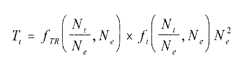
- the impeller torque can be generally described as a function of impeller speed and the speed ratio across the torque converter as follows: where T i is the impeller torque, N e is the engine speed, N t / N e is the speed ratio across the torque converter, with the typical torque converter torque multiplication equation (as a function of speed ratio only) expanded as shown in the equation below, where T t represents torque at the turbine, after the torque converter.
- N ⁇ e is the engine rotational acceleration as a function of time.
- This acceleration torque term I e N ⁇ e ( t ) is accounted for in one embodiment of a system or method according to the present invention by calculating actual engine accelerations that result from the torque output of the engine and adjusting the estimated impeller input torque (T i (t)).
- a natural control law derived from the physical response of the engine and torque converter based on a throttle step command and corresponding engine speed trajectory may be represented by: where the target engine/impeller speed N target / e is a function of turbine speed, desired turbine torque and the torque converter characteristics as represented by: and L represents a time delay in the system, in this example approximately 0.2 seconds.
- N target / e - N e ( t - L ) corresponds to the engine speed error.
- the control law can then be used to produce a control algorithm as described below to determine a desired engine torque from desired turbine torque corresponding to the driver-demanded torque or wheel torque.
- a desired engine speed trajectory or engine acceleration can be determined based on the current engine speed and the target engine speed corresponding to when the torque converter reaches equilibrium. Because the turbine speed and desired turbine torque may be changing on a continuous basis, the present invention was designed to accommodate moving targets.
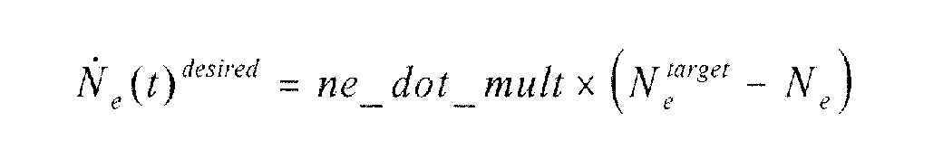
- a desired engine acceleration N ⁇ e ( t ) desired is determined based on the current engine speed error N target / e - N e as represented by: where ne_dot_mult is a calibratable gain factor.
- T desired net ( t ) I e N e ( t ) desired + T i ( t + ⁇ t )
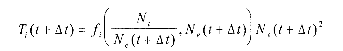
- T i (t + ⁇ t) is the impeller torque at some time in the future due to the desired change in engine speed that results in a change in impeller torque as determined according to the equation below.
- the desired engine acceleration is preferably used in the previous equation rather than the actual engine acceleration because using the actual engine acceleration would produce a positive feedback loop and reduce the proactive nature of this approach.
- the desired engine acceleration can also be used to predict engine speed at some future time. This is advantageous in that waiting for the actual engine acceleration would result in a delay in this component of the torque calculation.
- ⁇ t accounts for the expected delay from desired acceleration to actual acceleration of the engine.
- ⁇ t can be set to one engine revolution. However, the value for ⁇ t may be greater than one engine revolution for many applications.
- the second and third options may be easier to implement between stand-alone engine and transmission controllers because the current engine speed is directly measurable and the target engine speed can be calculated from desired turbine torque and torque converter characteristics.
- the engine controller controls various actuators 64 to produce the desired torque.
- the proportional gain, or trajectory shaping parameter ne_dot_mult was adjusted to achieve a desired response to a throttle step command.
- representative values for the proportional gain ne_dot_mult may be between 3 and 7, for example.
- FIG. 2 a flowchart illustrating operation of one embodiment of a system or method for determining desired engine torque according to the present invention is shown.
- the flowchart illustrated in Figure 2 may represent any of a number of known processing strategies such as event-driven, interrupt-driven, multitasking, multi-threading, and the like. As such, various steps or functions illustrated may be performed in the sequence illustrated, in parallel, or in some cases omitted.
- control logic as represented in Figure 2 is implemented in software which is executed by a microprocessor-based controller.
- control logic may be implemented in software, hardware, or a combination of software and hardware. While not explicitly illustrated, one of ordinary skill in the art will recognize that various steps may be performed iteratively.
- Block 200 of Figure 2 represents determination of a driver-demanded torque.
- driver-demanded torque corresponds to a requested output shaft torque or wheel torque which is determined based on accelerator pedal position, vehicle speed, and barometric pressure.
- the driver-demanded torque may be determined using one or more lookup tables and/or equations stored in a computer readable storage medium in communication with the engine, powertrain, and/or vehicle controller.
- the driver-demanded torque is then used to determine a first engine torque corresponding to a first impeller input torque (T i ) at block 202 based on a steady-state torque converter model (F Ne ) 204 that uses the target engine speed represented by block 206 and described below and various other factors known to those of ordinary skill in the art, which may include currently selected transmission gear ratio, wheel size, and axle ratio, and account for various losses, such as transmission spin losses and torque proportional losses, for example.
- F Ne steady-state torque converter model
- the torque converter model (F Ne ) 204 may be derived from empirical data and is preferably represented by at least two equations corresponding to a two-part curve fit of the empirical data.
- Block 206 determines a target engine speed ( N target / e ) to deliver the desired torque converter turbine torque ( T desired / t ) corresponding to the driver-demanded torque.
- a second engine torque (corresponding to the acceleration torque term I e N ⁇ e ( t ) is determined to increase the engine speed from a current speed to the target engine speed as represented by block 208.
- the second engine torque may be determined to achieve a desired engine acceleration N ⁇ e 210 or an engine speed trajectory 222 based on the current engine speed (Ne resulting in other than desired turbine torque) and the target engine speed N target / e determined in block 206, and is preferably clipped so that it is never less than zero.
- the desired engine acceleration is determined based on a current engine speed error N target / e - N e and a proportional gain factor (ne_dot_mult) as represented by block 214.
- the proportional gain factor is preferably a calibrated value implemented as a function of the measured speed ratio N t / N e as represented by block 218.
- the gain may be calibrated so that at very low speed ratios, the gain is a constant. For all speed ratios where transmission gear shifts are expected to occur, such as speed ratios of about 0.6 and above, the gain may be calibrated to zero, effectively eliminating the second engine torque. For a transition region (of about 0.3 to 0.6, for example), the gain value is preferably linearly interpolated between the low speed ratio value and zero. This limits the inertia compensation to launch of the vehicle.
- the first torque When operating at higher speeds (and corresponding higher speed ratios), the first torque over-estimates the required engine torque.
- driver demand first increases the current value of the torque ratio across the converter (T t /T i ) will be less than or equal to the value after the engine torque (and speed) increases.
- the speed ratio across the converter N t / N e will be lower after the engine speed increases.
- the second engine torque is based on a future torque converter impeller torque (T i (t+ ⁇ t)) calculated using a current turbine speed (N t ) and a future engine speed N e (t+ ⁇ t) corresponding to the future impeller torque as represented by block 224.
- T i (t+ ⁇ t) a future torque converter impeller torque
- the future engine speed may be determined based on the target engine speed ( N target / e ), based on a predicted engine speed for the next engine revolution, or approximated using the current engine speed (N e ) as represented generally by blocks 226, 228, and 230, respectively.
- the second torque may be desirable to modify the second torque to provide a derivative feedback term, which would help prevent overshoots. This provides a similar effect to using predicted values of turbine torque in that both start reducing the magnitude of the second torque before the engine speed reaches the target speed.
- the engine is then controlled to deliver the sum of the first and second engine torques as represented by block 232.
- the present invention provides a controllable and responsive ETC powertrain under wheel torque control by accounting for inertia-based torque loads which occur during transient component rotation speed changes, particularly for vehicle launch and drive away.
- a system and method for controlling a multiple cylinder internal combustion engine including determining a driver-demanded torque, determining a target engine speed to deliver a desired torque converter turbine torque corresponding to the driver-demanded torque based on a torque converter model, determining a first engine torque based on the target engine speed, determining a second engine torque to accelerate the engine speed from a current speed to the target engine speed, and controlling the engine to deliver the sum of the first and second engine torques.
- a system and method for controlling a multiple cylinder internal combustion engine coupled to a transmission via a torque converter having a torque converter impeller selectively fluidly coupled to a torque converter turbine include determining a driver-demanded torque, determining a first engine torque based on the driver-demanded torque and a steady-state model of the torque converter, determining a second engine torque based on a current engine speed and a target engine speed, wherein the second engine torque is based on a speed ratio of turbine speed and impeller speed, and controlling the engine to deliver the sum of the first and second engine torques.
- the present invention provides a number of advantages, for example, the present invention accounts for inertia-based torque loads that occur during transient operation to provide a more responsive control for part-throttle accelerations, particularly for vehicle launch, i.e., when driving away from a complete stop.
- the present invention provides desirable drivability in a full authority electronic throttle control (ETC) system.
- ETC electronic throttle control
- full authority ETC systems may result in reduced losses and increased fuel economy as compared to mechanical throttle and pedal follower systems.
Landscapes
- Engineering & Computer Science (AREA)
- Chemical & Material Sciences (AREA)
- Combustion & Propulsion (AREA)
- Mechanical Engineering (AREA)
- General Engineering & Computer Science (AREA)
- Control Of Transmission Device (AREA)
- Combined Controls Of Internal Combustion Engines (AREA)
- Control Of Vehicle Engines Or Engines For Specific Uses (AREA)
Abstract
Description
- The present invention relates to a system and method for determining desired engine torque for a powertrain having a transmission with a torque converter.
- Internal combustion engines having electronic throttle control (ETC) typically determine a driver-demanded torque based (at least in part) on accelerator pedal position. The driver-demanded torque is typically interpreted as the wheel torque or net torque available to the system to accelerate the vehicle. However, the engine controller can only influence the combustion or indicated torque produced by the engine by controlling the throttle valve position, ignition timing, and fuel injection timing and quantity. To provide the desired output shaft or wheel torque, the indicated or combustion torque produced by the engine must take into account any torque multiplication or reduction provided by the drivetrain, in addition to various losses and engine/vehicle accessory loads. For automatic transmission applications, the torque converter multiplication should be considered. However, the inventors herein have recognized that torque multiplication of the torque converter is dependent upon a variety of operating parameters of the engine and transmission and may be difficult to determine precisely, particularly during transient conditions, using prior art strategies.
- One prior art strategy uses a well-known torque converter relationship between torque ratio and speed ratio to calculate the desired engine combustion torque (or torque converter impeller torque) based on a desired wheel torque and corresponding torque converter turbine torque. This strategy essentially iteratively solves the torque converter equations, which may result in a slow or sluggish response to a driver demand for an increase in output shaft or wheel torque for moderate acceleration, particularly when a vehicle is driving away from a full stop. In addition, this strategy may not adequately account for inertia-based torque loads which occur during transient operation resulting in a sluggish response and poor drivability.
- It is an object of the present invention to provide a system and method for determining a desired engine torque during unlocked torque converter operation from a desired turbine torque to improve the response to an increase in driver-demanded output shaft or wheel torque.
- According to a first aspect of the invention there is provided a method for controlling a multiple cylinder internal combustion engine coupled to a transmission via a torque converter impeller selectively fluidly coupled to a torque converter turbine characterised in that the method comprises determining a driver-demanded torque, determining a target engine speed to deliver a desired torque converter turbine torque corresponding to the driver-demanded torque, determining a first engine torque based on the target engine speed, determining a second engine torque to increase the engine speed from a current speed to the target engine speed and controlling the engine to deliver the sum of the first and second engine torques.
- The step of determining a target engine speed may comprise determining the target engine speed based on a torque converter model.
- Alternatively, the step of determining a target engine speed may comprise determining the target engine speed based on a torque converter model derived from empirical data and represented by at least two equations corresponding to a two-part curve fit of the empirical data.
- The step of determining a first engine torque may comprise determining a steady-state engine brake torque required to maintain the target engine speed.
- The step of determining the second engine torque may comprise determining the second engine torque based on a desired engine acceleration.
- The desired engine acceleration may be determined based on a current engine speed error and a proportional gain factor.
- Alternatively, the step of determining the second engine torque may comprise determining the second engine torque based on a desired engine speed trajectory.
- As yet another alternative, the step of determining the second engine torque comprises determining a future torque converter impeller torque based on a current turbine speed and a future engine speed corresponding to the future impeller torque.
- The future torque converter impeller torque may be determined according to the equations:
- The future engine speed may correspond to the target engine speed, may be a predicted engine speed for the next engine revolution or may be approximated by using the current engine speed.
- According to an alternative embodiment of a method according to the first aspect of the invention there is provided a method for controlling a multiple cylinder internal combustion engine coupled to a transmission via a torque converter having a torque converter impeller selectively fluidly coupled to a torque converter turbine characterised in that the method comprises determining a driver-demanded torque, determining a first engine torque based on the driver-demanded torque and a steady-state model of the torque converter, determining a second engine torque based on a current engine speed and a target engine speed, wherein the second engine torque is based on a speed ratio of turbine speed and impeller speed and controlling the engine to deliver the sum of the first and second engine torques.
- The step of determining a second engine torque may comprise multiplying a difference between the current engine speed and the target engine speed by a gain factor that is a function of the speed ratio.
- The gain factor may be zero, may be a constant or may be limited to values greater than or equal to zero.
- The step of determining a second engine torque may comprise reducing the second engine torque based on a rate of change of the engine speed.
- According to a second aspect of the invention there is provided a system for controlling a multiple cylinder internal combustion engine coupled to a transmission via a torque converter having a torque converter impeller selectively fluidly coupled to a torque converter turbine characterised in that the system comprises an electronic controller having a computer readable medium including stored data representing instructions executable by a computer in communication with at least the internal combustion engine and an accelerator pedal for determining a driver-demanded torque, the electronic controller determining a first engine torque based on the driver-demanded torque and a steady-state model of the torque converter, determining a second engine torque based on a current engine speed, a target engine speed, and a speed ratio of turbine speed and impeller speed, and controlling the engine to deliver the sum of the first and second engine torques.
- The electronic controller may determine a second engine torque by multiplying a difference between the current engine speed and the target engine speed by a gain factor that is a function of the speed ratio.
- The gain factor may be zero, a constant or may be limited to values greater than or equal to zero.
- The electronic controller may determine a final second engine torque by reducing an initial second engine torque based on a rate of change of the engine speed.
- According to a third aspect of the invention there is provided a computer readable medium having stored data representing instructions executable by a computer to control a multiple cylinder internal combustion engine coupled to a transmission via a torque converter having a torque converter impeller selectively fluidly coupled to a torque converter turbine characterised in that the computer readable storage medium comprises instructions for determining a driver-demanded torque, instructions for determining a first engine torque based on the driver-demanded torque and a steady-state model of the torque converter, instructions for determining a second engine torque based on a current engine speed and a target engine speed, wherein the second engine torque is based on a speed ratio of turbine speed and impeller speed and instructions for controlling the engine to deliver the sum of the first and second engine torques.
- The instructions for determining a second engine torque may comprise instructions for multiplying a difference between the current engine speed and the target engine speed by a gain factor that is a function of the speed ratio.
- The gain factor may be zero, a constant or may be limited to values greater than or equal to zero.
- The instructions for determining a second engine torque may comprise instructions for applying a feedback term to reduce overshoot.
- The invention will now be described by way of example with reference to the accompanying drawing of which:-
- Figure 1 is a block diagram illustrating a representative system for determining engine torque according to one embodiment of the present invention; and
- Figure 2 is a flowchart illustrating operation of a system or method for determining engine torque based on a desired turbine torque according to the present invention.
-
- Figure 1 is a block diagram illustrating a system and method for controlling a multiple cylinder internal combustion engine according to one embodiment of the present invention.
System 10 includes avehicular powertrain 12 having aninternal combustion engine 14 coupled to anautomatic transmission 16. Although the present invention is described with reference to a gear change transmission, one of ordinary skill in the art will recognize that the present invention is equally applicable to any transmission having a torque converter, which may include speed change transmissions and continuously variable transmissions (CVT), for example. - Powertrain 12 preferably includes an integrated
powertrain controller 18 in communication withengine 14 andtransmission 16 for providing various information and control functions. Depending upon the particular application, stand-alone engine and transmission controllers may also be used as will be appreciated by those of ordinary skill in the art. - The
engine 14 is connected totransmission 16 viacrankshaft 20 which is connected totransmission pump 22 and/ortorque converter 24. Preferably,torque converter 24 is a hydrodynamic torque converter including a pump orimpeller 26 which is selectively fluidly coupled to aturbine 28.Torque converter 24 may also include a frictional converter clutch orbypass clutch 30 which provides a selective frictional coupling betweenturbine shaft 32 andinput shaft 34. - In one embodiment,
automatic transmission 16 includes a plurality of input-to-output ratios or gear ratios effected by various gears, indicated generally byreference numeral 36, and associated frictional elements such as clutches, bands, and the like, as well known in the art.Gears 36 provide selective reduction or multiplication ratios betweenturbine shaft 32 andoutput shaft 38. - The
automatic transmission 16 is preferably electronically controlled via one or more shift solenoids, indicated generally byreference numeral 40, and a converter clutch control (CC) 41 to select an appropriate gear ratio based on current operating conditions.Transmission 16 also preferably includes an actuator for controlling pump pressure (PP) 42 (or line pressure), in addition to a shift lever position sensor (PRN) 44 to provide an indication of the operator's selected gear or driving mode, such as drive, reverse, park, etc. A line pressure sensor (LP) 46 can be provided to facilitate closed loop feedback control of the hydraulic line pressure during shifting or ratio changing. - Depending upon the particular application,
output shaft 38 may be coupled to one ormore axles 48 via a final drive reduction ordifferential 50 which may include one or more gears, as indicated generally byreference numeral 52. Eachaxle 48 may include two ormore wheels 54 having correspondingwheel speed sensors 56. - In addition to the sensors described above,
powertrain 12 preferably includes a plurality of sensors, indicated generally byreference numeral 60, in communication withcorresponding input ports 62 ofcontroller 18 to sense or monitor the current operating and ambient conditions ofpowertrain 12. A plurality of actuators, indicated generally byreference numeral 64, communicates withcontroller 18 viaoutput ports 66 to effect control ofpowertrain 12 in response to commands generated bycontroller 18. - The sensors preferably include a throttle valve position sensor (TPS) 68 which monitors the position of
throttle valve 70 which is disposed withinintake 72. A mass airflow sensor (MAF) 74 provides an indication of the air mass flowing throughintake 72. A temperature sensor (TMP) 76 provides an indication of the engine temperature which may include engine coolant temperature or engine oil temperature, for example. - An engine speed sensor (RPM) 80 monitors the rotational speed of
crankshaft 20 and similarly, aturbine speed sensor 82 monitors the rotational speed of theturbine 28 oftorque converter 24. Another rotational speed sensor, output shaft speed sensor (OSS) 84, provides an indication of the speed ofoutput shaft 38 which may be used to determine the vehicle speed based on the ratio ofdifferential 50 and the size ofwheels 54. Of course, wheel speed sensors (WS1 and WS2) 56 may be used to provide an indication of the vehicle speed as well. - Depending upon the particular application requirements, various sensors may be omitted or alternative sensors provided which generate signals indicative of related sensed parameters. Values corresponding to ambient or operating conditions may be inferred or calculated using one or more of the sensed parameters without departing from the spirit or scope of the present invention.
- An
accelerator pedal 58 is manipulated by the driver to request a driver-demanded output shaft torque or wheel torque that is used to control the output ofpowertrain 12. - A
pedal position sensor 59 provides an indication of the position ofaccelerator pedal 58, preferably in the form of counts. In one embodiment, an increasing number of counts indicates a request for increased power output. Preferably, redundant position sensors are used with at least one position sensor having a negative slope such that a decreasing number of counts corresponds to a request for increased power output. A manifold absolute pressure (MAP) sensor, or equivalent, may be used to provide an indication of the current barometric pressure. -
Actuators 64 are used to provide control signals or to effect movement of various devices inpowertrain 12. - The
actuators 64 may include actuators for timing and metering fuel (FUEL) 90, controlling ignition angle or timing (SPK) 92, controlling intake/exhaust valve actuators 93 (VCT) to implement variable cam timing, setting the amount of exhaust gas recirculation (EGR) 94, and adjusting the intake air usingthrottle valve 70 with an appropriate servomotor or actuator (TVA) 96. As described above,automatic transmission 16 may be selectively controlled by controlling transmission pump or line pressure using an appropriate actuator (PP) 42 in combination with shift solenoids (SS1 and SS2) 40 which are used to select an appropriate gear ratio, and a converter clutch actuator or solenoid (CC) 41 used to lock, unlock or control slip of thetorque converter clutch 30. Also preferably, a temperature sensor 106 is provided to determine the transmission oil temperature (TOT). - The
controller 18 is preferably a microprocessor-based controller which provides integrated control ofengine 14 andtransmission 16 ofpowertrain 12. Of course, the present invention may be implemented using separate engine and transmission controllers depending upon the particular application as described above. -
Controller 18 includes amicroprocessor 110 in communication withinput ports 62,output ports 66, and computerreadable media 112 via a data/control bus 114. Computerreadable media 112 may include various types of volatile and nonvolatile memory such as random access memory (RAM) 116, read-only memory (ROM) 118, and keep-alive memory (KAM) 119. These "functional" descriptions of the various types of volatile and nonvolatile storage may be implemented by any of a number of known physical devices including but not limited to EPROMs, EEPROMs, PROMS, flash memory, and the like. Computerreadable media 112 include stored data representing instructions executable bymicroprocessor 110 to implement the method for controlling engine torque according to the present invention. - In operation, torque is applied through
engine 14 throughcrankshaft 20 toimpeller 26 oftorque converter 24. Torque is transferred through the transmission fluid toturbine 28 which in turn causesdriveshaft 38 to rotate based on the selected gear ratio ofgearbox 36. Unlike the prior art approach which uses steady-state derived equations to model the static and dynamic torque converter characteristics, the present invention provides transient equations which take into account accelerated inertia-based torque loads which occur during rotational speed changes of engine and transmission components. - Beginning with a known steady-state modeling approach for the torque converter:
- N ˙e represents engine acceleration, Tnet(t) is the net engine output torque (indicated torque less friction, pumping, accessories and transmission pump losses), and Ti(t) is the reaction torque from the torque converter impeller. As also known, the impeller torque can be generally described as a function of impeller speed and the speed ratio across the torque converter as follows:where Ti is the impeller torque, Ne is the engine speed, Nt / Ne is the speed ratio across the torque converter, with the typical torque converter torque multiplication equation (as a function of speed ratio only) expanded as shown in the equation below, where Tt represents torque at the turbine, after the torque converter.


- Combining the above equations provides:
- From the previous equation, it is clear that to achieve a certain turbine torque at a given turbine speed, there is a required engine/impeller speed. The first equation shows that any additional torque from the engine in excess of the impeller torque will result in engine and impeller acceleration, not additional turbine torque. The time period between an increase in requested wheel torque (translated to turbine torque) and the realization of that torque increase will be a function of the engine speed trajectory. The first equation can be rearranged to determine impeller input torque, showing that the acceleration of the engine and impeller uses torque that otherwise would be transferred to the wheels, as follows:
- N ˙e is the engine rotational acceleration as a function of time.
- This acceleration torque term IeN ˙e (t) is accounted for in one embodiment of a system or method according to the present invention by calculating actual engine accelerations that result from the torque output of the engine and adjusting the estimated impeller input torque (Ti(t)).
- A natural control law derived from the physical response of the engine and torque converter based on a throttle step command and corresponding engine speed trajectory may be represented by:where the target engine/impeller speed N target / e is a function of turbine speed, desired turbine torque and the torque converter characteristics as represented by:
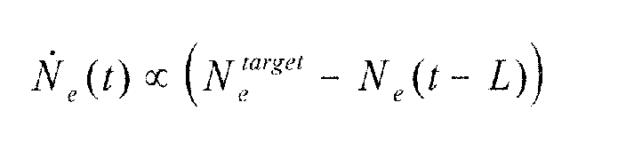 and L represents a time delay in the system, in this example approximately 0.2 seconds.
- The term N target / e - Ne (t - L) corresponds to the engine speed error. The control law can then be used to produce a control algorithm as described below to determine a desired engine torque from desired turbine torque corresponding to the driver-demanded torque or wheel torque.
- According to the present invention, a desired engine speed trajectory or engine acceleration can be determined based on the current engine speed and the target engine speed corresponding to when the torque converter reaches equilibrium. Because the turbine speed and desired turbine torque may be changing on a continuous basis, the present invention was designed to accommodate moving targets. Starting from a torque converter mapping of engine/impeller speed to produce a desired turbine torque as represented by the function FNe in the equation above, a desired engine acceleration N ˙e (t) desired is determined based on the current engine speed error N target / e - Ne as represented by:where ne_dot_mult is a calibratable gain factor. The goal of this embodiment of the control algorithm is to determine a desired Tnet, which can be expressed by:
- The impeller torque at some future time may be represented by:

- The term Δt accounts for the expected delay from desired acceleration to actual acceleration of the engine.
- If the only cause of this delay is the delay from charge induction to cylinder power events, Δt can be set to one engine revolution. However, the value for Δt may be greater than one engine revolution for many applications.
- The future engine speed used for the impeller load torque calculations (represented by Ne(t + Δt)), may be calculated in various ways depending upon the particular application. This future engine speed may be calculated by predicting engine speed one revolution into the future, as shown in the previous equation, may be set to the target engine speed as calculated as indicated above, or may be determined using the current engine speed, which is equivalent to setting Δt = 0.
- The second and third options may be easier to implement between stand-alone engine and transmission controllers because the current engine speed is directly measurable and the target engine speed can be calculated from desired turbine torque and torque converter characteristics.
- Once the desired engine indicated or combustion torque represented by T desired / t has been determined from the above equations, the engine controller controls
various actuators 64 to produce the desired torque. - The representative control algorithm according to the present invention as described above was implemented in C-code and tested using a vehicle powertrain simulator. The torque converter characteristics used in the equations were simplified by assuming brake torque (Nt = 0) conditions only (both Tt and Ti reduce to linear functions of N2 e).
- Using a two degree accelerator pedal step input, the proportional gain, or trajectory shaping parameter ne_dot_mult was adjusted to achieve a desired response to a throttle step command. Depending upon the particular application, representative values for the proportional gain ne_dot_mult may be between 3 and 7, for example. To evaluate the performance of a representative embodiment of the present invention under normal launch and drive-away conditions, simulation data was used to develop a set of equations that approximate the relationships for turbine torque and impeller torque used in the equations. This simulation demonstrated improved performance of the present invention under different tip-in conditions.
- Referring now to Figure 2, a flowchart illustrating operation of one embodiment of a system or method for determining desired engine torque according to the present invention is shown. As will be appreciated by one of ordinary skill in the art, the flowchart illustrated in Figure 2 may represent any of a number of known processing strategies such as event-driven, interrupt-driven, multitasking, multi-threading, and the like. As such, various steps or functions illustrated may be performed in the sequence illustrated, in parallel, or in some cases omitted.
- Likewise, the order of processing as represented by the figures and in the claims is not necessarily required to achieve the objects, features, and advantages of the invention, but is provided for ease of illustration and description. Preferably, control logic as represented in Figure 2 is implemented in software which is executed by a microprocessor-based controller. Of course, the control logic may be implemented in software, hardware, or a combination of software and hardware. While not explicitly illustrated, one of ordinary skill in the art will recognize that various steps may be performed iteratively.
-
Block 200 of Figure 2 represents determination of a driver-demanded torque. In one embodiment, driver-demanded torque corresponds to a requested output shaft torque or wheel torque which is determined based on accelerator pedal position, vehicle speed, and barometric pressure. The driver-demanded torque may be determined using one or more lookup tables and/or equations stored in a computer readable storage medium in communication with the engine, powertrain, and/or vehicle controller. - The driver-demanded torque is then used to determine a first engine torque corresponding to a first impeller input torque (Ti) at
block 202 based on a steady-state torque converter model (FNe) 204 that uses the target engine speed represented byblock 206 and described below and various other factors known to those of ordinary skill in the art, which may include currently selected transmission gear ratio, wheel size, and axle ratio, and account for various losses, such as transmission spin losses and torque proportional losses, for example. - The torque converter model (FNe) 204 may be derived from empirical data and is preferably represented by at least two equations corresponding to a two-part curve fit of the empirical data.
-
Block 206 determines a target engine speed (N target / e) to deliver the desired torque converter turbine torque (T desired / t) corresponding to the driver-demanded torque. - A second engine torque (corresponding to the acceleration torque term IeN ˙e (t) is determined to increase the engine speed from a current speed to the target engine speed as represented by
block 208. - The second engine torque may be determined to achieve a desired engine acceleration N ˙e 210 or an engine speed trajectory 222 based on the current engine speed (Ne resulting in other than desired turbine torque) and the target engine speed N target / e determined in
block 206, and is preferably clipped so that it is never less than zero. - In one embodiment, the desired engine acceleration is determined based on a current engine speed error N target / e - Ne and a proportional gain factor (ne_dot_mult) as represented by
block 214. - The proportional gain factor is preferably a calibrated value implemented as a function of the measured speed ratio Nt / Ne as represented by
block 218. - The gain may be calibrated so that at very low speed ratios, the gain is a constant. For all speed ratios where transmission gear shifts are expected to occur, such as speed ratios of about 0.6 and above, the gain may be calibrated to zero, effectively eliminating the second engine torque. For a transition region (of about 0.3 to 0.6, for example), the gain value is preferably linearly interpolated between the low speed ratio value and zero. This limits the inertia compensation to launch of the vehicle.
- When operating at higher speeds (and corresponding higher speed ratios), the first torque over-estimates the required engine torque. When driver demand first increases, the current value of the torque ratio across the converter (Tt/Ti) will be less than or equal to the value after the engine torque (and speed) increases.
- The speed ratio across the converter Nt / Ne will be lower after the engine speed increases.
- As such, at the higher speed ratios, a desirable quick response is provided without requiring the second torque and the gain is set to zero for these speed ratios. This approach is also less dependent on an exact torque converter model.
- In one embodiment, the second engine torque is based on a future torque converter impeller torque (Ti(t+Δt)) calculated using a current turbine speed (Nt) and a future engine speed Ne(t+Δt) corresponding to the future impeller torque as represented by
block 224. - The future engine speed may be determined based on the target engine speed (N target / e), based on a predicted engine speed for the next engine revolution, or approximated using the current engine speed (Ne) as represented generally by
blocks - Depending on the particular application, it may be desirable to modify the second torque to provide a derivative feedback term, which would help prevent overshoots. This provides a similar effect to using predicted values of turbine torque in that both start reducing the magnitude of the second torque before the engine speed reaches the target speed.
- The engine is then controlled to deliver the sum of the first and second engine torques as represented by
block 232. - As illustrated by the representative embodiment described in detail above, the present invention provides a controllable and responsive ETC powertrain under wheel torque control by accounting for inertia-based torque loads which occur during transient component rotation speed changes, particularly for vehicle launch and drive away.
- Therefore in summary a system and method for controlling a multiple cylinder internal combustion engine are provided including determining a driver-demanded torque, determining a target engine speed to deliver a desired torque converter turbine torque corresponding to the driver-demanded torque based on a torque converter model, determining a first engine torque based on the target engine speed, determining a second engine torque to accelerate the engine speed from a current speed to the target engine speed, and controlling the engine to deliver the sum of the first and second engine torques.
- In another embodiment of the invention, a system and method for controlling a multiple cylinder internal combustion engine coupled to a transmission via a torque converter having a torque converter impeller selectively fluidly coupled to a torque converter turbine include determining a driver-demanded torque, determining a first engine torque based on the driver-demanded torque and a steady-state model of the torque converter, determining a second engine torque based on a current engine speed and a target engine speed, wherein the second engine torque is based on a speed ratio of turbine speed and impeller speed, and controlling the engine to deliver the sum of the first and second engine torques.
- The present invention provides a number of advantages, for example, the present invention accounts for inertia-based torque loads that occur during transient operation to provide a more responsive control for part-throttle accelerations, particularly for vehicle launch, i.e., when driving away from a complete stop. In addition, the present invention provides desirable drivability in a full authority electronic throttle control (ETC) system. As known, full authority ETC systems may result in reduced losses and increased fuel economy as compared to mechanical throttle and pedal follower systems.
- While the best modes for carrying out the invention have been described in detail, those familiar with the art to which this invention relates will recognize various alternative designs and embodiments for practicing the invention could be constructed without departing from the scope of the invention.
Claims (10)
- A method for controlling a multiple cylinder internal combustion engine (14) coupled to a transmission (16) via a torque converter impeller (26) selectively fluidly coupled to a torque converter turbine (28) characterised in that the method comprises determining a driver-demanded torque, determining a target engine speed to deliver a desired torque converter turbine torque corresponding to the driver-demanded torque, determining a first engine torque based on the target engine speed, determining a second engine torque to increase the engine speed from a current speed to the target engine speed and controlling the engine to deliver the sum of the first and second engine torques.
- A method as claimed in claim 1 wherein the step of determining a target engine speed comprises determining the target engine speed based on a torque converter model.
- A method as claimed in claim 1 wherein the step of determining a target engine speed comprises determining the target engine speed based on a torque converter model derived from empirical data and represented by at least two equations corresponding to a two-part curve fit of the empirical data.
- A method as claimed in any of claims 1 to 3 wherein the step of determining a first engine torque comprises determining a steady-state engine brake torque required to maintain the target engine speed.
- A method as claimed in any of claims 1 to 4 wherein the step of determining the second engine torque comprises determining the second engine torque based on a desired engine acceleration.
- A method as claimed in claim 5 wherein the desired engine acceleration is determined based on a current engine speed error and a proportional gain factor.
- A method as claimed in any of claims 1 to 4 wherein the step of determining the second engine torque comprises determining the second engine torque based on a desired engine speed trajectory.
- A method as claimed in any of claims 1 to 4 wherein the step of determining the second engine torque comprises determining a future torque converter impeller torque based on a current turbine speed and a future engine speed corresponding to the future impeller torque.
- A system for controlling a multiple cylinder internal combustion engine (14) coupled to a transmission (16) via a torque converter (24) having a torque converter impeller (26) selectively fluidly coupled to a torque converter turbine (28) characterised in that the system comprises an electronic controller (18) having a computer readable medium (112) including stored data representing instructions executable by a computer (110) in communication with at least the internal combustion engine (14) and an accelerator pedal (58) for determining a driver-demanded torque, the electronic controller (18) determining a first engine torque based on the driver-demanded torque and a steady-state model of the torque converter (24), determining a second engine torque based on a current engine speed, a target engine speed, and a speed ratio of turbine speed and impeller speed, and controlling the engine (14) to deliver the sum of the first and second engine torques.
- A computer readable medium (112) having stored data representing instructions executable by a computer (110) to control a multiple cylinder internal combustion engine (14) coupled to a transmission (16) via a torque converter (24) having a torque converter impeller (26) selectively fluidly coupled to a torque converter turbine (28) characterised in that the computer readable storage medium (112) comprises instructions for determining a driver-demanded torque, instructions for determining a first engine torque based on the driver-demanded torque and a steady-state model of the torque converter, instructions for determining a second engine torque based on a current engine speed and a target engine speed, wherein the second engine torque is based on a speed ratio of turbine speed and impeller speed and instructions for controlling the engine (14) to deliver the sum of the first and second engine torques.
Applications Claiming Priority (2)
| Application Number | Priority Date | Filing Date | Title |
|---|---|---|---|
| US682948 | 1984-12-18 | ||
| US09/682,948 US6701246B2 (en) | 2001-11-02 | 2001-11-02 | Engine torque determination for powertrain with torque converter |
Publications (2)
| Publication Number | Publication Date |
|---|---|
| EP1308342A2 true EP1308342A2 (en) | 2003-05-07 |
| EP1308342A3 EP1308342A3 (en) | 2006-05-10 |
Family
ID=24741908
Family Applications (1)
| Application Number | Title | Priority Date | Filing Date |
|---|---|---|---|
| EP02102497A Withdrawn EP1308342A3 (en) | 2001-11-02 | 2002-10-27 | An engine torque determination for a powertrain with torque converter |
Country Status (2)
| Country | Link |
|---|---|
| US (1) | US6701246B2 (en) |
| EP (1) | EP1308342A3 (en) |
Cited By (4)
| Publication number | Priority date | Publication date | Assignee | Title |
|---|---|---|---|---|
| WO2005056996A1 (en) * | 2003-12-11 | 2005-06-23 | Robert Bosch Gmbh | Method and device for operating a drive unit |
| WO2005098223A1 (en) * | 2004-04-06 | 2005-10-20 | Robert Bosch Gmbh | Method for the operation of a drive train of a motor vehicle, and arrangement for the operation of a drive train |
| DE102007002746B4 (en) * | 2006-01-18 | 2010-04-01 | Toyota Jidosha Kabushiki Kaisha, Toyota-shi | Estimated torque calculating device for an internal combustion engine and related method |
| BE1022961B1 (en) * | 2015-07-16 | 2016-10-24 | Cnh Industrial Belgium Nv | Method and device for controlling the motor speed of a work machine |
Families Citing this family (26)
| Publication number | Priority date | Publication date | Assignee | Title |
|---|---|---|---|---|
| US6909958B2 (en) * | 2003-05-12 | 2005-06-21 | Honda Giken Kogyo Kabushiki Kaisha | System and method for inhibiting torque steer |
| JP2005090353A (en) * | 2003-09-17 | 2005-04-07 | Hino Motors Ltd | Transient engine performance adaptation method and system |
| US6840215B1 (en) * | 2003-09-17 | 2005-01-11 | General Motors Corporation | Engine torque control with desired state estimation |
| US6847879B1 (en) * | 2004-01-30 | 2005-01-25 | Daimlerchrysler Corporation | Method of controlling torque converter clutch slip |
| US7021282B1 (en) * | 2004-12-01 | 2006-04-04 | General Motors Corporation | Coordinated engine torque control |
| US7425187B2 (en) * | 2005-07-27 | 2008-09-16 | Ford Global Technologies, Llc | System and method for improved fuel economy during vehicle deceleration conditions |
| DE102006061438A1 (en) * | 2006-12-23 | 2008-06-26 | Dr.Ing.H.C. F. Porsche Ag | Method and control unit for checking a Saugrohrlängenverstellung in an internal combustion engine |
| JP4840135B2 (en) * | 2006-12-30 | 2011-12-21 | トヨタ自動車株式会社 | Control device for vehicle drive device |
| US8195370B2 (en) * | 2007-07-16 | 2012-06-05 | GM Global Technology Operations LLC | Association of torque requesting modules in a coordinated torque architecture |
| US8437938B2 (en) * | 2008-01-15 | 2013-05-07 | GM Global Technology Operations LLC | Axle torque based cruise control |
| DE602008001371D1 (en) * | 2008-04-10 | 2010-07-08 | Fiat Ricerche | Turbofuel engine with variable control of intake valves |
| US7844404B2 (en) * | 2008-12-17 | 2010-11-30 | Honeywell International Inc. | Systems and methods for determining engine torque values |
| US8290689B2 (en) * | 2009-04-14 | 2012-10-16 | GM Global Technology Operations LLC | Variable exhaust brake control via turbine vane positioning |
| US8027780B2 (en) * | 2009-05-01 | 2011-09-27 | GM Global Technology Operations LLC | Method and system for controlling torque during a vehicle launch condition |
| US8079335B2 (en) * | 2009-09-17 | 2011-12-20 | Ford Global Technologies, Llc | Inferred oil responsiveness using pressure sensor pulses |
| US8594904B2 (en) * | 2011-09-23 | 2013-11-26 | GM Global Technology Operations LLC | System and method for securing engine torque requests |
| US8919323B2 (en) * | 2012-03-27 | 2014-12-30 | GM Global Technology Operations LLC | System and method for controlling engine speed |
| US9731725B2 (en) | 2012-09-05 | 2017-08-15 | Ford Global Technologies, Llc | Control of vehicle driveline torque |
| US9031722B2 (en) | 2012-12-10 | 2015-05-12 | Ford Global Technologies, Llc | Method and system for improving hybrid vehicle shifting |
| US9057333B2 (en) | 2013-07-31 | 2015-06-16 | GM Global Technology Operations LLC | System and method for controlling the amount of torque provided to wheels of a vehicle to improve drivability |
| US9090245B2 (en) | 2013-07-31 | 2015-07-28 | GM Global Technology Operations LLC | System and method for controlling the amount of torque provided to wheels of a vehicle to prevent unintended acceleration |
| US9701299B2 (en) * | 2014-02-27 | 2017-07-11 | GM Global Technology Operations LLC | System and method for controlling an engine based on a desired turbine power to account for losses in a torque converter |
| DE102016204356B4 (en) * | 2016-03-16 | 2022-02-10 | Ford Global Technologies, Llc | Method and device for longitudinal control of a motor vehicle |
| US9914448B2 (en) * | 2016-06-20 | 2018-03-13 | GM Global Technology Operations LLC | Control of multiple torque actuators across at least two controllers in a powertrain assembly |
| US10458351B2 (en) | 2017-12-01 | 2019-10-29 | Fca Us Llc | Engine torque reserve techniques for optimizing drag racing transient response |
| US10746291B2 (en) | 2019-01-17 | 2020-08-18 | Ford Global Technologies, Llc | Engine torque and torque converter bypass clutch slip control during vehicle launch |
Family Cites Families (9)
| Publication number | Priority date | Publication date | Assignee | Title |
|---|---|---|---|---|
| JPH0441940A (en) * | 1990-06-06 | 1992-02-12 | Nissan Motor Co Ltd | Control device of engine for vehicle |
| JP3318945B2 (en) | 1992-03-02 | 2002-08-26 | 株式会社日立製作所 | Vehicle control device, vehicle control system and vehicle control method |
| EP0687809B1 (en) | 1994-06-17 | 2001-08-29 | Hitachi, Ltd. | An output torque control apparatus and method for an internal combustion engine |
| DE19632337C2 (en) * | 1996-08-10 | 2000-12-14 | Daimler Chrysler Ag | Method and device for regulating the longitudinal dynamics of a motor vehicle |
| DE69839616D1 (en) * | 1997-04-25 | 2008-07-24 | Hitachi Ltd | Method for setting a target drive torque and corresponding vehicle control |
| DE19802217A1 (en) * | 1997-10-17 | 1999-04-22 | Itt Mfg Enterprises Inc | Method of determining motor vehicle drive torque when starting, determining an externally generated driving or braking parameter and aiding starting on hills |
| US6199004B1 (en) * | 1999-05-17 | 2001-03-06 | Ford Global Technologies, Inc. | Vehicle and engine control system |
| US6279531B1 (en) * | 1999-08-09 | 2001-08-28 | Ford Global Technologies, Inc. | System and method for controlling engine torque |
| US6165102A (en) * | 1999-11-22 | 2000-12-26 | Cummins Engine Company, Inc. | System for controlling output torque characteristics of an internal combustion engine |
-
2001
- 2001-11-02 US US09/682,948 patent/US6701246B2/en not_active Expired - Lifetime
-
2002
- 2002-10-27 EP EP02102497A patent/EP1308342A3/en not_active Withdrawn
Non-Patent Citations (1)
| Title |
|---|
| None |
Cited By (8)
| Publication number | Priority date | Publication date | Assignee | Title |
|---|---|---|---|---|
| WO2005056996A1 (en) * | 2003-12-11 | 2005-06-23 | Robert Bosch Gmbh | Method and device for operating a drive unit |
| CN100465421C (en) * | 2003-12-11 | 2009-03-04 | 罗伯特·博世有限公司 | Method and device for operating a drive unit |
| WO2005098223A1 (en) * | 2004-04-06 | 2005-10-20 | Robert Bosch Gmbh | Method for the operation of a drive train of a motor vehicle, and arrangement for the operation of a drive train |
| DE102007002746B4 (en) * | 2006-01-18 | 2010-04-01 | Toyota Jidosha Kabushiki Kaisha, Toyota-shi | Estimated torque calculating device for an internal combustion engine and related method |
| BE1022961B1 (en) * | 2015-07-16 | 2016-10-24 | Cnh Industrial Belgium Nv | Method and device for controlling the motor speed of a work machine |
| WO2017009470A1 (en) * | 2015-07-16 | 2017-01-19 | Cnh Industrial Belgium Nv | Method and apparatus for controlling engine speed of a work machine |
| US10253703B2 (en) | 2015-07-16 | 2019-04-09 | Cnh Industrial America Llc | Method and apparatus for controlling engine speed of a work machine |
| RU2716734C2 (en) * | 2015-07-16 | 2020-03-16 | СиЭнЭйч ИНДАСТРИАЛ БЕЛДЖИУМ НВ | Method and device for controlling working machine engine rpm |
Also Published As
| Publication number | Publication date |
|---|---|
| US20030097215A1 (en) | 2003-05-22 |
| US6701246B2 (en) | 2004-03-02 |
| EP1308342A3 (en) | 2006-05-10 |
Similar Documents
| Publication | Publication Date | Title |
|---|---|---|
| US6701246B2 (en) | Engine torque determination for powertrain with torque converter | |
| US6220987B1 (en) | Automatic transmission ratio change schedules based on desired powertrain output | |
| US6434466B1 (en) | System and method for determining engine torque for controlling a powertrain | |
| US6279531B1 (en) | System and method for controlling engine torque | |
| US6991584B2 (en) | Control of powertrain smoothness using output torque sensing and input torque control | |
| US7393305B2 (en) | Controller for automatic transmission | |
| US6920865B2 (en) | Mechatronic vehicle powertrain control system | |
| CA1217835A (en) | Electronic control method for vehicles | |
| EP1074717B1 (en) | System and method for determining engine control parameters based on engine torque | |
| US8498789B2 (en) | Control apparatus and control method for drive source | |
| US8935063B2 (en) | Control apparatus and control method for vehicle | |
| CN105936280A (en) | Methods and system for providing vehicle performance feedback | |
| CN101886698B (en) | Torque converter clutch control | |
| US20100274460A1 (en) | Control apparatus and control method for power source | |
| US6364812B1 (en) | Automatic transmission dynamic electronic pressure control based on desired powertrain output | |
| US9523428B2 (en) | System and method for shift restraint control | |
| US7983826B2 (en) | Control apparatus and control method for drive source | |
| US8019524B2 (en) | Control apparatus for driving source | |
| GB2380776A (en) | Method of determining engine torque which is used to control a powertrain | |
| JP4872985B2 (en) | Drive source control device | |
| JP2020002896A (en) | Internal combustion engine control device | |
| US20180023698A1 (en) | Control device for vehicle and control method for vehicle | |
| JPS6397834A (en) | Automatic transmission control device for gas turbine car | |
| CN110630389A (en) | Method for determining engine control parameters based on requested engine braking torque |
Legal Events
| Date | Code | Title | Description |
|---|---|---|---|
| PUAI | Public reference made under article 153(3) epc to a published international application that has entered the european phase |
Free format text: ORIGINAL CODE: 0009012 |
|
| AK | Designated contracting states |
Designated state(s): AT BE BG CH CY CZ DE DK EE ES FI FR GB GR IE IT LI LU MC NL PT SE SK TR |
|
| AX | Request for extension of the european patent |
Extension state: AL LT LV MK RO SI |
|
| PUAL | Search report despatched |
Free format text: ORIGINAL CODE: 0009013 |
|
| AK | Designated contracting states |
Kind code of ref document: A3 Designated state(s): AT BE BG CH CY CZ DE DK EE ES FI FR GB GR IE IT LI LU MC NL PT SE SK TR |
|
| AX | Request for extension of the european patent |
Extension state: AL LT LV MK RO SI |
|
| RIC1 | Information provided on ipc code assigned before grant |
Ipc: F02D 41/14 20060101ALI20060320BHEP Ipc: B60K 41/16 00000000AFI20030226BHEP |
|
| 17P | Request for examination filed |
Effective date: 20061023 |
|
| AKX | Designation fees paid |
Designated state(s): DE GB |
|
| 17Q | First examination report despatched |
Effective date: 20070829 |
|
| STAA | Information on the status of an ep patent application or granted ep patent |
Free format text: STATUS: THE APPLICATION IS DEEMED TO BE WITHDRAWN |
|
| 18D | Application deemed to be withdrawn |
Effective date: 20091208 |