EP1308338A2 - Power distribution method and power distribution control apparatus for vehicle - Google Patents
Power distribution method and power distribution control apparatus for vehicle Download PDFInfo
- Publication number
- EP1308338A2 EP1308338A2 EP02024195A EP02024195A EP1308338A2 EP 1308338 A2 EP1308338 A2 EP 1308338A2 EP 02024195 A EP02024195 A EP 02024195A EP 02024195 A EP02024195 A EP 02024195A EP 1308338 A2 EP1308338 A2 EP 1308338A2
- Authority
- EP
- European Patent Office
- Prior art keywords
- temperature
- power distribution
- distribution ratio
- power
- transmission apparatus
- Prior art date
- Legal status (The legal status is an assumption and is not a legal conclusion. Google has not performed a legal analysis and makes no representation as to the accuracy of the status listed.)
- Granted
Links
- 238000000034 method Methods 0.000 title claims abstract description 16
- 230000005540 biological transmission Effects 0.000 claims abstract description 63
- 230000003247 decreasing effect Effects 0.000 claims description 12
- 230000007423 decrease Effects 0.000 claims description 7
- 239000010687 lubricating oil Substances 0.000 description 27
- 239000003921 oil Substances 0.000 description 15
- 230000001050 lubricating effect Effects 0.000 description 14
- 238000005461 lubrication Methods 0.000 description 2
- 238000002485 combustion reaction Methods 0.000 description 1
- 238000010586 diagram Methods 0.000 description 1
Images


Classifications
-
- B—PERFORMING OPERATIONS; TRANSPORTING
- B60—VEHICLES IN GENERAL
- B60K—ARRANGEMENT OR MOUNTING OF PROPULSION UNITS OR OF TRANSMISSIONS IN VEHICLES; ARRANGEMENT OR MOUNTING OF PLURAL DIVERSE PRIME-MOVERS IN VEHICLES; AUXILIARY DRIVES FOR VEHICLES; INSTRUMENTATION OR DASHBOARDS FOR VEHICLES; ARRANGEMENTS IN CONNECTION WITH COOLING, AIR INTAKE, GAS EXHAUST OR FUEL SUPPLY OF PROPULSION UNITS IN VEHICLES
- B60K23/00—Arrangement or mounting of control devices for vehicle transmissions, or parts thereof, not otherwise provided for
- B60K23/08—Arrangement or mounting of control devices for vehicle transmissions, or parts thereof, not otherwise provided for for changing number of driven wheels, for switching from driving one axle to driving two or more axles
- B60K23/0808—Arrangement or mounting of control devices for vehicle transmissions, or parts thereof, not otherwise provided for for changing number of driven wheels, for switching from driving one axle to driving two or more axles for varying torque distribution between driven axles, e.g. by transfer clutch
-
- B—PERFORMING OPERATIONS; TRANSPORTING
- B60—VEHICLES IN GENERAL
- B60K—ARRANGEMENT OR MOUNTING OF PROPULSION UNITS OR OF TRANSMISSIONS IN VEHICLES; ARRANGEMENT OR MOUNTING OF PLURAL DIVERSE PRIME-MOVERS IN VEHICLES; AUXILIARY DRIVES FOR VEHICLES; INSTRUMENTATION OR DASHBOARDS FOR VEHICLES; ARRANGEMENTS IN CONNECTION WITH COOLING, AIR INTAKE, GAS EXHAUST OR FUEL SUPPLY OF PROPULSION UNITS IN VEHICLES
- B60K17/00—Arrangement or mounting of transmissions in vehicles
- B60K17/34—Arrangement or mounting of transmissions in vehicles for driving both front and rear wheels, e.g. four wheel drive vehicles
- B60K17/348—Arrangement or mounting of transmissions in vehicles for driving both front and rear wheels, e.g. four wheel drive vehicles having differential means for driving one set of wheels, e.g. the front, at one speed and the other set, e.g. the rear, at a different speed
- B60K17/35—Arrangement or mounting of transmissions in vehicles for driving both front and rear wheels, e.g. four wheel drive vehicles having differential means for driving one set of wheels, e.g. the front, at one speed and the other set, e.g. the rear, at a different speed including arrangements for suppressing or influencing the power transfer, e.g. viscous clutches
Definitions
- the present invention relates to a power distribution method and a power distribution control apparatus for vehicles.
- a standby four-wheel drive system is known in the art.
- the standby four-wheel drive system controls distribution of power to the front wheels and the rear wheels according to the driving state of a vehicle.
- a transmission apparatus which is capable of changing the power distribution ratio to the front wheels and the rear wheels.
- a typical transmission apparatus includes an electromagnetic clutch mechanism of a multi-plate wet type.
- the frictional force among the clutch disks of the electromagnetic clutch mechanism is varied in accordance with the amount of the current supplied to a magnet coil. As the frictional force is increased, the ratio of the power distribution to the rear wheels is increased.
- one aspect of the present invention provides a method for distributing power of a vehicle.
- the vehicle has a transmission apparatus that changes the distribution ratio of power transmitted from a power source to a plurality of wheels.
- the method includes detecting the temperature of a part located on a power transmission path between the power source and a wheel to which power is transmitted from the power source through the transmission apparatus, the heat of the part being increased as the power distribution ratio is increased; determining that the current state is a specitic state in which the detected temperature reaches a previously set first reference temperature; and controlling the transmission apparatus to lower the power distribution ratio to the wheel from the transmission apparatus when the current state is determined to the specified state.
- the control apparatus includes a transmission apparatus that changes the distribution ratio of power transmitted from a power source to a plurality of wheels.
- the control apparatus has a detector and an electronic control unit.
- the detector detects the temperature of a part located on a power transmission path between the power source and a wheel to which power is transmitted from the power source through the transmission apparatus, the heat of the part being increased as the power distribution ratio at the transmission apparatus is increased.
- the control unit controls the power distribution ratio at the transmission apparatus thereby controlling the distribution ratio of power to the wheels.
- the control unit controls the transmission apparatus to decrease the power distribution ratio.
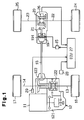
- a four-wheel drive vehicle according to a first embodiment of the present invention will now be described with reference to Figs. 1 to 4(b).
- the vehicle is normally in two-wheel drive. Specifically, the engine drives the front wheels in normal circumstances.
- the four-wheel drive vehicle has a drive source, which is an internal combustion engine 11 in this embodiment, and a transaxle 12.
- the transaxle 12 includes a transmission 121, a front differential 122, and a transfer 123.
- First and second front axles 13, 14 are coupled to the front differential 122.
- a left front wheel 16 is coupled to the first front axle 13.
- a right front wheel 17 is coupled to the second front axle 14. Power of the engine 11 is transmitted to the front wheels 16, 17 by the transmission 121, the front differential 122, and the front axles 13, 14.
- One end of a propeller shaft 18 is coupled to the transfer 123.
- the other end of the propeller shaft 18 is coupled to an electromagnetic clutch mechanism 19 of a multi-plate wet type. Power of the engine 11 is transmitted to the clutch mechanism 19 by the transmission 121, the transfer 123, and the propeller shaft 18.
- the clutch mechanism 19 is coupled to a rear differential 20 with a drive pinion 21.
- First and second rear axles 22, 23 are coupled to the rear differential 20.
- a left rear wheel 24 is coupled to the first rear axle 22.
- a right rear wheel 25 is coupled to the second rear axle 23.
- the transfer 123, the propeller shaft 18, the clutch mechanism 19, the drive pinion 21, the rear differential 20, and the rear axles 22, 23 form a power transmission system, which extends from the engine 11 to the rear wheels 24, 25.
- the clutch mechanism 19 includes an electromagnetic coil 191 and clutch disks (not shown), which are coupled to and separated from one another. When the electromagnetic coil 191 is excited, the clutch disks are engaged, and power is transmitted from the propeller shaft 18 to the drive pinion 21. The power transmitted to the drive pinion 21 is transmitted to the rear wheels 24, 25 through the rear differential 20 and the rear axles 22, 23.
- the distribution ratio of the power transmitted from the engine 11 to the drive pinion 21 through Lhe propeller shaft 18 is determined by the frictional force among the clutch disks.
- the power transmitted to the drive pinion 21 is increased as the frictional force among the clutch disks is increased.
- the frictional force among the clutch disks is determined by the amount of the current supplied to the electromagnetic coil 191. Therefore, if the current supplied to the electromagnetic coil 191 is controlled, the power distribution ratio to the front wheels 16, 17 and the rear wheels 24, 25 will be controlled.
- the clutch mechanism 19 is a transmission apparatus capable of varying the ratio of the power transmitted from the engine 11 to the front wheels 16, 17 and the rear wheels 24, 25.
- a temperature detecting device which is a temperature sensor 26 in this embodiment, is attached to the rear differential.
- the temperature sensor 26 detects the temperature of lubricating oil that is stored in and lubricates the rear differential 20.
- the temperature sensor 26 is connected an electronic control unit (ECU) 27 for distributing power. The information detected by the temperature sensor 26 is sent to the ECU 27.
- the ECU 27 is connected to a vehicle speed sensor 28 and a throttle opening sensor 29. The value detected by the vehicle speed sensor 28 and the value detected by the throttle opening sensor 29 are sent to the ECU 27.
- the ECU 27 includes a CPU 271, a ROM 272, a RAM 273, and input-output circuit 274.
- the electromagnetic coil 191 of the clutch mechanism 19 is electrically connected to a drive circuit 15.
- the drive circuit 15, the temperature sensor 26, the vehicle speed sensor 28, and the throttle opening sensor 29 are connected to the input-output circuit 274.
- the ECU 27 controls the current to the electromagnetic coil 191 by means of the drive circuit 15. The current is duty controlled.
- the duty ratio As the duty ratio is increased, the frictional force of the clutch mechanism 19 is increased. Accordingly, ratio of power transmission at the clutch 19 is increased. In other words, the power distribution ratio to the rear wheels 24, 25 is increased. When the duty ratio is 100%, the power distribution ratio is maximized. When the duty ratio is 0%, the power distribution ratio is zero. As the power distribution ratio to the rear wheels 24, 25 is increased, the load on the rear differential 20 is increased. As a result, the temperature of oil lubricating the rear differential 20 is increased. As the power distribution ratio to the rear wheels 24, 25 is decreased, the load on the rear differential 20 is decreased. As a result, the temperature of oil lubricating the rear differential 20 is decreased.
- the ROM 272 stores a control program and map data for controlling the current to the electromagnetic coil 191 of the clutch mechanism 19.
- a flowchart of Fig. 3 schematically shows a control program stored in the ROM 272.
- the CPU 271 executes various computations for controlling the current to the clutch mechanism 19 based on a control program and map data stored in the ROM 272.
- the RAM 273 temporarily stores computation results of the CPU 271 and stores various data.
- the map data stored in the ROM 272 is related to the duty ratio of the current supplied to the electromagnetic coil 191.
- the map data is defined by using the Lhrottle opening degree and the vehicle speed as parameters.
- the map data includes a first map D1 shown in Fig. 4(a) and a second map D2 shown in Fig. 4(b).
- the first map D1 is used in normal conditions and the second map D2 is used in a specific state.
- V1, V2, V3, V4, ... show the vehicle speed
- ⁇ 1, ⁇ 2, ⁇ 3, ⁇ 4, ... show the throttle opening degree.
- R00, R10, R20..., R01, R11, R21..., (hereinafter referred to as Rmn, in which m and n are integers equal to or greater than zero)
- K00, K10, K20..., K01, K11, K21 (hereinafter referred to as Kmn, in which m and n are integers equal to or greater than zero) represent duty ratios (see Fig. 4(b)).
- the ECU 27 selects one of the first and second maps D1, D2 based on the information detected by the temperature sensor 26.
- the ECU 27 controls the current to the electromagnetic coil 191 based on the information detected by the vehicle speed sensor 28, the information detected by the throttle opening sensor 29, and the map data.
- the power distribution control will now be described with reference to the flowchart of Fig. 3.
- the ECU 27 samples the detected information from the temperature sensor 26, the vehicle speed sensor 28, and the throttle opening sensor 29 at predetermined time intervals.
- step S1 the ECU 27 compares the temperature Tx detected by the temperature sensor 26 with a first reference temperature T1.
- the first reference temperature T1 is an index to indicate that the temperatures of the oil lubricating the rear differential 20 above it are undesirable.
- the first reference temperature T1 is obtained through experiments or is theoretically computed.
- the first reference temperature T1 is stored in the ROM 272. If a formula Tx ⁇ T1 is satisfied, the ECU 27 proceeds to step So and performs a normal control by using the first map D1. If a formula Tx ⁇ T1 is satisfied, the ECU 27 proceeds to step S2 and compares the detected temperature Tx with a predetermined second reference temperature T2 (T2 > T1).
- the second reference temperature T2 is an index to indicate that a temperature increase of the oil lubricating the rear differential 20 above it likely to cause a lubrication failure.
- the second reference temperature T2 is obtained through experiments or is theoretically computed.
- the second reference temperature T2 is stored in the ROM 272.
- the ECU 27 compares a first duration t1 in which the formula T2 > Tx ⁇ T1 is satisfied with a first reference duration ⁇ .
- the first reference duration ⁇ is stored in the ROM 272. If a formula t1 ⁇ ⁇ is satisfied, the ECU 27 returns to step S1. If a formula t1 ⁇ ⁇ is satisfied, the ECU 27 proceeds to step S4 and performs the specified control by using the second map D2.
- the ECU 27 compares the detected temperature Tx with a first return permission temperature To in step S5.
- the first return permission temperature To is an index to indicate that the control is permitted to return to the normal control after the temperature of the lubricating oil drops from the state represented by the formula T2 > Tx ⁇ T1.
- the first return permission temperature To is obtained through experiments or is theoretically computed.
- the first return permission temperature To is stored in the ROM 272. If a formula To ⁇ Tx is satisfied, the ECU 27 proceeds to step So and performs the normal control by using the first map D1.
- step S6 the ECU 27 compares a second duration t2 in which the formula Tx ⁇ T2 is satisfied with a second reference duration ⁇ . If a formula t2 ⁇ ⁇ is satisfied, the ECU 2 returns to step S2. If a formula t2 ⁇ ⁇ is satisfied, the ECU 27 proceeds to step S7. In step S7, the ECU 27 stops the current to the electromagnetic coil 191 to start the two-wheel drive, in which only the front wheels 16, 17 are driven. During the two-wheel drive, the ECU 27 compares the detected temperature Tx with a predetermined second return permission temperature T3 in step S8.
- the second return permission temperature T3 is an index to indicate that the control is permitted to return to the normal control when the temperature of the lubricating oil drops from the state represented by the formula Tx ⁇ T2.
- the second return permission temperature T3 is obtained through experiments or is theoretically computed.
- the second return permission temperature T3 is stored in the ROM 272. If a formula T3 ⁇ Tx is satisfied, the ECU 27 proceeds to step So and performs the normal control by using the first map D1.
- the ECU 27 decreases the power distribution ratio at the clutch mechanism 19.
- This embodiment provides the following advantages.
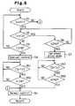
- the second embodiment will now be described with reference to Fig. 5.
- the structure of the power distribution control apparatus according to this embodiment is the same as that of the embodiment shown in Figs. 1 to 4(b). This embodiment is different from the embodiment of Figs. 1 to 4(b) in the control program for the power distribution.
- step S5 of Fig. 3 is replaced by steps S51 and S52
- step S8 of Fig. 3 is replaced by steps S81 and S82.
- step S4 that is, during the specific control using the second map D2
- the ECU 27 compares the detected temperature Tx with the first reference temperature T1 in step S51. If the detected temperature Tx is lower than the first reference temperature T1, the ECU 27 proceeds to step S52.
- step S52 the ECU 27 compares a duration s1 of the detected temperature Tx with a predetermined third reference duration ⁇ . If a formula s1 ⁇ ⁇ is satisfied, the ECU 1 returns to step S51. If a formula s1 ⁇ ⁇ is satisfied, the ECU 1 proceeds to step So. In step So, the ECU 27 performs the normal control by using the first map D1.
- step S7 the ECU 27 compares the detected temperature Tx with the predetermined second reference temperature T2 in step S81. If the detected temperature Tx is lower than the reference temperature T2, the ECU 27 proceeds to step S82. In step S82, the ECU 27 compares a duration s2 of the detected temperature Tx with a predetermined fourth reference duration ⁇ . If a formula s2 ⁇ ⁇ is satisfied, the ECU 2 returns to step S7. If a formula S2 ⁇ ⁇ is satisfied, the ECU 27 proceeds to step So arid shifts the control to the normal control.
- the first reference duration ⁇ is determined such that hunting at the first reference temperature T1 is avoided.
- the second reference duration ⁇ is determined such that hunting at the second reference temperature T2 is avoided. Therefore, in this embodiment, hunting at both reference temperatures T1 and T2 is prevented.
- the control may be immediately shifted from the normal control to the specific control when the detected temperature of the lubricating oil reaches the first reference temperature T1.
- the control may be immediately shifted from the normal control to the two-wheel drive when the detected temperature of the lubricating oil reaches the second reference temperature T2.
- the power transmission distribution ratio at the clutch mechanism 19 may be decreased to zero. That is, the current to the electromagnetic coil 191 of the clutch 19 may be stopped so that the control is shifted to the two-wheel drive.
- the power distribution control may be performed based on a power distribution control program that includes steps S5, S8 of the flowchart of the embodiment shown in Figs. 1 to 4(b) and steps S51, S81 of the flowchart of the embodiment shown in Fig. 5.
- the difference (differential rotation speed) between the average rotation speed of the front wheels 16, 17 and the average rotation speed of the rear wheels 24, 25 may be used.
- wheel speed sensors are needed for separately detecting the rotation speed of the front wheels 16, 17 and the rotation speed of the rear wheels 24, 25.
- Temperature may be detected at the transfer 123. Specifically, the temperature of oil that is stored in and lubricates the transfer 123 may be detected.
- the present invention may be applied to a FR type or RR type four-wheel-drive vehicle, which drives the rear wheels during the two-wheel drive.
- the present invention may be applied to vehicles other than four-wheel-drive vehicles.
- a vehicle has a transmission apparatus (19) that changes the distribution of power transmitted from a power source (11) to a plurality of wheels (16, 17, 24, 25).
- the method for distributing power of the vehicle includes detecting the temperature (Tx) of a part located on a power transmission path between the power source (11) and a wheel (16, 17, 24, 25) to which power is transmitted from the power source (11) through the transmission apparatus (19), the heat of the part being increased as the power distribution ratio is increased; determining that the current state is a specific state in which the detected temperature (Tx) reaches a previously set first reference temperature; and controlling the transmission apparatus (19) to lower the power distribution ratio to the wheel (16, 17, 24, 25) from the transmission apparatus (19) when the current state is determined to the specified state.
Landscapes
- Engineering & Computer Science (AREA)
- Chemical & Material Sciences (AREA)
- Combustion & Propulsion (AREA)
- Transportation (AREA)
- Mechanical Engineering (AREA)
- Arrangement And Driving Of Transmission Devices (AREA)
Abstract
Description
- The present invention relates to a power distribution method and a power distribution control apparatus for vehicles.
- A standby four-wheel drive system is known in the art. The standby four-wheel drive system controls distribution of power to the front wheels and the rear wheels according to the driving state of a vehicle. When all the four wheels of a four-wheel drive vehicle are being driven, some of the power generated by the engine is transmitted to the rear wheels by a transmission apparatus, which is capable of changing the power distribution ratio to the front wheels and the rear wheels.
- A typical transmission apparatus includes an electromagnetic clutch mechanism of a multi-plate wet type. The frictional force among the clutch disks of the electromagnetic clutch mechanism is varied in accordance with the amount of the current supplied to a magnet coil. As the frictional force is increased, the ratio of the power distribution to the rear wheels is increased.
- When the power distribution to the rear wheels is increased, the load on the transfer located between the engine and the transmission apparatus, and the load on the rear differential located between the transmission apparatus and the rear wheels are increased. Accordingly, the temperature of the oil lubricating the transfer and the temperature of the oil lubricating the rear differential are likely to increase. When excessively heated, the lubrication performance of the lubricating oil deteriorates.
- Accordingly, it is an objective of the present invention to prevent excessive temperature increases at a part that is heated as the ratio of power distribution to vehicle rear wheels is increased.
- To achieve the above objects, one aspect of the present invention provides a method for distributing power of a vehicle. The vehicle has a transmission apparatus that changes the distribution ratio of power transmitted from a power source to a plurality of wheels. The method includes detecting the temperature of a part located on a power transmission path between the power source and a wheel to which power is transmitted from the power source through the transmission apparatus, the heat of the part being increased as the power distribution ratio is increased; determining that the current state is a specitic state in which the detected temperature reaches a previously set first reference temperature; and controlling the transmission apparatus to lower the power distribution ratio to the wheel from the transmission apparatus when the current state is determined to the specified state.
- Another aspect of the present invention provides a power distribution control apparatus for a vehicle. The control apparatus includes a transmission apparatus that changes the distribution ratio of power transmitted from a power source to a plurality of wheels. The control apparatus has a detector and an electronic control unit. The detector detects the temperature of a part located on a power transmission path between the power source and a wheel to which power is transmitted from the power source through the transmission apparatus, the heat of the part being increased as the power distribution ratio at the transmission apparatus is increased. The control unit controls the power distribution ratio at the transmission apparatus thereby controlling the distribution ratio of power to the wheels. When the current state is a specific state in which the temperature detected by the detector is equal to or higher that a previously set first reference temperature, the control unit controls the transmission apparatus to decrease the power distribution ratio.
- Other aspects and advantages of the invention will become apparent from the following description, taken in conjunction with the accompanying drawings, illustrating by way of example the principles of the invention.
- The invention, together with objects and advantages thereof, may best be understood by reference to the following description of the presently preferred embodiments together with the accompanying drawings in which:
- Fig. 1 is a schematic plan view showing a four-wheel drive vehicle according to a first embodiment of the present invention;
- Fig. 2 is a diagram showing a control circuit of the first embodiment;
- Fig. 3 is a flowchart showing a power distribution control of the first embodiment;
- Fig. 4(a) is a map of data used in the power distribution of a normal control according to the first embodiment;
- Fig. 4(b) is a map of data used in the power distribution of a specified control according to the first embodiment; and
- Fig. 5 is a flowchart showing a power distribution control according to a second embodiment.
-
- A four-wheel drive vehicle according to a first embodiment of the present invention will now be described with reference to Figs. 1 to 4(b). The vehicle is normally in two-wheel drive. Specifically, the engine drives the front wheels in normal circumstances.
- As shown in Fig. 1, the four-wheel drive vehicle has a drive source, which is an
internal combustion engine 11 in this embodiment, and atransaxle 12. Thetransaxle 12 includes atransmission 121, afront differential 122, and atransfer 123. First and secondfront axles front differential 122. A leftfront wheel 16 is coupled to the firstfront axle 13. A rightfront wheel 17 is coupled to the secondfront axle 14. Power of theengine 11 is transmitted to thefront wheels transmission 121, thefront differential 122, and thefront axles - One end of a
propeller shaft 18 is coupled to thetransfer 123. The other end of thepropeller shaft 18 is coupled to anelectromagnetic clutch mechanism 19 of a multi-plate wet type. Power of theengine 11 is transmitted to theclutch mechanism 19 by thetransmission 121, thetransfer 123, and thepropeller shaft 18. Theclutch mechanism 19 is coupled to arear differential 20 with adrive pinion 21. First and secondrear axles rear differential 20. A leftrear wheel 24 is coupled to the firstrear axle 22. A rightrear wheel 25 is coupled to the secondrear axle 23. In this embodiment, thetransfer 123, thepropeller shaft 18, theclutch mechanism 19, thedrive pinion 21, therear differential 20, and therear axles engine 11 to therear wheels - The
clutch mechanism 19 includes anelectromagnetic coil 191 and clutch disks (not shown), which are coupled to and separated from one another. When theelectromagnetic coil 191 is excited, the clutch disks are engaged, and power is transmitted from thepropeller shaft 18 to thedrive pinion 21. The power transmitted to thedrive pinion 21 is transmitted to therear wheels rear differential 20 and therear axles - The distribution ratio of the power transmitted from the
engine 11 to thedrive pinion 21 throughLhe propeller shaft 18 is determined by the frictional force among the clutch disks. The power transmitted to thedrive pinion 21 is increased as the frictional force among the clutch disks is increased. The frictional force among the clutch disks is determined by the amount of the current supplied to theelectromagnetic coil 191. Therefore, if the current supplied to theelectromagnetic coil 191 is controlled, the power distribution ratio to thefront wheels rear wheels clutch mechanism 19 is a transmission apparatus capable of varying the ratio of the power transmitted from theengine 11 to thefront wheels rear wheels - A temperature detecting device, which is a
temperature sensor 26 in this embodiment, is attached to the rear differential. Thetemperature sensor 26 detects the temperature of lubricating oil that is stored in and lubricates therear differential 20. Thetemperature sensor 26 is connected an electronic control unit (ECU) 27 for distributing power. The information detected by thetemperature sensor 26 is sent to theECU 27. The ECU 27 is connected to avehicle speed sensor 28 and athrottle opening sensor 29. The value detected by thevehicle speed sensor 28 and the value detected by thethrottle opening sensor 29 are sent to theECU 27. - As shown in Fig. 2, the
ECU 27 includes aCPU 271, aROM 272, aRAM 273, and input-output circuit 274. Theelectromagnetic coil 191 of theclutch mechanism 19 is electrically connected to adrive circuit 15. Thedrive circuit 15, thetemperature sensor 26, thevehicle speed sensor 28, and thethrottle opening sensor 29 are connected to the input-output circuit 274. TheECU 27 controls the current to theelectromagnetic coil 191 by means of thedrive circuit 15. The current is duty controlled. - As the duty ratio is increased, the frictional force of the
clutch mechanism 19 is increased. Accordingly, ratio of power transmission at the clutch 19 is increased. In other words, the power distribution ratio to therear wheels rear wheels rear wheels - The
ROM 272 stores a control program and map data for controlling the current to theelectromagnetic coil 191 of theclutch mechanism 19. A flowchart of Fig. 3 schematically shows a control program stored in theROM 272. TheCPU 271 executes various computations for controlling the current to theclutch mechanism 19 based on a control program and map data stored in theROM 272. TheRAM 273 temporarily stores computation results of theCPU 271 and stores various data. - The map data stored in the
ROM 272 is related to the duty ratio of the current supplied to theelectromagnetic coil 191. The map data is defined by using the Lhrottle opening degree and the vehicle speed as parameters. The map data includes a first map D1 shown in Fig. 4(a) and a second map D2 shown in Fig. 4(b). The first map D1 is used in normal conditions and the second map D2 is used in a specific state. As shown in Figs. 4(a) and 4(b), V1, V2, V3, V4, ... show the vehicle speed, and 1, 2, 3, 4, ... show the throttle opening degree. R00, R10, R20..., R01, R11, R21..., (hereinafter referred to as Rmn, in which m and n are integers equal to or greater than zero), and K00, K10, K20..., K01, K11, K21 (hereinafter referred to as Kmn, in which m and n are integers equal to or greater than zero) represent duty ratios (see Fig. 4(b)).When Rmn is not zero, a formula Rmn > Kmn is satisfied. - The
ECU 27 selects one of the first and second maps D1, D2 based on the information detected by thetemperature sensor 26. TheECU 27 controls the current to theelectromagnetic coil 191 based on the information detected by thevehicle speed sensor 28, the information detected by thethrottle opening sensor 29, and the map data. - The power distribution control will now be described with reference to the flowchart of Fig. 3. The
ECU 27 samples the detected information from thetemperature sensor 26, thevehicle speed sensor 28, and thethrottle opening sensor 29 at predetermined time intervals. - In step S1, the
ECU 27 compares the temperature Tx detected by thetemperature sensor 26 with a first reference temperature T1. The first reference temperature T1 is an index to indicate that the temperatures of the oil lubricating the rear differential 20 above it are undesirable. The first reference temperature T1 is obtained through experiments or is theoretically computed. The first reference temperature T1 is stored in theROM 272. If a formula Tx < T1 is satisfied, theECU 27 proceeds to step So and performs a normal control by using the first map D1. If a formula Tx ≥ T1 is satisfied, theECU 27 proceeds to step S2 and compares the detected temperature Tx with a predetermined second reference temperature T2 (T2 > T1). The second reference temperature T2 is an index to indicate that a temperature increase of the oil lubricating the rear differential 20 above it likely to cause a lubrication failure. The second reference temperature T2 is obtained through experiments or is theoretically computed. The second reference temperature T2 is stored in theROM 272. In step S3, theECU 27 compares a first duration t1 in which the formula T2 > Tx ≥ T1 is satisfied with a first reference duration α. The first reference duration α is stored in theROM 272. If a formula t1 < α is satisfied, theECU 27 returns to step S1. If a formula t1 ≥ α is satisfied, theECU 27 proceeds to step S4 and performs the specified control by using the second map D2. - During the specified control using the second map D2, the
ECU 27 compares the detected temperature Tx with a first return permission temperature To in step S5. The first return permission temperature To is an index to indicate that the control is permitted to return to the normal control after the temperature of the lubricating oil drops from the state represented by the formula T2 > Tx ≥ T1. The first return permission temperature To is obtained through experiments or is theoretically computed. The first return permission temperature To is stored in theROM 272. If a formula To ≥ Tx is satisfied, theECU 27 proceeds to step So and performs the normal control by using the first map D1. - If a formula Tx ≥ T2 is satisfied, the
ECU 27 proceeds to sLep S6. In step S6, theECU 27 compares a second duration t2 in which the formula Tx ≥ T2 is satisfied with a second reference duration γ. If a formula t2 < γ is satisfied, theECU 2 returns to step S2. If a formula t2 ≥ γ is satisfied, theECU 27 proceeds to step S7. In step S7, theECU 27 stops the current to theelectromagnetic coil 191 to start the two-wheel drive, in which only thefront wheels ECU 27 compares the detected temperature Tx with a predetermined second return permission temperature T3 in step S8. The second return permission temperature T3 is an index to indicate that the control is permitted to return to the normal control when the temperature of the lubricating oil drops from the state represented by the formula Tx ≥ T2. The second return permission temperature T3 is obtained through experiments or is theoretically computed. The second return permission temperature T3 is stored in theROM 272. If a formula T3 ≥ Tx is satisfied, theECU 27 proceeds to step So and performs the normal control by using the first map D1. - If the temperature detected by the
temperature sensor 26 reaches a predetermined reference temperature, theECU 27 decreases the power distribution ratio at theclutch mechanism 19. - This embodiment provides the following advantages.
- (1-1) If the temperature of the oil lubricating the rear
differential 20 has not reached the first reference
temperature T1, the normal control using the first map D1 is
executed. If the temperature of the oil lubricating the rear
differential 20 reaches the first reference temperature T1 and
this temperature state has continued over the first reference
duration α, that is, if the temperature is in a specific
state, the normal control in which the four wheels are driven,
likely to further increase the temperature of the oil
lubricating the
rear differential 20. When the specific state occurs, the control using the second map D2 is executed. When the vehicle speed and the throttle opening degree are constant, the duty ratio Kmn on the second map D2, which is not zero, is less than the duty ratio Rmn on the first map D1. Therefore, if the control is shifted from the one using the first map D1 to the one using the second map D2, the power transmission distribution ratio at theclutch mechanism 19 is lowered to the power transmission distribution ratio for the specific state. Accordingly, the power distribution ratio to therear wheels - (1-2) If the temperature of the oil lubricating the rear
differential 20 reaches the second reference temperature T2
and this temperature state has continued over the second
reference duration γ, that is, if the temperature is in the
specific state, the normal control using the first map D1 is
likely to excessively heat the oil lubricating the
rear differential 20. However, in this embodiment, the current to theelectromagnetic coil 191 is stopped in the specific state. Accordingly, the power transmission distribution ratio at theclutch mechanism 19 is lowered to zero, and the power distribution ratio to therear wheels clutch mechanism 19 is zero readily decreases the temperature of the rear differential 20 to the second reference temperature T2. Such decrease in the power transmission distribution ratio to zero prevents the rear differential 20 from being excessively heated, that is, prevents the oil lubricating the rear differential 20 from being excessively heated. - (1-3) The first return permission temperature To is an index to indicate that the control is permitted to return to the normal control after the temperature of the lubricating oil drops from the state represented by the formula Tx ≥ T1. If the control is returned to the normal control when the temperature of the lubricating oil drops below the first reference temperature T1, hunting of the lubricating oil temperature is likely to occur. That is, the lubricating oil temperature is likely to repeatedly surpass and drop blow the first reference temperature T1 in a short time. However, since the first return permission temperature To, which is lower than the first reference temperature T1, is used as an index to return the control to the normal control, such hunting is prevented.
- (1-4) The second return permission temperature T3 is an index to indicate that the control is permitted to return to the normal control after the temperature of the lubricating oil drops from the state represented by the formula Tx ≥ T2. If the control is returned to the normal control when the temperature of the lubricating oil drops below the second reference temperature T2, hunting of the lubricating oil temperature is likely to occur. That is, the lubricating oil temperature is likely to repeatedly surpass and drop blow the second reference temperature T2 in a short time. However, since the second return permission temperature T3, which is lower than the second reference temperature T2, is used as an index to return the control to the normal control, such hunting is prevented.
- (1-5) If the state in which the temperature Tx of the lubricating oil is equal to or higher than T1 and lower than T2 continues over the first reference duration α, the control is shifted from the normal control using the first map D1 to the specified control using the second map D2. If the state in which a formula T2 > Tx ≥ T1 is satisfied continues over the first reference duration α (for example, several tens of seconds), the temperature of the lubricating oil is highly likely to increase further. Even if the temperature Tx of the lubricating oil momentarily surpasses T1, it is not certain that the lubricating oil temperature will increase further. Therefore, if the control is shifted from the normal control to the specified control as soon as the lubricating oil temperature Tx reaches T1, the shifting of the control may be meaningless. Meaningless shifting hinders the power distribution ratio from being optimized. Therefore, using the first reference duration α is effective to determine whether the lubricating oil temperature will continue to increase.
- (1-6) When the lubricating oil temperature Tx is equal to or higher than T2 over the second reference duration γ, the two-wheel drive is started. If the state in which a formula Tx ≥ T2 is satisfied continues over the second reference duration γ (for example, several tens of seconds), the temperature of the lubricating oil is highly likely to increase further. Even if the temperature Tx of the lubricating oil momentarily surpasses T2, it is not certain that the lubricating oil temperature will increase further. Therefore, if the control is shifted from the normal control to the two-wheel drive as soon as the lubricating oil temperature Tx reaches T2, the shifting of the control may be meaningless. Meaningless shifting hinders the power distribution ratio from being optimized. Therefore, using the second reference duration γ is effective to determine whether the lubricating oil temperature will continue to increase.
-
- The second embodiment will now be described with reference to Fig. 5. The structure of the power distribution control apparatus according to this embodiment is the same as that of the embodiment shown in Figs. 1 to 4(b). This embodiment is different from the embodiment of Figs. 1 to 4(b) in the control program for the power distribution.
- In this embodiment, step S5 of Fig. 3 is replaced by steps S51 and S52, and step S8 of Fig. 3 is replaced by steps S81 and S82. After step S4, that is, during the specific control using the second map D2, the
ECU 27 compares the detected temperature Tx with the first reference temperature T1 in step S51. If the detected temperature Tx is lower than the first reference temperature T1, theECU 27 proceeds to step S52. In step S52, theECU 27 compares a duration s1 of the detected temperature Tx with a predetermined third reference duration β. If a formula s1 < β is satisfied, theECU 1 returns to step S51. If a formula s1 ≥ β is satisfied, theECU 1 proceeds to step So. In step So, theECU 27 performs the normal control by using the first map D1. - After step S7, that is, during the two-wheel drive, the
ECU 27 compares the detected temperature Tx with the predetermined second reference temperature T2 in step S81. If the detected temperature Tx is lower than the reference temperature T2, theECU 27 proceeds to step S82. In step S82, theECU 27 compares a duration s2 of the detected temperature Tx with a predetermined fourth reference duration δ. If a formula s2 < δ is satisfied, theECU 2 returns to step S7. If a formula S2 ≥ δ is satisfied, theECU 27 proceeds to step So arid shifts the control to the normal control. - The first reference duration β is determined such that hunting at the first reference temperature T1 is avoided. The second reference duration δ is determined such that hunting at the second reference temperature T2 is avoided. Therefore, in this embodiment, hunting at both reference temperatures T1 and T2 is prevented.
- It should be apparent to those skilled in the art that the present invention may be embodied in many other specific forms without departing from the spirit or scope of the invention. Particularly, it should be understood that the invention may be embodied in the following forms.
- The control may be immediately shifted from the normal control to the specific control when the detected temperature of the lubricating oil reaches the first reference temperature T1.
- The control may be immediately shifted from the normal control to the two-wheel drive when the detected temperature of the lubricating oil reaches the second reference temperature T2.
- During the specific state, in which the detected temperature of the lubricating oil is equal to or above the first reference temperature T1, the power transmission distribution ratio at the
clutch mechanism 19 may be decreased to zero. That is, the current to theelectromagnetic coil 191 of the clutch 19 may be stopped so that the control is shifted to the two-wheel drive. - The power distribution control may be performed based on a power distribution control program that includes steps S5, S8 of the flowchart of the embodiment shown in Figs. 1 to 4(b) and steps S51, S81 of the flowchart of the embodiment shown in Fig. 5.
- In this case, when the formula Tx ≤ To is satisfied or when formulas Tx < T1 and s1 ≥ β are satisfied, the control is shifted from the specified control to the normal control. Also, when the formula Tx ≤ T3 is satisfied or when formulas Tx < T2 and s2 ≥ δ are satisfied, the control is shifted from the specified control to the two-wheel drive.
- As a parameter for the first and second maps, the difference (differential rotation speed) between the average rotation speed of the
front wheels rear wheels - In this case, wheel speed sensors are needed for separately detecting the rotation speed of the
front wheels rear wheels - Temperature may be detected at the
transfer 123. Specifically, the temperature of oil that is stored in and lubricates thetransfer 123 may be detected. - The present invention may be applied to a FR type or RR type four-wheel-drive vehicle, which drives the rear wheels during the two-wheel drive.
- The present invention may be applied to vehicles other than four-wheel-drive vehicles.
- Therefore, the present examples and embodiments are to be considered as illustrative and not restrictive and the invention is not to be limited to the details given herein, but may be modified within the scope and equivalence of the appended claims.
- A vehicle has a transmission apparatus (19) that changes the distribution of power transmitted from a power source (11) to a plurality of wheels (16, 17, 24, 25). The method for distributing power of the vehicle includes detecting the temperature (Tx) of a part located on a power transmission path between the power source (11) and a wheel (16, 17, 24, 25) to which power is transmitted from the power source (11) through the transmission apparatus (19), the heat of the part being increased as the power distribution ratio is increased; determining that the current state is a specific state in which the detected temperature (Tx) reaches a previously set first reference temperature; and controlling the transmission apparatus (19) to lower the power distribution ratio to the wheel (16, 17, 24, 25) from the transmission apparatus (19) when the current state is determined to the specified state.
Claims (19)
- A method for distributing power of a vehicle, wherein the vehicle has a transmission apparatus (19) that changes the distribution of power transmitted from a power source (11) to a plurality of wheels (16, 17, 24, 25), the method being characterized by:detecting the temperature (Tx) of a part located on a power transmission path between the power source (11) and a wheel (16, 17, 24, 25) to which power is transmitted from the power source (11) through the transmission apparatus (19), the heat of the part being increased as the power distribution ratio is increased;determining that the current state is a specific state in which the detected temperature (Tx) reaches a previously set first reference temperature; andcontrolling the transmission apparatus (19) to lower the power distribution ratio to the wheel (16, 17, 24, 25) from the transmission apparatus (19) when the current state is determined to the specified state.
- The method according to claim 1, characterized in that the specific state is a state in which the detected temperature (Tx) has been equal to or higher than the first reference temperature (T1) for a previously set first reference duration (α).
- The method according to claims 1 or 2, characterized in that, when the current state is determined to be the specific state, the power distribution ratio is decreased to a predetermined value that is greater than zero, and wherein, when the detected temperature (Tx) reaches a second reference temperature (T2) that is higher than the first reference temperature (T1), the power distribution ratio is set to zero.
- The method according to claim 3, wherein the predetermined value is changed in accordance with the driving state of the vehicle.
- The method according to claim 3, characterized in that the power distribution ratio is set to zero when the detected temperature (Tx) has been equal to or higher than the second reference temperature (T2) for a previously set second reference duration (γ).
- The method according to any one of claims 1 to 5, characterized in that the detecting the temperature includes detecting the temperature of a differential (20) located between the transmission apparatus (19) and the wheel (16, 17, 24, 25) to which power is transmitted through the transmission apparatus (19).
- The method according to any one of claims 1 to 6, characterized in that the detecting the temperature includes detecting the temperature of a transfer (123) located between the power source (11) and the transmission apparatus (19).
- The method according to any one of claims 1 to 7, further being characterized by controlling the transmission apparatus (19) to return the current power distribution ratio to the power distribution ratio of the time before the power distribution ratio was decreased if, after the power distribution ratio is decreased, the detected temperature (Tx) becomes a permission temperature (T3) that is lower than the first reference temperature (T1).
- The method according to any one of claims 1 to 8, wherein the drive source is an engine, the engine having a throttle valve, wherein a plurality of maps for determining the power distribution ratio from the transmission apparatus to the wheels in accordance with the vehicle speed and the opening degree of the throttle valve are prepared, wherein the power distribution ratio to the wheels is changed by using a selected one of the maps, wherein the maps include a first map used in states other than the specified state and a second map used in the specified state, wherein, under the conditions with the same vehicle speed and the same throttle opening degree, the power distribution ratio based on the second map is less than the power distribution ratio based on the first map.
- A power distribution control apparatus for a vehicle, wherein the control apparatus includes a transmission apparatus (19) thaL changes the distribution of power transmitted from a power source (11) to a plurality of wheels (16, 17, 24, 25), the control apparatus being characterized by:a detector (26) for detecting the temperature of a part located on a power transmission path between the power source (11) and a wheel to which power is transmitted from the power source (11) through the transmission apparatus (19), the heat of the part being increased as the power distribution ratio at the transmission apparatus (19) is increased; andan electronic control unit (27), wherein the control unit (27) controls the power distribution ratio at the transmission apparatus (19) thereby controlling the distribution ratio of power to the wheels (16, 17, 24, 25), wherein, when the current state is a specific state in which the temperature (Tx) detected by the detector (26) is equal to or higher that a previously set first reference temperature (T1), the control unit (27) controls the transmission apparatus (19) to decrease the power distribution ratio.
- The apparatus according to claim 10, characterized in that the specific state is a state in which the detected temperature has been equal to or higher than the first reference temperature (T1) for a previously set first reference duration (α).
- The apparatus according to claims 10 or 11, characterized in that, when the current state is determined to be the specific state, the control unit (27) controls the transmission apparatus (19) to decrease the power distribution ratio to a predetermined value that is greater than zero, and wherein, when the detected temperature (Tx) reaches a second reference temperature (T2) that is higher than the first reference temperature (T1), the control unit (27) controls the transmission apparatus (19) to set the power distribution ratio to zero.
- The apparatus according to claim 12, wherein the predetermined value is changed in accordance with the driving state of the vehicle.
- The apparatus according to claim 12, characterized in that the power distribution ratio is set to zero when the detected temperature (Tx) has been equal to or higher than the second reference temperature (T2) for a previously set second reference duration (γ).
- The apparatus according to any one of claims 10 to 14, characterized in that the control unit (27) stores first data and second data (D1, D2), wherein, during the specified state, the control unit (27) controls the transmission apparatus (19) based on the second data (D2), and wherein, in any state other than the specific state, the control unit (27) controls the transmission apparatus (19) based on the first data (D1).
- The apparatus according to any one of claims 10 to 15, characterized in that the detector.(26) detects the temperature of a differential (20) located between the transmission apparatus (19) and the wheel (16, 17, 24, 25) to which power is transmitted through the transmission apparatus (19).
- The apparatus according to any one of claims 10 to 16, characterized in that the detector (26) detects the temperature of a transfer (123) located between the power source (11) and the transmission apparatus (19).
- The apparatus according to any one of claims 10 to 17, characterized in that, if, after the power distribution ratio is decreased, the detected temperature (Tx) becomes a permission temperature (T3) that is lower than the first reference temperature (T1), the control unit (27) controls the transmission apparatus (19) to return the current power distribution ratio to the power distribution ratio of the time before the power distribution ratio was decreased.
- The apparatus according to any one of claims 10 to 18, wherein the drive source is an engine (11), the engine (11) having a throttle valve, wherein the control unit has a plurality of maps for determining the power distribution ratio from the transmission apparatus (19) to the wheels in accordance with the vehicle speed and the opening degree of the throttle valve are prepared, wherein the control apparatus changes the power distribution ratio to the wheels by using a selected one of the maps, wherein the maps include a first map used in states other than the specified state and a second map used in the specified state, wherein, under the conditions with the same vehicle speed and the same throttle opening degree, the power distribution ratio based on the second map is less than the power distribution ratio based on the first map.
Applications Claiming Priority (2)
| Application Number | Priority Date | Filing Date | Title |
|---|---|---|---|
| JP2001334766 | 2001-10-31 | ||
| JP2001334766A JP2003136990A (en) | 2001-10-31 | 2001-10-31 | Driving force distribution method and driving force distribution control device for vehicle |
Publications (3)
| Publication Number | Publication Date |
|---|---|
| EP1308338A2 true EP1308338A2 (en) | 2003-05-07 |
| EP1308338A3 EP1308338A3 (en) | 2004-10-13 |
| EP1308338B1 EP1308338B1 (en) | 2007-08-01 |
Family
ID=19149852
Family Applications (1)
| Application Number | Title | Priority Date | Filing Date |
|---|---|---|---|
| EP02024195A Expired - Lifetime EP1308338B1 (en) | 2001-10-31 | 2002-10-30 | Power distribution method and power distribution control apparatus for vehicle |
Country Status (4)
| Country | Link |
|---|---|
| US (1) | US6752742B2 (en) |
| EP (1) | EP1308338B1 (en) |
| JP (1) | JP2003136990A (en) |
| DE (1) | DE60221479T2 (en) |
Cited By (6)
| Publication number | Priority date | Publication date | Assignee | Title |
|---|---|---|---|---|
| EP1749726A2 (en) | 2005-08-02 | 2007-02-07 | Jtekt Corporation | Drive force distribution device and method for distributing drive force |
| EP1749725A3 (en) * | 2005-08-02 | 2007-07-04 | Jtekt Corporation | Drive force distribution device and method for distributing drive force |
| EP1495901A3 (en) * | 2003-07-09 | 2007-09-05 | Jtekt Corporation | Drive power transmission control device |
| DE102008026554A1 (en) * | 2008-06-03 | 2009-12-10 | Magna Powertrain Ag & Co Kg | Method for controlling a coupling unit |
| DE102009032265A1 (en) | 2009-07-08 | 2011-01-13 | Magna Powertrain Ag & Co Kg | Method for protecting wheel coupling, involves arranging wheel coupling in drive train of motor vehicle, where failure of sensors, is determined, and substitute value is determined for rotation speed value of utilization factor |
| GB2488243A (en) * | 2011-02-18 | 2012-08-22 | Land Rover Uk Ltd | Vehicle having an auxiliary driveline controlled so as to reduce mode chattering |
Families Citing this family (11)
| Publication number | Priority date | Publication date | Assignee | Title |
|---|---|---|---|---|
| US7630812B2 (en) * | 2004-02-09 | 2009-12-08 | Ford Global Technologies, Llc | Method and system for controlling a transfer case clutch to protect against excessive heat |
| US7448977B2 (en) * | 2005-10-21 | 2008-11-11 | Ford Global Technologies, Llc | Motor vehicle transaxle having a differential mechanism controlled by an on-demand clutch |
| US7309301B2 (en) * | 2005-10-21 | 2007-12-18 | Ford Global Technologies, Llc | Transaxle having a differential mechanism and on-demand transfer clutch |
| ES2362238T3 (en) * | 2006-02-03 | 2011-06-30 | Eaton Corporation | TRACTION CONTROL AND SIDE DEVIATION WITH IMPROVED STABILITY, USING AN ELETRONICALLY CONTROLLED DIFFERENTIAL WITH LIMITED SLIDE. |
| JP5768363B2 (en) * | 2010-11-26 | 2015-08-26 | 株式会社ジェイテクト | Driving force distribution device |
| JP5789970B2 (en) * | 2010-12-07 | 2015-10-07 | 株式会社ジェイテクト | Driving force distribution device |
| GB2488156A (en) | 2011-02-18 | 2012-08-22 | Land Rover Uk Ltd | Vehicle and method for preventing switching between drive modes |
| DE102011111912A1 (en) * | 2011-08-30 | 2012-02-02 | Daimler Ag | Method for calculating temperature of oil in vehicle axle, particularly rear axle, involves computing heat flow in oil of engine of vehicle as function of engine torque and engine speed |
| JP6413454B2 (en) * | 2014-08-07 | 2018-10-31 | 株式会社ジェイテクト | Control device and control method for differential limiting device |
| US11802613B1 (en) * | 2022-06-21 | 2023-10-31 | Deere & Company | Locking differential energy management for work vehicles |
| US12311905B2 (en) | 2022-06-21 | 2025-05-27 | Deere & Company | Work vehicle brake energy management system |
Family Cites Families (7)
| Publication number | Priority date | Publication date | Assignee | Title |
|---|---|---|---|---|
| GB1411283A (en) * | 1972-06-21 | 1975-10-22 | Gkn Transmissions Ltd | Four-wheel-drive vehicles |
| DE3643831A1 (en) * | 1986-12-20 | 1988-07-07 | Deere & Co | DRIVE SYSTEM FOR THE WHEELS OF TWO WHEEL COUPLES |
| JP2541811B2 (en) * | 1987-03-31 | 1996-10-09 | 本田技研工業株式会社 | 4-wheel drive vehicle |
| JPH0231935A (en) * | 1988-07-18 | 1990-02-01 | Toyota Motor Corp | Control method for front and rear wheel differential control clutch |
| JP2501514Y2 (en) * | 1989-03-31 | 1996-06-19 | トヨタ自動車株式会社 | Two-wheel / four-wheel switching control device for four-wheel drive vehicle |
| JPH04339028A (en) * | 1991-01-23 | 1992-11-26 | Nissan Motor Co Ltd | Transmission torque characteristic changeover control device |
| JP3791625B2 (en) * | 1995-08-11 | 2006-06-28 | 日産自動車株式会社 | Four-wheel drive control device for vehicle |
-
2001
- 2001-10-31 JP JP2001334766A patent/JP2003136990A/en active Pending
-
2002
- 2002-10-30 DE DE60221479T patent/DE60221479T2/en not_active Expired - Lifetime
- 2002-10-30 EP EP02024195A patent/EP1308338B1/en not_active Expired - Lifetime
- 2002-10-31 US US10/284,351 patent/US6752742B2/en not_active Expired - Fee Related
Non-Patent Citations (1)
| Title |
|---|
| None |
Cited By (14)
| Publication number | Priority date | Publication date | Assignee | Title |
|---|---|---|---|---|
| EP1495901A3 (en) * | 2003-07-09 | 2007-09-05 | Jtekt Corporation | Drive power transmission control device |
| EP1749726A2 (en) | 2005-08-02 | 2007-02-07 | Jtekt Corporation | Drive force distribution device and method for distributing drive force |
| EP1749725A3 (en) * | 2005-08-02 | 2007-07-04 | Jtekt Corporation | Drive force distribution device and method for distributing drive force |
| EP1749726A3 (en) * | 2005-08-02 | 2007-07-04 | Jtekt Corporation | Drive force distribution device and method for distributing drive force |
| US7553257B2 (en) | 2005-08-02 | 2009-06-30 | Jtekt Corporation | Drive force distribution device and method for distributing drive force |
| US7581612B2 (en) | 2005-08-02 | 2009-09-01 | Jtekt Corporation | Drive force distribution device and method for distributing drive force |
| DE102008026554A1 (en) * | 2008-06-03 | 2009-12-10 | Magna Powertrain Ag & Co Kg | Method for controlling a coupling unit |
| DE102008026554B4 (en) | 2008-06-03 | 2022-12-15 | Magna powertrain gmbh & co kg | Method for controlling a clutch unit and torque transmission arrangement |
| DE102009032265A1 (en) | 2009-07-08 | 2011-01-13 | Magna Powertrain Ag & Co Kg | Method for protecting wheel coupling, involves arranging wheel coupling in drive train of motor vehicle, where failure of sensors, is determined, and substitute value is determined for rotation speed value of utilization factor |
| GB2488243A (en) * | 2011-02-18 | 2012-08-22 | Land Rover Uk Ltd | Vehicle having an auxiliary driveline controlled so as to reduce mode chattering |
| GB2488526A (en) * | 2011-02-18 | 2012-09-05 | Land Rover Uk Ltd | Vehicle having an auxiliary driveline controlled so as to reduce mode chattering |
| GB2488243B (en) * | 2011-02-18 | 2015-08-19 | Jaguar Land Rover Ltd | Vehicle and method of controlling a vehicle |
| US9365111B2 (en) | 2011-02-18 | 2016-06-14 | Jaguar Land Rover Limited | Vehicle and method of controlling a vehicle |
| EP3287308A1 (en) * | 2011-02-18 | 2018-02-28 | Jaguar Land Rover Limited | Vehicle and method of controlling a vehicle |
Also Published As
| Publication number | Publication date |
|---|---|
| US6752742B2 (en) | 2004-06-22 |
| DE60221479T2 (en) | 2008-04-17 |
| JP2003136990A (en) | 2003-05-14 |
| EP1308338A3 (en) | 2004-10-13 |
| DE60221479D1 (en) | 2007-09-13 |
| EP1308338B1 (en) | 2007-08-01 |
| US20030109356A1 (en) | 2003-06-12 |
Similar Documents
| Publication | Publication Date | Title |
|---|---|---|
| EP1308338B1 (en) | Power distribution method and power distribution control apparatus for vehicle | |
| KR100234610B1 (en) | Torque distribution control system for automotive vehicles | |
| US4846298A (en) | Driving force distribution control system for 4WD vehicle | |
| US8285450B2 (en) | Differential limiting control device for vehicle | |
| US6704627B2 (en) | Drive force distribution apparatus for hybrid vehicle | |
| US4754834A (en) | Four wheel drive system having driving force distribution control responsive to vehicle lateral acceleration | |
| US6587775B2 (en) | Driving force control system for four-wheel drive vehicles | |
| US10731753B2 (en) | All-wheel drive-vehicle controller | |
| EP1308336B1 (en) | Power distribution control apparatus for four-wheel drive vehicle and a method for contolling the apparatus | |
| JPH0729556B2 (en) | Drive force distribution controller for four-wheel drive vehicle | |
| JP2000065196A (en) | Transmission control device for continuously variable transmission for vehicles | |
| US6009968A (en) | Control apparatus method for four-wheel drive vehicle | |
| EP1495903B1 (en) | Power distribution control apparatus of four-wheel drive vehicle | |
| US7581612B2 (en) | Drive force distribution device and method for distributing drive force | |
| EP0313371B1 (en) | Drive force distribution control system for four-wheel drive motor vehicle | |
| US4991678A (en) | System method for drive force distributing control for front-and-rear-wheel drive motor vehicle | |
| JP4178891B2 (en) | Vehicle driving force control method and driving force control apparatus using the method | |
| US6711487B2 (en) | Power distribution control apparatus for four-wheel drive vehicle | |
| US6564134B2 (en) | Driving force control system for four-wheel drive vehicles | |
| US20010027369A1 (en) | Driving force control system for four-wheel drive vehicles | |
| JPH106798A (en) | Driving force distribution control device | |
| JP2024041003A (en) | Vehicle driving force control device | |
| EP1500547A1 (en) | Device and method for controlling distribution of drive force of four-wheel drive car | |
| SE534166C2 (en) | Method and computer program for improving the drivability of a motor vehicle | |
| JPH10311418A (en) | Lockup control device for automatic transmission |
Legal Events
| Date | Code | Title | Description |
|---|---|---|---|
| PUAI | Public reference made under article 153(3) epc to a published international application that has entered the european phase |
Free format text: ORIGINAL CODE: 0009012 |
|
| AK | Designated contracting states |
Designated state(s): AT BE BG CH CY CZ DE DK EE ES FI FR GB GR IE IT LI LU MC NL PT SE SK TR |
|
| AX | Request for extension of the european patent |
Extension state: AL LT LV MK RO SI |
|
| PUAL | Search report despatched |
Free format text: ORIGINAL CODE: 0009013 |
|
| AK | Designated contracting states |
Kind code of ref document: A3 Designated state(s): AT BE BG CH CY CZ DE DK EE ES FI FR GB GR IE IT LI LU MC NL PT SE SK TR |
|
| AX | Request for extension of the european patent |
Extension state: AL LT LV MK RO SI |
|
| 17P | Request for examination filed |
Effective date: 20050124 |
|
| AKX | Designation fees paid |
Designated state(s): DE |
|
| 17Q | First examination report despatched |
Effective date: 20060818 |
|
| RAP1 | Party data changed (applicant data changed or rights of an application transferred) |
Owner name: MAZDA MOTOR CORPORATION Owner name: JTEKT CORPORATION |
|
| RIN1 | Information on inventor provided before grant (corrected) |
Inventor name: FUMOTO, HISAO Inventor name: SHIGETA, RYOUHEI Inventor name: MURAKAMI, TSUYOSHI Inventor name: ODA, MASASHI Inventor name: HIRUTA, HIDESHI |
|
| GRAP | Despatch of communication of intention to grant a patent |
Free format text: ORIGINAL CODE: EPIDOSNIGR1 |
|
| GRAS | Grant fee paid |
Free format text: ORIGINAL CODE: EPIDOSNIGR3 |
|
| GRAA | (expected) grant |
Free format text: ORIGINAL CODE: 0009210 |
|
| RIN1 | Information on inventor provided before grant (corrected) |
Inventor name: FUMOTO, HISAO Inventor name: SHIGETA, RYOUHEI Inventor name: HIRUTA, HIDESHI Inventor name: MURAKAMI, TSUYOSHI Inventor name: ODA, MASASHI |
|
| AK | Designated contracting states |
Kind code of ref document: B1 Designated state(s): DE |
|
| REF | Corresponds to: |
Ref document number: 60221479 Country of ref document: DE Date of ref document: 20070913 Kind code of ref document: P |
|
| PLBE | No opposition filed within time limit |
Free format text: ORIGINAL CODE: 0009261 |
|
| STAA | Information on the status of an ep patent application or granted ep patent |
Free format text: STATUS: NO OPPOSITION FILED WITHIN TIME LIMIT |
|
| 26N | No opposition filed |
Effective date: 20080506 |
|
| PGFP | Annual fee paid to national office [announced via postgrant information from national office to epo] |
Ref country code: DE Payment date: 20141023 Year of fee payment: 13 |
|
| REG | Reference to a national code |
Ref country code: DE Ref legal event code: R119 Ref document number: 60221479 Country of ref document: DE |
|
| PG25 | Lapsed in a contracting state [announced via postgrant information from national office to epo] |
Ref country code: DE Free format text: LAPSE BECAUSE OF NON-PAYMENT OF DUE FEES Effective date: 20160503 |