EP1308236A1 - Method of forming a shaped hole - Google Patents
Method of forming a shaped hole Download PDFInfo
- Publication number
- EP1308236A1 EP1308236A1 EP02257473A EP02257473A EP1308236A1 EP 1308236 A1 EP1308236 A1 EP 1308236A1 EP 02257473 A EP02257473 A EP 02257473A EP 02257473 A EP02257473 A EP 02257473A EP 1308236 A1 EP1308236 A1 EP 1308236A1
- Authority
- EP
- European Patent Office
- Prior art keywords
- hole
- component
- cavity
- laser
- forming
- Prior art date
- Legal status (The legal status is an assumption and is not a legal conclusion. Google has not performed a legal analysis and makes no representation as to the accuracy of the status listed.)
- Granted
Links
- 238000000034 method Methods 0.000 title claims description 16
- 238000005553 drilling Methods 0.000 claims abstract description 17
- 238000009527 percussion Methods 0.000 claims abstract description 14
- 238000004519 manufacturing process Methods 0.000 abstract description 2
- 238000001816 cooling Methods 0.000 description 33
- 238000009760 electrical discharge machining Methods 0.000 description 7
- 239000010409 thin film Substances 0.000 description 5
- 239000010408 film Substances 0.000 description 4
- 230000000694 effects Effects 0.000 description 3
- 239000000463 material Substances 0.000 description 3
- 230000009286 beneficial effect Effects 0.000 description 2
- 238000004891 communication Methods 0.000 description 2
- 238000003754 machining Methods 0.000 description 2
- 241000425571 Trepanes Species 0.000 description 1
- 230000015572 biosynthetic process Effects 0.000 description 1
- 230000001427 coherent effect Effects 0.000 description 1
- 238000010276 construction Methods 0.000 description 1
- 239000012809 cooling fluid Substances 0.000 description 1
- 239000008367 deionised water Substances 0.000 description 1
- 238000005516 engineering process Methods 0.000 description 1
- 239000003350 kerosene Substances 0.000 description 1
- 239000007937 lozenge Substances 0.000 description 1
- 239000002184 metal Substances 0.000 description 1
- 230000001737 promoting effect Effects 0.000 description 1
- 230000005855 radiation Effects 0.000 description 1
- 238000007514 turning Methods 0.000 description 1
Images


Classifications
-
- F—MECHANICAL ENGINEERING; LIGHTING; HEATING; WEAPONS; BLASTING
- F01—MACHINES OR ENGINES IN GENERAL; ENGINE PLANTS IN GENERAL; STEAM ENGINES
- F01D—NON-POSITIVE DISPLACEMENT MACHINES OR ENGINES, e.g. STEAM TURBINES
- F01D5/00—Blades; Blade-carrying members; Heating, heat-insulating, cooling or antivibration means on the blades or the members
- F01D5/12—Blades
- F01D5/14—Form or construction
- F01D5/18—Hollow blades, i.e. blades with cooling or heating channels or cavities; Heating, heat-insulating or cooling means on blades
- F01D5/186—Film cooling
-
- B—PERFORMING OPERATIONS; TRANSPORTING
- B23—MACHINE TOOLS; METAL-WORKING NOT OTHERWISE PROVIDED FOR
- B23K—SOLDERING OR UNSOLDERING; WELDING; CLADDING OR PLATING BY SOLDERING OR WELDING; CUTTING BY APPLYING HEAT LOCALLY, e.g. FLAME CUTTING; WORKING BY LASER BEAM
- B23K26/00—Working by laser beam, e.g. welding, cutting or boring
- B23K26/36—Removing material
- B23K26/38—Removing material by boring or cutting
- B23K26/382—Removing material by boring or cutting by boring
- B23K26/384—Removing material by boring or cutting by boring of specially shaped holes
-
- B—PERFORMING OPERATIONS; TRANSPORTING
- B23—MACHINE TOOLS; METAL-WORKING NOT OTHERWISE PROVIDED FOR
- B23K—SOLDERING OR UNSOLDERING; WELDING; CLADDING OR PLATING BY SOLDERING OR WELDING; CUTTING BY APPLYING HEAT LOCALLY, e.g. FLAME CUTTING; WORKING BY LASER BEAM
- B23K26/00—Working by laser beam, e.g. welding, cutting or boring
- B23K26/36—Removing material
- B23K26/38—Removing material by boring or cutting
- B23K26/382—Removing material by boring or cutting by boring
- B23K26/389—Removing material by boring or cutting by boring of fluid openings, e.g. nozzles, jets
-
- F—MECHANICAL ENGINEERING; LIGHTING; HEATING; WEAPONS; BLASTING
- F05—INDEXING SCHEMES RELATING TO ENGINES OR PUMPS IN VARIOUS SUBCLASSES OF CLASSES F01-F04
- F05D—INDEXING SCHEME FOR ASPECTS RELATING TO NON-POSITIVE-DISPLACEMENT MACHINES OR ENGINES, GAS-TURBINES OR JET-PROPULSION PLANTS
- F05D2230/00—Manufacture
- F05D2230/10—Manufacture by removing material
- F05D2230/13—Manufacture by removing material using lasers
Definitions
- the present invention relates to a method of forming a shaped hole in a component.
- the present invention relates to the laser drilling of a cooling hole in a component of a gas turbine engine.
- Components in a gas turbine engine are often cooled to survive the high temperatures found therein.
- One method used is thin film cooling by a supply to air, used as a cooling fluid, is provided to a passage within the component, exiting via cooling holes to form a thin film over the external surface of the component.
- the thin film of cooling air serves to prevent hot gas within the gas turbine engine impinging upon the component.
- the cooling air used for thin film cooling must be supplied at a pressure greater than the gas path pressure in which the component is operating. This requires work to be carried out on the cooling air, representing a loss of useful power from the engine.
- the cooling holes are shaped to optimise the use of cooling air.
- the shape most commonly used is a 2D diverging hole exiting at low incidence to the surface of the component to be cooled. This "fan" shaped hole allows the cooling film to form more readily than would a conventional constant-bore hole.
- cooling holes are manufactured using EDM spark erosion. This places the component and an electrode in a dielectric such as kerosene or de-ionised water. When a voltage is applied across a small gap between the electrode and the component, material is spark eroded from both. By advancing the electrode into the component a hole is formed. Furthermore, by moving the feed axis of the electrode relative to the component, different shapes can be produced.
- EDM spark erosion This places the component and an electrode in a dielectric such as kerosene or de-ionised water.
- Electrodes tend to bend or skid when used at very shallow angles to the surface. When combined with other problems, such as arcing or damaged electrodes, the repeatability of the process can be poor leading to high levels of scrap. Other problems include lack of flexibility, due to the need for bespoke tooling for each component configuration and a slow process time.
- Rolls-Royce's European Patent Application No 89310322.6 describes a laser drilling apparatus for drilling shaped holes in a workpiece.
- the holes produced by the apparatus are novel in geometry.
- the present invention provides the ability to laser drill cooling holes that closely approximate "conventional" cooling holes. This is advantageous as the technology can be used to manufacture existing engine components without necessitating redesign.
- a method of forming a through hole in a component between a first surface and a second surface thereof, the through hole comprising a cavity formed in the first surface and a communicating passage between the cavity and the second surface comprising the steps of:
- the component 2 is a nozzle guide vane used in a gas turbine engine, located in the hot gas path immediately downstream of the engine combustor (not shown).
- the component 2 is provided with a number of thin film cooling holes 4. Cooling air 5, provided to an internal passage of the component exits through the cooling holes to form a thin cooling film 6 over an external first surface 7 of the component.
- the cooling hole 4 comprises a communicating passage 8 and a fan shaped cavity 10.
- the communicating passage 8 typically of constant bore, provides communication between an internal second surface 11, bounding an internal passage 12 of the component, and the fan shaped cavity 10.
- the passage 8 is also called a controlling hole as it meters the flow of cooling air 5.
- the fan shaped cavity 10 diverges from a point 13 located within the bore of the controlling passage 8 hole until it meets the external surface of the component 2.
- the fan shaped cavity 10 is so shaped to encourage cooling air emerging from it to fan out, thus forming an effective cooling film 6.
- Figure 3 shows a view along the bore of the cooling hole 4 to provide further illustration of the cavity 10 geometry.
- the communicating passage 8 has a round bore.
- the fan shaped cavity 10 diverges from this bore such that a lozenge shaped exit aperture 14 is formed where the cavity 10 intersects the external surface 7 of the component 2.
- cooling holes 4 are manufactured using EDM spark erosion.
- the present invention proposes the formation of the cooling hole by laser drilling, in particular the use of laser percussion drilling to form the fan shaped cavity 10.
- a pulsed laser beam 24 is directed at the component 22.
- the energy of the beam ablates material from the component 22 such that a hole 26 is formed which becomes progressively deeper with each pulse.
- Such pulses are typically arranged in a pattern, which is repeated until the through hole 20 shown in Figure 5c is formed.
- the duration of the pulses, the pauses between pulses and the pauses between patterns are controlled to ensure the optimum conditions for drilling.
- the diameter 28 of the hole 20 is controlled by defocusing the laser beam 24 to control the area of the component 22 struck by the coherent radiation of the laser 24.
- the laser beam 38 is channelled by the hole 20 itself, which prevents the laser beam 24 from diffusing. This is beneficial as the it allows the same diameter to be maintained throughout the length of the hole without having to alter the position of the focus 32, however, this channelling effect dissipates energy and percussion drilled holes tend to taper inwards, an effect more pronounced with deeper holes.
- the present invention utilises laser percussion drilling to form a number of blind holes, 34,36. By controlling the energy of the laser pulses and controlling the number of pulses delivered the holes are drilled to a predetermined depth.
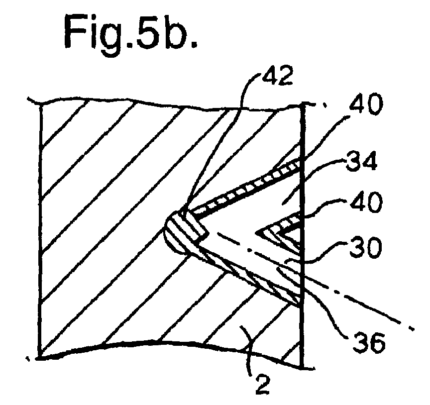
- a first blind hole 34 is laser percussion drilled. Orienting the axis 38 of the laser beam relative to the component 2 controls the orientation of this hole relative to the component 2.
- a second blind hole 36 is drilled.
- the second blind hole is drilled coplanar with the first blind hole 34, oriented such that the holes intersect at a predetermined point 42. Where the blind holes 34,36 intersect one another, the channelling effect, described above, is lost. Hence care must be taken with the orientation of the component relative to the laser to ensure that the required hole is formed.
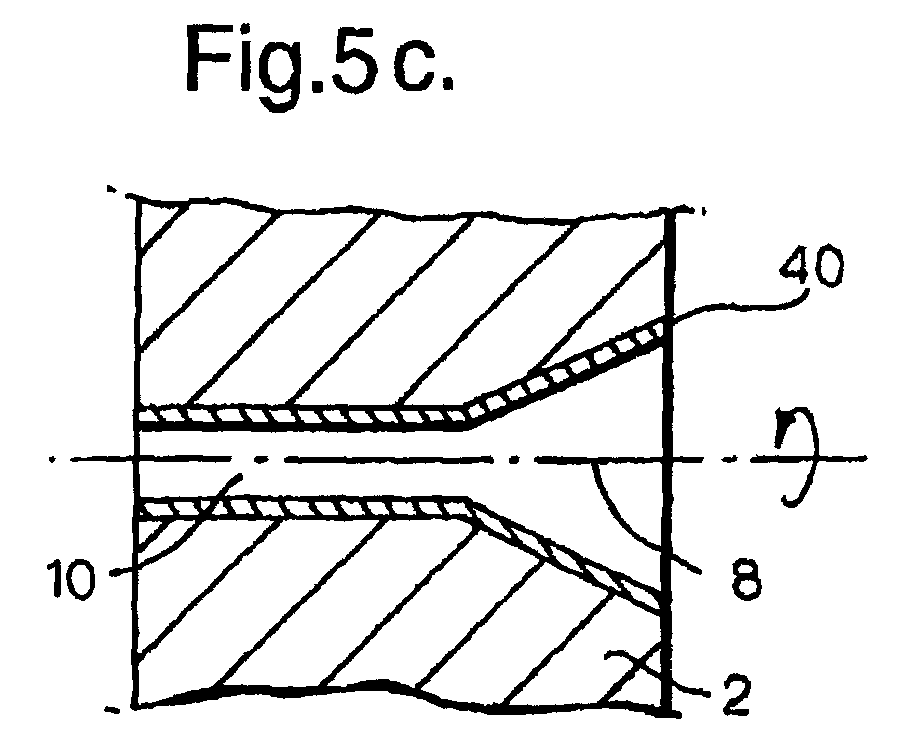
- Figure 6c shows a further step wherein the communicating passage 8 is formed.
- the component 2 is correctly oriented relative to the laser beam and the laser is used to trepan the controlling hole passage.
- a through "pilot" hole is drilled at the centre of the communicating passage.
- the laser beam orbited relative to the component 2, thereby trepanning a hole through the component.
- the diameter of the orbit corresponds to the diameter of the controlling hole 8.
- the laser percussion drilling forms a recast layer 40 about the holes 34,36.
- This recast layer 40 has reduced material properties when compared with the parent metal. It is therefore important to minimise the thickness of the recast layer 40.
- the thickest region of recast 40 are concentrated at the intersection point 42 of the blind holes 34,36 which is subsequently removed when the communication passage 8 is drilled between the fan-shaped cavity 8 and the second surface 9.
- Figure 7a shows a cooling hole 44 produced by conventional EDM and Figure 7b shows a fan shaped hole 46 created according to the present invention.
- the laser drilled cooling hole 46 can be seen to comprise distinctive "flutes" 48 marking the individual blind holes used to form the fan. These have beneficial effects, promoting laminar flow in the airflow exiting the hole.
- the hole forming process described above is a relatively simple cooling hole. It will be understood that this is not limiting. For example where a more complex geometry hole is required a greater number of blind holes would be laser percussion drilled to form the cavity.
- the communicating passage does not need to be laser trepanned. Instead the hole cold be laser percussion drilled, formed via electro discharge machining or drilled by conventional chip machining.
Landscapes
- Engineering & Computer Science (AREA)
- Physics & Mathematics (AREA)
- Optics & Photonics (AREA)
- Mechanical Engineering (AREA)
- Plasma & Fusion (AREA)
- General Engineering & Computer Science (AREA)
- Turbine Rotor Nozzle Sealing (AREA)
- Laser Beam Processing (AREA)
Abstract

Description
- The present invention relates to a method of forming a shaped hole in a component. In particular the present invention relates to the laser drilling of a cooling hole in a component of a gas turbine engine.
- Components in a gas turbine engine are often cooled to survive the high temperatures found therein. One method used is thin film cooling by a supply to air, used as a cooling fluid, is provided to a passage within the component, exiting via cooling holes to form a thin film over the external surface of the component. In addition to removing heat from the component by conduction, the thin film of cooling air serves to prevent hot gas within the gas turbine engine impinging upon the component.
- The cooling air used for thin film cooling must be supplied at a pressure greater than the gas path pressure in which the component is operating. This requires work to be carried out on the cooling air, representing a loss of useful power from the engine. In order to minimise the work required and hence maximise the efficiency of the engine, the cooling holes are shaped to optimise the use of cooling air. The shape most commonly used is a 2D diverging hole exiting at low incidence to the surface of the component to be cooled. This "fan" shaped hole allows the cooling film to form more readily than would a conventional constant-bore hole.
- At present, such cooling holes are manufactured using EDM spark erosion. This places the component and an electrode in a dielectric such as kerosene or de-ionised water. When a voltage is applied across a small gap between the electrode and the component, material is spark eroded from both. By advancing the electrode into the component a hole is formed. Furthermore, by moving the feed axis of the electrode relative to the component, different shapes can be produced.
- However, the EDM process has weaknesses. Electrodes tend to bend or skid when used at very shallow angles to the surface. When combined with other problems, such as arcing or damaged electrodes, the repeatability of the process can be poor leading to high levels of scrap. Other problems include lack of flexibility, due to the need for bespoke tooling for each component configuration and a slow process time.
- Rolls-Royce's European Patent Application No 89310322.6 describes a laser drilling apparatus for drilling shaped holes in a workpiece. However the holes produced by the apparatus are novel in geometry. The present invention provides the ability to laser drill cooling holes that closely approximate "conventional" cooling holes. This is advantageous as the technology can be used to manufacture existing engine components without necessitating redesign.
- According to the present invention there is provided a method of forming a through hole in a component between a first surface and a second surface thereof, the through hole comprising a cavity formed in the first surface and a communicating passage between the cavity and the second surface comprising the steps of:
- laser percussion drilling a plurality of blind holes in the first surface to form the cavity,
then forming the communicating passage between the cavity and the second surface. -
- The invention and apparatus for carrying it out will now be described in more detail with reference to the accompanying drawings in which:
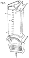
- Figure 1 shows a gas turbine engine component,
- Figure 2 shows a cross-section through the component illustrating the geometry of a cooling hole,
- Figure 3 shows a view on A of Figure 2 illustrating the structure of a cooling,
- Figure 4 (a,b,c) illustrate the conventional laser percussions drilling process for forming a through hole in a component.
- Figure 5 (a,b,c) illustrate the method for forming the cooling hole according to the present invention, and
- Figure 6 (a,b) show a cooling hole produced by EDM and the same cooling hole produced according to the present invention.
-
- Referring now to Figure 1 a
gas turbine component 2 is shown. Thecomponent 2 is a nozzle guide vane used in a gas turbine engine, located in the hot gas path immediately downstream of the engine combustor (not shown). In order to operate in such a hostile environment thecomponent 2 is provided with a number of thin film cooling holes 4.Cooling air 5, provided to an internal passage of the component exits through the cooling holes to form a thin cooling film 6 over an externalfirst surface 7 of the component. - Referring now to Figure 2 a cross section of a film cooling hole 4 is shown to illustrate the general construction of such a feature. The cooling hole 4 comprises a communicating
passage 8 and a fan shapedcavity 10. The communicatingpassage 8, typically of constant bore, provides communication between an internalsecond surface 11, bounding aninternal passage 12 of the component, and the fan shapedcavity 10. Thepassage 8 is also called a controlling hole as it meters the flow of coolingair 5. The fan shapedcavity 10 diverges from apoint 13 located within the bore of the controllingpassage 8 hole until it meets the external surface of thecomponent 2. The fan shapedcavity 10 is so shaped to encourage cooling air emerging from it to fan out, thus forming an effective cooling film 6. - Figure 3 shows a view along the bore of the cooling hole 4 to provide further illustration of the
cavity 10 geometry. The communicatingpassage 8 has a round bore. The fan shapedcavity 10 diverges from this bore such that a lozengeshaped exit aperture 14 is formed where thecavity 10 intersects theexternal surface 7 of thecomponent 2. - At present, cooling holes 4 are manufactured using EDM spark erosion. The present invention proposes the formation of the cooling hole by laser drilling, in particular the use of laser percussion drilling to form the fan shaped
cavity 10. - Referring now to Figure 4 the process of conventional laser percussion drilling is illustrated.
- Conventionally, laser percussion drilling is used to form a through
hole 20 in acomponent 22. First, as shown in Figure 5a, apulsed laser beam 24 is directed at thecomponent 22. As shown in Figure 5b the energy of the beam ablates material from thecomponent 22 such that ahole 26 is formed which becomes progressively deeper with each pulse. Such pulses are typically arranged in a pattern, which is repeated until the throughhole 20 shown in Figure 5c is formed. The duration of the pulses, the pauses between pulses and the pauses between patterns are controlled to ensure the optimum conditions for drilling. - The
diameter 28 of thehole 20 is controlled by defocusing thelaser beam 24 to control the area of thecomponent 22 struck by the coherent radiation of thelaser 24. As the hole forms, thelaser beam 38 is channelled by thehole 20 itself, which prevents thelaser beam 24 from diffusing. This is beneficial as the it allows the same diameter to be maintained throughout the length of the hole without having to alter the position of thefocus 32, however, this channelling effect dissipates energy and percussion drilled holes tend to taper inwards, an effect more pronounced with deeper holes. - Conventionally, laser percussion drilling is used to form through holes. Turning now to Figure 5, the present invention utilises laser percussion drilling to form a number of blind holes, 34,36. By controlling the energy of the laser pulses and controlling the number of pulses delivered the holes are drilled to a predetermined depth.
- First as shown in Figure 5a a first
blind hole 34 is laser percussion drilled. Orienting theaxis 38 of the laser beam relative to thecomponent 2 controls the orientation of this hole relative to thecomponent 2. - In a following step, as shown in Figure 6b a second
blind hole 36 is drilled. The second blind hole is drilled coplanar with the firstblind hole 34, oriented such that the holes intersect at apredetermined point 42. Where theblind holes - Figure 6c shows a further step wherein the communicating
passage 8 is formed. Thecomponent 2 is correctly oriented relative to the laser beam and the laser is used to trepan the controlling hole passage. First, a through "pilot" hole is drilled at the centre of the communicating passage. Then, the laser beam orbited relative to thecomponent 2, thereby trepanning a hole through the component. The diameter of the orbit corresponds to the diameter of thecontrolling hole 8. - Shown in Figures 6a and 6b the laser percussion drilling forms a recast
layer 40 about theholes layer 40 has reduced material properties when compared with the parent metal. It is therefore important to minimise the thickness of the recastlayer 40. By forming the fan shapedcavity 8 from a_number of intersectingblind holes intersection point 42 of theblind holes communication passage 8 is drilled between the fan-shapedcavity 8 and the second surface 9. - For comparison, Figure 7a shows a
cooling hole 44 produced by conventional EDM and Figure 7b shows a fan shapedhole 46 created according to the present invention. Though the holes meet the same design specification, the laser drilledcooling hole 46 can be seen to comprise distinctive "flutes" 48 marking the individual blind holes used to form the fan. These have beneficial effects, promoting laminar flow in the airflow exiting the hole. - The hole forming process described above is a relatively simple cooling hole. It will be understood that this is not limiting. For example where a more complex geometry hole is required a greater number of blind holes would be laser percussion drilled to form the cavity.
- Similarly the communicating passage does not need to be laser trepanned. Instead the hole cold be laser percussion drilled, formed via electro discharge machining or drilled by conventional chip machining.
Claims (9)
- A method of forming a through hole in a component between a first surface and a second surface thereof, the through hole comprising a cavity formed in the first surface and a communicating passage between the cavity and the second surface comprising the steps of:laser percussion drilling a plurality of blind holes in the first surface to form the cavity,then forming the communicating passage between the cavity and the second surface.
- A method of forming a through hole as claimed in claim 1 wherein the plurality of blind holes intersect.
- A method of forming a through hole as claimed in claim 1 or claim 2 wherein the plurality of blind holes are coplanar.
- A method of forming a through hole as claimed in any preceding claim wherein the communicating passage is formed by laser drilling.
- A method of forming a through hole as claimed in any preceding claim wherein the cavity and communicating passage are drilled from a common direction.
- A component having a hole formed according to claim 9 or claim 10 wherein the laser drilled blind holes that form the cavity interact at a point located between the first and second surface of the component.
- A component having a hole formed according to any of claims 9 through 11 wherein the laser drilled blind holes that form the cavity converge at a point located within the communicating passage.
- A component having a hole formed according to any of claims 9 through 12 wherein the laser drilled blind holes that form the cavity are coplanar.
- A component having a hole formed according to any of claims 9 through 13 wherein the cavity is a fan shaped slot, narrowing as it projects into the component.
Applications Claiming Priority (2)
| Application Number | Priority Date | Filing Date | Title |
|---|---|---|---|
| GB0126006 | 2001-10-30 | ||
| GB0126006A GB2381489B (en) | 2001-10-30 | 2001-10-30 | Method of forming a shaped hole |
Publications (2)
| Publication Number | Publication Date |
|---|---|
| EP1308236A1 true EP1308236A1 (en) | 2003-05-07 |
| EP1308236B1 EP1308236B1 (en) | 2010-04-07 |
Family
ID=9924773
Family Applications (1)
| Application Number | Title | Priority Date | Filing Date |
|---|---|---|---|
| EP02257473A Expired - Lifetime EP1308236B1 (en) | 2001-10-30 | 2002-10-28 | Method of forming a shaped hole |
Country Status (4)
| Country | Link |
|---|---|
| US (2) | US6781091B2 (en) |
| EP (1) | EP1308236B1 (en) |
| DE (1) | DE60235863D1 (en) |
| GB (1) | GB2381489B (en) |
Cited By (5)
| Publication number | Priority date | Publication date | Assignee | Title |
|---|---|---|---|---|
| WO2011038788A1 (en) * | 2009-02-27 | 2011-04-07 | Picodrill Sa | A method of generating a hole or recess or well in a substrate, a device for carrying out the method, and a high frequency high voltage source for use in such a device |
| WO2012057908A3 (en) * | 2010-10-29 | 2013-09-12 | General Electric Company | Substrate with shaped cooling holes and methods of manufacture |
| EP2248997A3 (en) * | 2009-05-05 | 2016-02-10 | General Electric Company | System and method for improved film cooling |
| US9696035B2 (en) | 2010-10-29 | 2017-07-04 | General Electric Company | Method of forming a cooling hole by laser drilling |
| US10239157B2 (en) | 2016-04-06 | 2019-03-26 | General Electric Company | Additive machine utilizing rotational build surface |
Families Citing this family (29)
| Publication number | Priority date | Publication date | Assignee | Title |
|---|---|---|---|---|
| GB2395157B (en) * | 2002-11-15 | 2005-09-07 | Rolls Royce Plc | Laser driliing shaped holes |
| US7223072B2 (en) * | 2004-01-27 | 2007-05-29 | Honeywell International, Inc. | Gas turbine engine including airfoils having an improved airfoil film cooling configuration and method therefor |
| US7540083B2 (en) * | 2005-09-28 | 2009-06-02 | Honeywell International Inc. | Method to modify an airfoil internal cooling circuit |
| US20090003987A1 (en) * | 2006-12-21 | 2009-01-01 | Jack Raul Zausner | Airfoil with improved cooling slot arrangement |
| US8007237B2 (en) | 2006-12-29 | 2011-08-30 | Pratt & Whitney Canada Corp. | Cooled airfoil component |
| US7812282B2 (en) * | 2007-03-15 | 2010-10-12 | Honeywell International Inc. | Methods of forming fan-shaped effusion holes in combustors |
| US7820267B2 (en) * | 2007-08-20 | 2010-10-26 | Honeywell International Inc. | Percussion drilled shaped through hole and method of forming |
| US20090169394A1 (en) * | 2007-12-28 | 2009-07-02 | General Electric Company | Method of forming cooling holes and turbine airfoil with hybrid-formed cooling holes |
| US10189100B2 (en) | 2008-07-29 | 2019-01-29 | Pratt & Whitney Canada Corp. | Method for wire electro-discharge machining a part |
| US8925201B2 (en) * | 2009-06-29 | 2015-01-06 | Pratt & Whitney Canada Corp. | Method and apparatus for providing rotor discs |
| EP2286955B1 (en) * | 2009-08-17 | 2012-06-13 | Siemens Aktiengesellschaft | Method for making a hole using different laser positions |
| WO2011020490A1 (en) * | 2009-08-17 | 2011-02-24 | Siemens Aktiengesellschaft | Method for producing an asymmetric diffuser using different laser positions |
| US20110097191A1 (en) * | 2009-10-28 | 2011-04-28 | General Electric Company | Method and structure for cooling airfoil surfaces using asymmetric chevron film holes |
| US9890647B2 (en) * | 2009-12-29 | 2018-02-13 | Rolls-Royce North American Technologies Inc. | Composite gas turbine engine component |
| US8857055B2 (en) * | 2010-01-29 | 2014-10-14 | General Electric Company | Process and system for forming shaped air holes |
| EP2712700A1 (en) * | 2010-05-04 | 2014-04-02 | Siemens Aktiengesellschaft | Laser drills without burr formation |
| US8905713B2 (en) | 2010-05-28 | 2014-12-09 | General Electric Company | Articles which include chevron film cooling holes, and related processes |
| US9157328B2 (en) | 2010-12-24 | 2015-10-13 | Rolls-Royce North American Technologies, Inc. | Cooled gas turbine engine component |
| EP2568118A1 (en) * | 2011-09-12 | 2013-03-13 | Siemens Aktiengesellschaft | Gas-turbine-component |
| US9931712B2 (en) | 2012-01-11 | 2018-04-03 | Pim Snow Leopard Inc. | Laser drilling and trepanning device |
| GB201205020D0 (en) * | 2012-03-22 | 2012-05-09 | Rolls Royce Plc | A method of manufacturing a thermal barrier coated article |
| EP2886798B1 (en) | 2013-12-20 | 2018-10-24 | Rolls-Royce Corporation | mechanically machined film cooling holes |
| US20160090843A1 (en) * | 2014-09-30 | 2016-03-31 | General Electric Company | Turbine components with stepped apertures |
| US9611824B2 (en) * | 2015-02-18 | 2017-04-04 | Caterpillar Inc. | Process for manufacturing an injector body |
| US20190071977A1 (en) * | 2017-09-07 | 2019-03-07 | General Electric Company | Component for a turbine engine with a cooling hole |
| US10760431B2 (en) | 2017-09-07 | 2020-09-01 | General Electric Company | Component for a turbine engine with a cooling hole |
| DE102018113508A1 (en) * | 2018-06-06 | 2019-12-12 | Liebherr-Components Deggendorf Gmbh | Process for making a nozzle |
| US11585224B2 (en) | 2020-08-07 | 2023-02-21 | General Electric Company | Gas turbine engines and methods associated therewith |
| EP4155504A1 (en) * | 2021-09-03 | 2023-03-29 | Raytheon Technologies Corporation | Multi-step method for machining blind opening in ceramic component |
Citations (3)
| Publication number | Priority date | Publication date | Assignee | Title |
|---|---|---|---|---|
| EP0365195A2 (en) * | 1988-10-12 | 1990-04-25 | ROLLS-ROYCE plc | Laser machining method |
| US5511946A (en) * | 1994-12-08 | 1996-04-30 | General Electric Company | Cooled airfoil tip corner |
| US5747769A (en) * | 1995-11-13 | 1998-05-05 | General Electric Company | Method of laser forming a slot |
Family Cites Families (8)
| Publication number | Priority date | Publication date | Assignee | Title |
|---|---|---|---|---|
| US6744010B1 (en) * | 1991-08-22 | 2004-06-01 | United Technologies Corporation | Laser drilled holes for film cooling |
| US5609779A (en) * | 1996-05-15 | 1997-03-11 | General Electric Company | Laser drilling of non-circular apertures |
| US5837964A (en) * | 1998-01-16 | 1998-11-17 | Chromalloy Gas Turbine Corporation | Laser drilling holes in components by combined percussion and trepan drilling |
| EP0950463B1 (en) * | 1998-03-23 | 2002-01-23 | Alstom | Non-circular cooling hole and method of manufacturing the same |
| US6362446B1 (en) * | 1999-08-02 | 2002-03-26 | General Electric Company | Method for drilling hollow components |
| DE19960797C1 (en) * | 1999-12-16 | 2001-09-13 | Mtu Aero Engines Gmbh | Method for producing an opening in a metallic component |
| US6573474B1 (en) * | 2000-10-18 | 2003-06-03 | Chromalloy Gas Turbine Corporation | Process for drilling holes through a thermal barrier coating |
| US6420677B1 (en) * | 2000-12-20 | 2002-07-16 | Chromalloy Gas Turbine Corporation | Laser machining cooling holes in gas turbine components |
-
2001
- 2001-10-30 GB GB0126006A patent/GB2381489B/en not_active Expired - Fee Related
-
2002
- 2002-10-28 DE DE60235863T patent/DE60235863D1/en not_active Expired - Lifetime
- 2002-10-28 EP EP02257473A patent/EP1308236B1/en not_active Expired - Lifetime
- 2002-10-30 US US10/283,146 patent/US6781091B2/en not_active Expired - Lifetime
-
2004
- 2004-06-29 US US10/878,017 patent/US6914214B2/en not_active Expired - Lifetime
Patent Citations (3)
| Publication number | Priority date | Publication date | Assignee | Title |
|---|---|---|---|---|
| EP0365195A2 (en) * | 1988-10-12 | 1990-04-25 | ROLLS-ROYCE plc | Laser machining method |
| US5511946A (en) * | 1994-12-08 | 1996-04-30 | General Electric Company | Cooled airfoil tip corner |
| US5747769A (en) * | 1995-11-13 | 1998-05-05 | General Electric Company | Method of laser forming a slot |
Cited By (7)
| Publication number | Priority date | Publication date | Assignee | Title |
|---|---|---|---|---|
| WO2011038788A1 (en) * | 2009-02-27 | 2011-04-07 | Picodrill Sa | A method of generating a hole or recess or well in a substrate, a device for carrying out the method, and a high frequency high voltage source for use in such a device |
| US8736026B2 (en) | 2009-02-27 | 2014-05-27 | Picodrill Sa | Method of generating a hole or recess or well in a substrate |
| EP2248997A3 (en) * | 2009-05-05 | 2016-02-10 | General Electric Company | System and method for improved film cooling |
| WO2012057908A3 (en) * | 2010-10-29 | 2013-09-12 | General Electric Company | Substrate with shaped cooling holes and methods of manufacture |
| CN103534530A (en) * | 2010-10-29 | 2014-01-22 | 通用电气公司 | Substrate with shaped cooling holes and method of manufacture |
| US9696035B2 (en) | 2010-10-29 | 2017-07-04 | General Electric Company | Method of forming a cooling hole by laser drilling |
| US10239157B2 (en) | 2016-04-06 | 2019-03-26 | General Electric Company | Additive machine utilizing rotational build surface |
Also Published As
| Publication number | Publication date |
|---|---|
| US20030091432A1 (en) | 2003-05-15 |
| US6781091B2 (en) | 2004-08-24 |
| GB2381489B (en) | 2004-11-17 |
| US20040232122A1 (en) | 2004-11-25 |
| GB2381489A (en) | 2003-05-07 |
| EP1308236B1 (en) | 2010-04-07 |
| DE60235863D1 (en) | 2010-05-20 |
| GB2381489A8 (en) | 2003-05-22 |
| GB0126006D0 (en) | 2001-12-19 |
| US6914214B2 (en) | 2005-07-05 |
Similar Documents
| Publication | Publication Date | Title |
|---|---|---|
| US6781091B2 (en) | Method of forming a shaped hole | |
| US20220349319A1 (en) | Manufacturing methods for multi-lobed cooling holes | |
| US6420677B1 (en) | Laser machining cooling holes in gas turbine components | |
| US6744010B1 (en) | Laser drilled holes for film cooling | |
| EP1419847B1 (en) | Laser drilling shaped holes | |
| EP2027963B1 (en) | Composant comprising a percussion drilled shaped through hole providing Coanda effect and method of forming the same using laser percussion driling | |
| Yeo et al. | A technical review of the laser drilling of aerospace materials | |
| US6307175B1 (en) | Method of producing a noncircular cooling bore | |
| US7411150B2 (en) | Method of producing a composite component | |
| EP1353773B1 (en) | Method of and system for laser milling | |
| US6359254B1 (en) | Method for producing shaped hole in a structure | |
| McNally et al. | Laser drilling of cooling holes in aeroengines: state of the art and future challenges | |
| EP0375175B1 (en) | Cooled turbomachinery components | |
| EP0365195A2 (en) | Laser machining method | |
| US20110293423A1 (en) | Articles which include chevron film cooling holes, and related processes | |
| US9776284B2 (en) | System and method for cutting a passage in an airfoil | |
| ES2997232T3 (en) | Method and device for laser processing a workpiece | |
| PL200739B1 (en) | Process for drilling holes in a metallic workpiece having a thermal barrier coating | |
| US9770785B2 (en) | System and method for forming a cooling hole in an airfoil | |
| CN100379515C (en) | Composite element, method for manufacturing same and turbomachine comprising same | |
| Dürr | Laser drilling in industrial use: strategies and applications | |
| EP3053700A1 (en) | System and method for forming passages in an airfoil | |
| CN115815836A (en) | A Method of Millisecond Long Pulse Laser Machining Expansion Hole | |
| Mendiratta et al. | Water‐Assisted Microhole Drilling with Nanosecond Lasers | |
| Corfe et al. | Drilling |
Legal Events
| Date | Code | Title | Description |
|---|---|---|---|
| PUAI | Public reference made under article 153(3) epc to a published international application that has entered the european phase |
Free format text: ORIGINAL CODE: 0009012 |
|
| AK | Designated contracting states |
Designated state(s): AT BE BG CH CY CZ DE DK EE ES FI FR GB GR IE IT LI LU MC NL PT SE SK TR |
|
| AX | Request for extension of the european patent |
Extension state: AL LT LV MK RO SI |
|
| 17P | Request for examination filed |
Effective date: 20030704 |
|
| 17Q | First examination report despatched |
Effective date: 20030902 |
|
| AKX | Designation fees paid |
Designated state(s): DE FR GB |
|
| 17Q | First examination report despatched |
Effective date: 20030902 |
|
| GRAP | Despatch of communication of intention to grant a patent |
Free format text: ORIGINAL CODE: EPIDOSNIGR1 |
|
| GRAS | Grant fee paid |
Free format text: ORIGINAL CODE: EPIDOSNIGR3 |
|
| GRAA | (expected) grant |
Free format text: ORIGINAL CODE: 0009210 |
|
| AK | Designated contracting states |
Kind code of ref document: B1 Designated state(s): DE FR GB |
|
| REG | Reference to a national code |
Ref country code: GB Ref legal event code: FG4D |
|
| REF | Corresponds to: |
Ref document number: 60235863 Country of ref document: DE Date of ref document: 20100520 Kind code of ref document: P |
|
| PLBE | No opposition filed within time limit |
Free format text: ORIGINAL CODE: 0009261 |
|
| STAA | Information on the status of an ep patent application or granted ep patent |
Free format text: STATUS: NO OPPOSITION FILED WITHIN TIME LIMIT |
|
| 26N | No opposition filed |
Effective date: 20110110 |
|
| REG | Reference to a national code |
Ref country code: DE Ref legal event code: R082 Ref document number: 60235863 Country of ref document: DE Representative=s name: FLEUCHAUS & GALLO PARTNERSCHAFT MBB, DE |
|
| REG | Reference to a national code |
Ref country code: FR Ref legal event code: PLFP Year of fee payment: 14 |
|
| REG | Reference to a national code |
Ref country code: FR Ref legal event code: PLFP Year of fee payment: 15 |
|
| REG | Reference to a national code |
Ref country code: FR Ref legal event code: CA Effective date: 20170517 |
|
| REG | Reference to a national code |
Ref country code: FR Ref legal event code: PLFP Year of fee payment: 16 |
|
| REG | Reference to a national code |
Ref country code: FR Ref legal event code: PLFP Year of fee payment: 17 |
|
| PGFP | Annual fee paid to national office [announced via postgrant information from national office to epo] |
Ref country code: DE Payment date: 20181029 Year of fee payment: 17 |
|
| PGFP | Annual fee paid to national office [announced via postgrant information from national office to epo] |
Ref country code: GB Payment date: 20181029 Year of fee payment: 17 Ref country code: FR Payment date: 20181025 Year of fee payment: 17 |
|
| REG | Reference to a national code |
Ref country code: DE Ref legal event code: R119 Ref document number: 60235863 Country of ref document: DE |
|
| PG25 | Lapsed in a contracting state [announced via postgrant information from national office to epo] |
Ref country code: DE Free format text: LAPSE BECAUSE OF NON-PAYMENT OF DUE FEES Effective date: 20200501 |
|
| GBPC | Gb: european patent ceased through non-payment of renewal fee |
Effective date: 20191028 |
|
| PG25 | Lapsed in a contracting state [announced via postgrant information from national office to epo] |
Ref country code: FR Free format text: LAPSE BECAUSE OF NON-PAYMENT OF DUE FEES Effective date: 20191031 Ref country code: GB Free format text: LAPSE BECAUSE OF NON-PAYMENT OF DUE FEES Effective date: 20191028 |