EP1308173A1 - Apparatus and process for concentrating a sterilant and sterilizing articles with the concentrated sterilant - Google Patents
Apparatus and process for concentrating a sterilant and sterilizing articles with the concentrated sterilant Download PDFInfo
- Publication number
- EP1308173A1 EP1308173A1 EP02257623A EP02257623A EP1308173A1 EP 1308173 A1 EP1308173 A1 EP 1308173A1 EP 02257623 A EP02257623 A EP 02257623A EP 02257623 A EP02257623 A EP 02257623A EP 1308173 A1 EP1308173 A1 EP 1308173A1
- Authority
- EP
- European Patent Office
- Prior art keywords
- solution
- chamber
- vaporizer
- hydrogen peroxide
- water
- Prior art date
- Legal status (The legal status is an assumption and is not a legal conclusion. Google has not performed a legal analysis and makes no representation as to the accuracy of the status listed.)
- Granted
Links
Images






Classifications
-
- A—HUMAN NECESSITIES
- A61—MEDICAL OR VETERINARY SCIENCE; HYGIENE
- A61L—METHODS OR APPARATUS FOR STERILISING MATERIALS OR OBJECTS IN GENERAL; DISINFECTION, STERILISATION OR DEODORISATION OF AIR; CHEMICAL ASPECTS OF BANDAGES, DRESSINGS, ABSORBENT PADS OR SURGICAL ARTICLES; MATERIALS FOR BANDAGES, DRESSINGS, ABSORBENT PADS OR SURGICAL ARTICLES
- A61L2/00—Disinfection or sterilisation of materials or objects, in general; Accessories therefor
- A61L2/16—Disinfection or sterilisation of materials or objects, in general; Accessories therefor using chemical substances
- A61L2/20—Gaseous substances, e.g. vapours
- A61L2/208—Hydrogen peroxide
-
- A—HUMAN NECESSITIES
- A61—MEDICAL OR VETERINARY SCIENCE; HYGIENE
- A61L—METHODS OR APPARATUS FOR STERILISING MATERIALS OR OBJECTS IN GENERAL; DISINFECTION, STERILISATION OR DEODORISATION OF AIR; CHEMICAL ASPECTS OF BANDAGES, DRESSINGS, ABSORBENT PADS OR SURGICAL ARTICLES; MATERIALS FOR BANDAGES, DRESSINGS, ABSORBENT PADS OR SURGICAL ARTICLES
- A61L2/00—Disinfection or sterilisation of materials or objects, in general; Accessories therefor
- A61L2/24—Apparatus using programmed or automatic operation
-
- A—HUMAN NECESSITIES
- A61—MEDICAL OR VETERINARY SCIENCE; HYGIENE
- A61B—DIAGNOSIS; SURGERY; IDENTIFICATION
- A61B1/00—Instruments for performing medical examinations of the interior of cavities or tubes of the body by visual or photographical inspection, e.g. endoscopes; Illuminating arrangements therefor
- A61B1/12—Instruments for performing medical examinations of the interior of cavities or tubes of the body by visual or photographical inspection, e.g. endoscopes; Illuminating arrangements therefor with cooling or rinsing arrangements
- A61B1/121—Instruments for performing medical examinations of the interior of cavities or tubes of the body by visual or photographical inspection, e.g. endoscopes; Illuminating arrangements therefor with cooling or rinsing arrangements provided with means for cleaning post-use
-
- A—HUMAN NECESSITIES
- A61—MEDICAL OR VETERINARY SCIENCE; HYGIENE
- A61B—DIAGNOSIS; SURGERY; IDENTIFICATION
- A61B1/00—Instruments for performing medical examinations of the interior of cavities or tubes of the body by visual or photographical inspection, e.g. endoscopes; Illuminating arrangements therefor
- A61B1/12—Instruments for performing medical examinations of the interior of cavities or tubes of the body by visual or photographical inspection, e.g. endoscopes; Illuminating arrangements therefor with cooling or rinsing arrangements
- A61B1/121—Instruments for performing medical examinations of the interior of cavities or tubes of the body by visual or photographical inspection, e.g. endoscopes; Illuminating arrangements therefor with cooling or rinsing arrangements provided with means for cleaning post-use
- A61B1/123—Instruments for performing medical examinations of the interior of cavities or tubes of the body by visual or photographical inspection, e.g. endoscopes; Illuminating arrangements therefor with cooling or rinsing arrangements provided with means for cleaning post-use using washing machines
-
- A—HUMAN NECESSITIES
- A61—MEDICAL OR VETERINARY SCIENCE; HYGIENE
- A61L—METHODS OR APPARATUS FOR STERILISING MATERIALS OR OBJECTS IN GENERAL; DISINFECTION, STERILISATION OR DEODORISATION OF AIR; CHEMICAL ASPECTS OF BANDAGES, DRESSINGS, ABSORBENT PADS OR SURGICAL ARTICLES; MATERIALS FOR BANDAGES, DRESSINGS, ABSORBENT PADS OR SURGICAL ARTICLES
- A61L2/00—Disinfection or sterilisation of materials or objects, in general; Accessories therefor
- A61L2/16—Disinfection or sterilisation of materials or objects, in general; Accessories therefor using chemical substances
- A61L2/18—Liquid substances
- A61L2/186—Peroxide solutions
-
- A—HUMAN NECESSITIES
- A61—MEDICAL OR VETERINARY SCIENCE; HYGIENE
- A61L—METHODS OR APPARATUS FOR STERILISING MATERIALS OR OBJECTS IN GENERAL; DISINFECTION, STERILISATION OR DEODORISATION OF AIR; CHEMICAL ASPECTS OF BANDAGES, DRESSINGS, ABSORBENT PADS OR SURGICAL ARTICLES; MATERIALS FOR BANDAGES, DRESSINGS, ABSORBENT PADS OR SURGICAL ARTICLES
- A61L2/00—Disinfection or sterilisation of materials or objects, in general; Accessories therefor
- A61L2/26—Accessories
-
- A—HUMAN NECESSITIES
- A61—MEDICAL OR VETERINARY SCIENCE; HYGIENE
- A61B—DIAGNOSIS; SURGERY; IDENTIFICATION
- A61B90/00—Instruments, implements or accessories specially adapted for surgery or diagnosis and not covered by any of the groups A61B1/00 - A61B50/00, e.g. for luxation treatment or for protecting wound edges
- A61B90/70—Cleaning devices specially adapted for surgical instruments
- A61B2090/701—Cleaning devices specially adapted for surgical instruments for flexible tubular instruments, e.g. endoscopes
-
- A—HUMAN NECESSITIES
- A61—MEDICAL OR VETERINARY SCIENCE; HYGIENE
- A61L—METHODS OR APPARATUS FOR STERILISING MATERIALS OR OBJECTS IN GENERAL; DISINFECTION, STERILISATION OR DEODORISATION OF AIR; CHEMICAL ASPECTS OF BANDAGES, DRESSINGS, ABSORBENT PADS OR SURGICAL ARTICLES; MATERIALS FOR BANDAGES, DRESSINGS, ABSORBENT PADS OR SURGICAL ARTICLES
- A61L2103/00—Materials or objects being the target of disinfection or sterilisation
- A61L2103/15—Laboratory, medical or dentistry appliances, e.g. catheters or sharps
-
- A—HUMAN NECESSITIES
- A61—MEDICAL OR VETERINARY SCIENCE; HYGIENE
- A61L—METHODS OR APPARATUS FOR STERILISING MATERIALS OR OBJECTS IN GENERAL; DISINFECTION, STERILISATION OR DEODORISATION OF AIR; CHEMICAL ASPECTS OF BANDAGES, DRESSINGS, ABSORBENT PADS OR SURGICAL ARTICLES; MATERIALS FOR BANDAGES, DRESSINGS, ABSORBENT PADS OR SURGICAL ARTICLES
- A61L2202/00—Aspects relating to methods or apparatus for disinfecting or sterilising materials or objects
- A61L2202/10—Apparatus features
- A61L2202/12—Apparatus for isolating biocidal substances from the environment
- A61L2202/122—Chambers for sterilisation
Definitions
- the present invention relates to a process and an apparatus for sterilization of medical instruments using a chemical sterilant. More particularly, the invention relates to a process and an apparatus in which sterilization is achieved by concentrating a sterilant such as hydrogen peroxide and sterilizing articles therewith.
- Medical instruments have traditionally been sterilized using either heat, such as is provided by steam, or a chemical, such as formaldehyde or ethylene oxide in the gas or vapor state. Each of these methods has its drawbacks. Many medical devices such as fiberoptic devices, endoscopes, power tools, etc., are sensitive to heat, moisture or both. Formaldehyde and ethylene oxide are both toxic gases that pose a potential hazard to healthcare workers. Problems with ethylene oxide are particularly severe, because its use requires long aeration times to remove the gas from articles that have been sterilized. This lengthens the sterilization cycle time undesirably.
- pre-measured amounts of a hydrogen peroxide and water solution are provided in sealed enclosure, such as a capsule inside of a cassette housing which can be automatically opened by the system to reduce contact between the system user and the hydrogen peroxide solution.
- sealed enclosure such as a capsule inside of a cassette housing which can be automatically opened by the system to reduce contact between the system user and the hydrogen peroxide solution.
- the pump that is evacuating the prechamber draws out the water vapor thus released from solution to concentrate the remaining solution.
- Cummings carries out the concentration process in the prechamber which is physically isolated from the main chamber. This adds complexity by requiring additional chambers, pumps and valves.
- U.S. Patent No. 4,952,370 issued August 28, 1990 and entitled “Hydrogen Peroxide Sterilization Method” discloses a sterilization process in which aqueous hydrogen peroxide vapor is first condensed on the article to be sterilized, followed by application of a vacuum to the sterilization chamber to remove the water and hydrogen peroxide from the article.
- This method is suitable for surface sterilization, but not for sterilization of diffusion-restricted areas such as long narrow lumens because it depends on the diffusion of hydrogen peroxide vapor into the lumen to effect sterilization.
- U.S. Patent No. 4,943,414 issued July 24, 1990 and entitled "Method for Vapor Sterilization of Articles Having Lumens” discloses a process in which a vessel containing a small amount of a vaporizable liquid sterilant solution is attached to a lumen, and the sterilant vaporizes and flows directly into the lumen of the article as the pressure is reduced during the sterilization cycle.
- This system has the advantage that the water and hydrogen peroxide vapor are pulled through the lumen by the existing pressure differential, increasing the sterilization rate for lumens, but has the disadvantage that the vessel needs to be attached to each lumen to be sterilized.
- U.S. Patent No. 5,492,672 issued February 20, 1996 and entitled, "Sterilization Apparatus and Method for Multicomponent Sterilant” discloses a process for sterilizing narrow lumens. This process uses a multi-component sterilant vapor and requires successive alternating periods of flow of sterilant vapor and discontinuance of such flow. A complex apparatus is used to accomplish the method. Because flow through of vapor is used, closed end lumens are not readily sterilized in the process.
- a method of sterilizing an article comprises the steps of: placing the article into a chamber containing an inner atmosphere at; introducing a solution comprising hydrogen peroxide and water into a vaporizer in fluid communication with the chamber through a port, the solution having a ratio of hydrogen peroxide to water; pumping a portion of the inner atmosphere out of the chamber through the port thereby reducing pressure in the chamber and in the vaporizer; vaporizing water vapor out of the solution; drawing the water vapor from the vaporizer to increase the ratio of hydrogen peroxide to water in the vaporizer; terminating the pumping step without terminating the vaporizing steps; vaporizing hydrogen peroxide vapor out of the solution and flowing the hydrogen peroxide vapor from the vaporizer into the chamber; and contacting the article with the hydrogen peroxide vapor for a time period sufficient to effect sterilization of the article.
- the ratio of hydrogen peroxide to water in said solution, by weight, after the step of drawing water vapor from the vaporizer exceeds 3 to 1, and more preferably exceeds 4 to 1.
- the ratio of hydrogen peroxide to water in solution prior to drawing the water is preferably less than 3 to 2.
- the step of drawing water vapor from the vaporizer preferably comprises introducing said solution within a diffusion restricted environment in fluid communication with the chamber during the step of vaporizing the solution.
- the diffusion restricted environment is preferably more diffusion restricted during the step of drawing water vapor from the vaporizer than during a portion of the step of flowing the hydrogen peroxide vapor from the vaporizer into the chamber.
- At least a portion of the pumping step and the vaporizing step can occur simultaneously, and at least a portion of the pumping step, the vaporizing step and the drawing step can occur simultaneously.
- the step of drawing water vapor from the vaporizer comprises the step of maintaining the solution at a pressure below the vapor pressure of the water in the solution and above the vapor pressure of the hydrogen peroxide in the solution.
- the temperature of the solution during the vaporizing step can be held below the temperature of the atmosphere in the chamber whereby to increase the vapor pressure of the water in the solution relative to the hydrogen peroxide in the solution whereby to enhance vaporization of the water from the solution in preference to vaporizing the hydrogen peroxide from the solution.
- the temperature of the atmosphere in the chamber can be above room temperature with the temperature of the solution during the vaporizing step at least 10° C below the temperature of the atmosphere in the chamber.
- the vaporizer can be thermally isolated from the chamber.
- the solution can be vaporized by pumping a portion of the atmosphere out of the vaporizer to lower the pressure at a rate selected to control removal of the water and hydrogen peroxide from the solution so as to concentrate the hydrogen peroxide remaining in the vaporizer.
- One can control the temperature and pressure of the solution during a least a first portion of the vaporizing step so as to vaporize water from the solution and concentrate hydrogen peroxide therein to form a concentrated solution and then raise the temperature of and vaporized this concentrated solution.
- the step of contacting the article with the hydrogen peroxide vapor can be limited to less than one hour and if the article were to have a straight round lumen having two open ends, a diameter of 1mm and a length of 250mm with 10 6 viable spores of B. Stearothermophilus located within the lumen at a midpoint thereof, all of the spores would be killed.
- Air can be bled into said port from exterior of the chamber, preferably from a location between the vaporizer and the chamber.
- the step of terminating the pumping step can comprise closing fluid communication between the pump and the port, as with a valve.
- the vaporizer is preferably located between the chamber and the pump.
- An apparatus is adapted for sterilizing an article with a concentrated hydrogen peroxide vapor.
- the apparatus comprises a source of liquid germicide comprising hydrogen peroxide; a chamber adapted to receive the article, wherein said chamber has a port; a vaporizer in fluid communication with the chamber through the port; and a pump in fluid communication with the chamber through the port.
- a valve is provided to isolate the pump from the chamber and the vaporizer.
- An inlet can be provided to bleed air into the apparatus. It is preferably located either in the chamber or between the vaporizer and the chamber. Preferably, the inlet comprises a valve.
- a second vaporizer can be provided in fluid communication with the chamber through the port.
- a valve can be provided between the first vaporizer and the second vaporizer, to isolate the second vaporizer from the first vaporizer.
- an inlet can be located between the first vaporizer and the second vaporizer, to bleed air into the apparatus.
- FIG. 1 is a schematic diagram of a chamber and accessories suitable for use in the hydrogen peroxide sterilization process of the invention.
- FIG. 2 is a schematic diagram of a chamber, pump and throttle valve for use in the hydrogen peroxide sterilization process of the invention.
- FIG. 3 is a schematic diagram of a system with one pump and two valves, one valve having a larger pump vacuum line for quicker pumpdown and one having a smaller vacuum line for slower pumpdown.
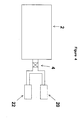
- FIG. 4 is a schematic diagram of a single valve sterilization system having two pumps, one for slower pumpdown and one for quicker pumpdown.
- FIG. 5 is a schematic diagram of a system with two pumps and two valves, one pump for slower pumpdown and one for quicker pumpdown.
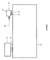
- FIG. 6 is a schematic diagram of a system with a vaporizer.
- FIG. 7 is a schematic diagram of a system with an alternative vaporizer.
- FIG. 8 is a schematic diagram of a system with a further alternative vaporizer.
- FIG. 9 is a graph showing the pressure and vapor peroxide concentration during a concentrating process.
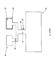
- FIG. 10 is a schematic diagram of a system with a vaporizer and a pump connected to the sterilizer through the same port.
- FIG. 11 is a schematic diagram of a system with more than one vaporizer and a pump connected to the sterilizer through the same port.
- FIGS. 1 and 2 An apparatus useful in the process of the present invention is shown schematically in FIGS. 1 and 2 and comprises a chamber 2, a throttle valve 4 and a pump 6.
- the chamber 2 is attached to the pump 6 by the throttle valve 4.
- the valve 4 can be controlled either automatically or manually to control the pressure.
- the throttle valve 4 opens based on the pressure in the chamber via a pressure transducer and valve controller.
- Such valves are commercially available from, for example, MKS (Andover, MD).
- Hydrogen peroxide can be introduced into the system in any fashion.
- a dilute, aqueous solution of hydrogen peroxide is placed in wells 8 as shown in FIG. 1.
- the aqueous solution of hydrogen peroxide can also be placed within the lumen of long narrow objects to be sterilized.
- the hydrogen peroxide vaporizes and contacts the surface to be sterilized (i.e., colonoscope 10 in FIG. 1) which is placed on metal grid 12 which rests on tray 14.
- the tray can be configured with a plurality of wells designed to retain a known volume of liquid sterilant.
- the volume of sterilization chamber 2 is about 18.5 liters and its dimensions are about 22" (55.9 cm) x 4.25" (10.8 cm) x 12" (30.5 cm).
- FIG. 3 illustrates a parallel two-valve arrangement for use in the sterilization process of the invention.
- the chamber 2 is in fluid communication with the pump 6 via valves 16 and 18.
- Valve 16 mediates the initial rapid evacuation, the first step of a two step evacuation process.
- Valve 18 mediates slow evacuation, the second step of the process, which ensures maximal contact of the article to be sterilized with the vaporized aqueous hydrogen peroxide.
- the pumpdown rate can be controlled by the pumping speed and/or the percent opening of the valve. Either valve can be used to control the pressure.
- the number of its molecules in the vapor state greatly increases thus raising the pressure in the system and requiring additional pumping to extract the water vapor and other molecules to control the pressure. Also, the vapor pressures change with changing conditions within the chamber.
- FIG. 4 illustrates a sterilization apparatus having two pumps 20 and 22, and one valve 4. Pump 20 allows quicker pumpdown of the chamber 2, while pump 22 allows slower pumpdown.
- FIG. 5 illustrates an alternate configuration having two valves 24 and 26 in fluid communication with the pumps 20 and 22, respectively.
- hydrogen peroxide can be introduced into the chamber as a liquid.
- hydrogen peroxide is introduced as a vapor and the chamber parameters are changed so that the vapor condenses as a liquid on the surface of interior of an article to be sterilized.
- Such changes include increasing the partial pressure of hydrogen peroxide and/or decreasing the temperature.
- the aqueous solutions of hydrogen peroxide can be relatively dilute, e.g. as low as 1-6% peroxide by weight, since sterilization is not achieved through contact with the hydrogen peroxide solution, but rather is achieved at low temperatures (preferably 15°-80°C, more preferably 20°-60°C, still more preferably 40°-55°C) and in short periods of time (preferably less than one hour, and more preferably less than one-half hour) upon exposure to hydrogen peroxide under vacuum.
- the method of the present invention is particularly effective with articles having diffusion-restricted areas. Such articles include long, narrow lumens, hinges and other articles having spaces where diffusion of vapors is restricted.
- liquid sterilants which have vapor pressures lower than the vapor pressure of the solvent in which they are provided are also contemplated.
- sterilants include, for example, aqueous peracetic acid solution and aqueous glutaraldehyde solution.
- the article to be sterilized is contacted with liquid sterilant prior to the vaporization step to localize at least some of the vaporization in the diffusion-restricted areas.
- Such contacting can be accomplished either directly or indirectly.
- Direct contacting includes methods such as static soaking, flow through, or aerosol spray, or condensation of a vapor. Any other methods involving physically contacting the articles to be sterilized with sterilant would be considered direct contacting.
- Indirect contacting includes those methods in which sterilant is introduced into the chamber, but not directly on or in the articles to be sterilized.
- deep vacuum can be used to remove residual sterilant.
- a plasma can also be used to both enhance sterilization efficacy and to remove residual sterilant.
- the pumps shown schematically in the figures can be any commercially available vacuum pump.
- the Leybold pump can reach a pressure of less than 0.1 torr and the KNF pump can reach a pressure of less than 10 torr.
- excess hydrogen peroxide in the system may leave a residual which is difficult to be removed.
- the vapor concentration of hydrogen peroxide is preferably kept below 30 mg/l, more preferably less than 20 mg/l, and more preferably still less than 15 mg/l. If higher vapor concentrations of hydrogen peroxide are desired, excess residual can be removed using gas plasma.
- substrates such as stainless steel, polyethylene or polypropylene, which do not retain a residual, substantially more peroxide can be present in the vapor phase in the system during sterilization.
- the chamber 2 and the load within the chamber may be dried prior to the introduction of hydrogen peroxide.
- Many means may be employed to drive water out of the chamber. Primarily, this is accomplished by vaporizing the water and pumping it out of the chamber. The vaporization can be accomplished with heat, plasma induction, vacuum or the like, either alone or in combination. Merely drawing a vacuum prior to introducing the hydrogen peroxide accomplishes a beneficial drying of the chamber 2. If the chamber 2 is heated during this process and if a high energy electromagnetic field is applied to urge the water into the plasma phase the drying is enhanced.
- U.S. Patent No. 5,656,238 issued on August 12, 1997 to Spencer at al. and incorporated herein by reference teaches such techniques in more detail.
- FIGS. 6 to 8 show several new preferred methods.
- a chamber 30 is evacuated by a pump 32 separated from the chamber 30 by a throttle valve 34.
- a vaporizer 36 comprises a housing 38 in fluid communication with the chamber 30 and into which extends a liquid feeding nozzle 40 from outside of the chamber 30.
- a cup 42 within the housing 38 receives hydrogen peroxide from the nozzle 40.
- the hydrogen peroxide can be vaporized as it exits the nozzle 40, or more preferably in a controlled fashion from the cup 42 by controlling the temperature of the cup 42 and the pressure in the chamber 30.
- Temperature control of the cup 42 can be as simple as thermally isolating it from the chamber 30, or a more active control system can be employed such a cooling coil or the like to maintain the cup 42 at a desired low temperature.
- the entire vaporizer 36 is thermally isolated from the chamber 30 or temperature controlled in some fashion. Lower temperatures of vaporization enhance the preferential vaporization of water by exploiting the larger difference between the vapor pressures of water and hydrogen peroxide at lower temperatures.
- Creating a diffusion restriction 44 between the vaporizer 36 and chamber 30 enhances the preferential extraction of water vapor from the chamber as water vapor will more easily traverse the diffusion restriction and be pumped out of the chamber during the vaporization process.
- the diffusion restriction 44 may be simply reducing the clearance between the cup 42 and housing 38 through with the vapor must travel to reach the chamber 30.
- FIG. 7 shows a similar chamber 50, pump 52 and valve 54 with modified vaporizer 56.
- the vaporizer 56 comprises a chamber 58 separated from the chamber 50 by a diffusion restriction 60, such as a permeable membrane. Liquid hydrogen peroxide solution enters the chamber 58 through a valve 62.
- FIG. 8 illustrates a similar arrangement with a chamber 70, pump 72, valve 74, and vaporizer 76 with a chamber 78 and valved hydrogen peroxide solution inlet 80. Restriction of the diffusion between the vaporizer chamber 78 and main chamber 70 is variable. During initial vaporization when primarily water is vaporizing the vapors pass through a tight diffusion restriction 82. After the concentration of the hydrogen peroxide solution reaches a given level valve 84 may be opened to speed the vaporization and diffusion of the concentrated hydrogen peroxide solution.
- the temperature in the chamber is no less than 5°C nor more than 150° C, with the range of 40 to 60°C being preferred, and the pressure should be no less than 0.01 torr, nor typically greater than atmosphere during the process, with the lowest vacuum being typically 0.1 torr and the diffusion pressure preferably being between 1 and 15 torr, although other conditions within the spirit of the invention will be apparent to those of skill in the art.
- the vaporizer pressure does not fall below 0.3 torr. Shorter overall cycles are preferred for convenience, with 5 minutes being a desirable goal, but longer times upwards of 6 hours or more may be warranted in some circumstances.
- Tables 1 and 2 illustrate the effectiveness of the present invention with the apparatus as shown in FIG 6.
- the experiments were run on a chamber of 73 liters at 45°C with 1480 mg of 59% hydrogen peroxide solution by weight.
- the vaporizer is separated from the chamber by twelve 2 mm diameter holes to effect diffusion restriction.
- Test A was conducted by opening the valve, evacuating the chamber to 0.3 torr, closing the valve, injecting the peroxide solution into the vaporizer, allowing the water and peroxide to vaporize and diffuse, and venting the chamber.
- Test B was conducted by injecting peroxide solution into the vaporizer at the atmospheric pressure, opening the valve, evacuating the chamber to 2 torr, closing the valve, allowing the remaining water and peroxide to vaporize and diffuse, and venting the chamber.
- Test C was conducted by opening the valve, evacuating the chamber, injecting the peroxide solution into the vaporizer when the chamber was evacuated to 30 torr, continuing to evacuate the chamber to 2 torr, closing the valve, allowing the remaining water and peroxide to vaporize and diffuse, and venting the chamber.
- the procedure for test D was same as test C except the peroxide solution was introduced into the vaporizer at 0.3 torr.
- Test E was conducted by opening the valve, evacuating the chamber to 0.3 torr, closing the valve, injecting the peroxide solution into the vaporizer, allowing the water and peroxide to vaporize and diffuse for 30 seconds, opening the valve, evacuating the chamber to 2 torr, closing the valve, allowing the remaining water and peroxide to vaporize and diffuse, and venting the chamber.
- the tests were conducted by placing one stainless steel wire inoculated with 4.3x10 6 Bacillus stearothermophilus spores at the center of the stainless steel lumen. Four 1 mm lumens with length ranging from 250 mm to 400 mm were used for each test. All the experiments were conducted by controlling the time between the injecting of peroxide solution and the venting of the chamber to 6 minutes. The results indicate that the new concentrating process is more efficacious than the normal process which does not concentrate the peroxide in the chamber. These results also indicate that the peroxide solution can be introduced before evacuating the chamber, during evacuating the chamber with pressure above or below the vapor pressure of peroxide, or after evacuating the chamber with the valve at the either open or closed position.
- an automated control system receives signals of the temperature, pressure and perhaps also the hydrogen peroxide concentration and calculates the optimal pressure at which to maintain the chamber to remove the water from the hydrogen peroxide solution and from the chamber 30. It can also determine when the solution is sufficiently concentrated. For instance, it may be desired to only concentrate the solution to a certain degree so as to minimize the loss of hydrogen peroxide from the chamber, thereby minimizing hydrogen peroxide emissions from the chamber. While preferentially vaporizing the water from the solution, some hydrogen peroxide will also vaporize.
- the valve 34 can be controlled to remove the vapor until the desired ratio is achieved.
- Table 3 compares a sterilization process in which the concentration of hydrogen peroxide is not increased with a process in which it is increased according to the present invention.
- the concentrations of water and peroxide for the normal process without concentrating the peroxide were calculated based on 1480 mg of 59% peroxide solution by weight in a 73 liters chamber.
- Test E procedure described in Table 1 with the same amount of peroxide solution was used to determine the concentrations of water and peroxide in the chamber with the concentrating process.
- the concentration of peroxide was measured with a peroxide monitor and the concentration of water was calculated from the pressure and peroxide monitor readings.
- the concentrating process has less available peroxide in the chamber, but it removes more water than peroxide from the chamber and results in more concentrated peroxide for achieving better efficacy.
- Table 4 also illustrates effects of the ratio of hydrogen peroxide vapor to water vapor in the chamber 30 on the ability to sterilize long narrow lumens or other diffusion restricted environments with Bacillus subtilis var. niger spores on stainless steel blades in 3mm x 500 mm stainless steel lumen.
- Water vapor was first introduced into the system and then essentially pure hydrogen peroxide vapor was introduced by liberation from a solid form.
- the lower concentrations of water show no failures, whereas with the higher ratio in the last column the efficacy decreased and in one test 3 out of 3 samples failed. Therefore, it is desirable to control the amount of water and peroxide in the chamber to achieve better efficacy.
- Table 6 discloses another approach to control this concentrating process by directly monitoring the ratio of peroxide to water in the chamber. The valve is then closed when the desired ratio of peroxide to water is reached.
- the test conditions described in Table 5 were repeated with 1780 mg of 59% peroxide solution by weight. Efficacy tests were also conducted under the same conditions with stainless steel wire inoculated with 4.3x10 6 Bacillus stearothermophilus spores located at the center of the stainless steel lumen.
- Table 7 shows the efficacy of the concentrating process with 12% peroxide solution by weight. Tests were conducted by placing one stainless steel wire inoculated with 2.1x10 6 Bacillus stearothermophilus spores at the center of the stainless steel lumen. Four 1 mm lumens with length ranging from 250 mm to 400 mm were used for each test.
- the normal process was conducted by evacuating the chamber to 0.3 torr, closing the valve, injecting 7400 mg of 12% peroxide solution by weight into the vaporizer, allowing the water and peroxide to vaporize and diffuse for a total of 23 minutes, and venting the chamber.
- the concentrating process was conducted by evacuating the chamber to 0.3 torr, introducing 7400 mg of 12% peroxide solution by weight into the vaporizer with the valve at the open position, allowing the water and peroxide to vaporize and diffuse, closing the valve when the peroxide concentration increased to 0.45 mg/L, allowing the remaining water and peroxide to vaporize and diffuse, and venting the chamber.
- the vaporizer has its own heater and is in communication with the chamber and separated from the chamber with the o-rings. Initially, the heater on the vaporizer was off and the vaporizer was heated to about 45°C due to the heated chamber and air around the vaporizer. As indicated from the pressure and peroxide concentration curves, the majority of molecules vaporized and diffused into the chamber during the first 15 minutes were water. Not much peroxide was vaporized and diffused into the chamber. This is consistent with the data published by Schumb et al., as shown in Table 9, that the concentration of hydrogen peroxide in the vapor phase over a 12% peroxide solution by weight, or 6.7% by mole, is less than 0.5% by mole under our test conditions.
- the vaporizer temperature decreased more than 10°C.
- the valve With the valve at the open position while water and peroxide vaporized and diffused into the chamber, more water is removed from the system than the peroxide, and the peroxide concentration left in the vaporizer is increased.
- the hydrogen peroxide concentration started to increase after 15 minutes. This indicated that the peroxide solution left in the vaporizer had been concentrated by removing enough water from the vaporizer.
- the valve was then closed to retain the remaining peroxide vaporized into the sterilizer.
- the temperature of the vaporizer can then be optionally increased to enhance the vaporization of the remaining peroxide solution left in the vaporizer.
- the concentrating process can also be conducted by connecting the vaporizer and a vacuum pump to the chamber through a common port.
- both a vaporizer 92 and a pump 94 are in fluid communication with a chamber 90 through a common port 91.
- This configuration provides the advantage over FIG. 6 of removing the water vapor during the concentrating process directly to the pump 94 without passing it through the chamber 90.
- the efficacy of peroxide can be enhanced.
- the extraction of air from the chamber 90 during the vaporizing process prevents the released vapors from entering the chamber and thereby obviates the need for a valve or other barrier between the vaporizer 92 and the chamber 90.
- An optional temperature controller 93 controls the rate of vaporization and an optional valve 96 separates the pump 94 from the vaporizer 92 and chamber 90. Evacuation of the chamber 90 and the vaporizer 92 can be controlled by operation of the valve 96 or by turning the pump 94 on or off.
- Another optional valve 98 on the port 91 can flow or bleed air into the system to create a flow from port 91 to the pump 94. This flow hinders flow of water and peroxide from the vaporizer 92 into the chamber 90 during the concentrating process.
- an optional pinhole 99 can be used to bleed air or gas into the system for the same purpose.
- the valve 98 or pinhole 99 can also be located on the chamber 90.
- the pump 94 After sufficiently concentrating the hydrogen peroxide solution in the vaporizer the pump 94 is turned off or isolated from the chamber by closing the valve 96. The low pressure in the vaporizer vaporizes the remaining concentrated peroxide solution which then diffuses into the chamber 90 through port 91. Methods to perform the concentrating process described in Table 1 can be applied to this apparatus to concentrate the peroxide solution. Various vaporizers, such as the vaporizer 56 of FIG. 7 or the vaporizer 76 of FIG. 8, can also be used with this apparatus to enhance the efficiency of the concentrating process.
- the sterilizer comprises valves 96 and 98. The process parameters, temperature and pressure monitoring and controlling apparatuses and methods previously described can also be applied to this configuration.
- the chamber can be evacuated to remove the moisture or water within the chamber or on the load before the concentrating process.
- the drying process may further comprise the use of gas plasma or other heat.
- the liquid hydrogen peroxide solution is first introduced into the vaporizer 92.
- the liquid can be introduced with a cassette delivery system, a bulk delivery system, a syringe, or disposable cell packs or other methods appreciated by those of skill in the art.
- the pump is then turned on to evacuate the system. This creates two directional flows.
- the air in the chamber 90 flows from the chamber 90 to the pump 94, and water vapor and peroxide vapor flow from the vaporizer 92 to the pump 94.
- the flow of air from the chamber 90 to the pump 94 prevents or minimizes the flow of water vapor and peroxide vapor from the vaporizer 92 to the chamber 90.
- the concentrating efficiency of the hydrogen peroxide solution in the vaporizer 92 can be controlled by controlling the pumping rate, the pressure, and/or the vaporizer temperature.
- the valve 98 and/or a pinhole 99 can be used to further reduce or eliminate the flow of water vapor and peroxide vapor from the vaporizer 92 into the chamber 90.
- the pump 94 is then turned off or the valve 96 is then closed to allow vaporization of the remaining concentrated peroxide and water from the vaporizer 92 through the port 91 and into the chamber 90.
- a temperature controller 93 located outside of the vaporizer 92 can be set at various temperatures throughout the cycle to optimize the concentrating process and the vaporization of the concentrated peroxide.
- FIG. 11 illustrates an apparatus as in FIG. 10, but with two vaporizers 101 and 102 in fluid communication with a chamber 100 through the port 104.
- the second vaporizer provides additional dose of peroxide to the chamber.
- the peroxide solution or the source of peroxide solution can be introduced into the vaporizers at the same time or separately as needed.
- the vaporizer temperatures can be set differently to independently control the vaporization of the water and peroxide from each vaporizer.
- a valve 105 can be used to isolate the pump 103.
- Optional valves 106 and 108 and pinholes 109 and 110 can be used to control the direction of the flow of water vapor and peroxide vapor during the concentrating process and/or during the vaporization of the concentrated peroxide solution from the vaporizers 101 and 102 into the chamber 100.
- a valve 107 can be used to separate the vaporizer 102 from the vaporizer 101.
- a sterilizer can be designed to have more than two vaporizers.
- the length of the concentrating process or the time to close the valve can control the final peroxide concentration or the ratio of the peroxide to the water in the chamber. Since water has a higher vapor pressure than peroxide at the same temperature, the concentration of peroxide in the vaporizer or the chamber can be increased by increasing the time of the concentrating process or by delaying the time to close the valve.
- This concentrating process can be conducted. with peroxide solution in the chamber and/or in the vaporizer which is in fluid communication with the chamber, and it can be enhanced if the environment, which contains the peroxide solution, is a diffusion-restricted area. Monitoring or determining the concentration of water and/or peroxide in the chamber and/or vaporizer can properly control this concentrating process.
- the concentration of peroxide is an important factor to achieve good efficacy for the vapor phase peroxide process. Based on the test results of this invention, it is believed that the ratio of peroxide to water is a critical factor in the sterilization process. By determining the concentrations of peroxide and water in the process and calculating the ratio of peroxide to water, parametric release can be achieved. By determining the vapor composition and monitoring the temperature of the peroxide solution, the concentration of the peroxide solution can be determined. Vapor composition (mole fraction H2O2) over hydrogen peroxide water solutions Temp.
- Table 10A has the ratios of hydrogen peroxide to water in the vapor phase with 10%, 20% and 30% hydrogen peroxide solutions by mole under various temperatures. Ratio of peroxide to water in the vapor phase over hydrogen peroxide solutions 10% by mole or 17.3% by weight in solution 20% by mole or 32.1% by weight in solution 30% by mole or 44.7% by weight in solution Temp.
- Ratio of peroxide to water in the vapor phase over hydrogen peroxide solutions 40% by mole or 55.7% by weight in solution 50% by mole or 65.4% by weight in solution 60% by mole or 73.9% by weight in solution Temp. (°C)
- Ratio of peroxide to water in vapor by mole Ratio of peroxide to water in vapor by weight
- Ratio of peroxide to water in vapor by mole Ratio of peroxide to water in vapor by mole
- Ratio of peroxide to water in vapor by mole Ratio of peroxide to water in vapor by weight
- Ratio of peroxide to water in vapor by weight 0 0.0320 0.0604 0.0638 0.1206 0.1261 0.2382 10 0.0384 0.0726 0.0753 0.1422 0.1468 0.2773
- 0.0428 0.0808 0.0834 0.1576 0.1601 0.3024
- 0.0460 0.0869 0.0881 0.1665 0.1682 0.3178 30
- the process may be further enhanced by admitting sufficient hydrogen peroxide into the system so as to force some of the vaporized solution to condense upon the instruments being sterilized within the system.
- the solution can be vaporized by admitting it into the system at any pressure above the vapor pressures of water and hydrogen peroxide in the solution and then vaporized by reducing the pressure, or by admitting the solution at a pressure substantially below its vapor pressure whereupon it will start to vaporize thus releasing gas and increasing the pressure.
- the concentration of the hydrogen peroxide in the system can be increased.
- a typical cycle might comprise placing a load of instruments (not shown) within a CSR (Central Supply Room) wrapped tray within the chamber 30 (as shown in FIG 6) and then drawing a vacuum on the chamber 30 with the pump 32 down to below 1 torr or about 0.3 torr.
- An electromagnetic field applied to the chamber 30 at such time tends to drive any remaining water into the vapor or plasma phase so that the pump 32 can remove it.
- the pump 32 can be cycled or merely run continuously with the valve 34 controlling the vacuum process. Fresh dry air may be admitted to the chamber 30 raising the pressure back to atmosphere.
- the hydrogen peroxide solution preferably a 59% hydrogen peroxide solution by weight
- the pump 32 exhausts the chamber 30 to a level at which the solution begins to vaporize.
- a sensor 120 for hydrogen peroxide vapor and sensor 122 for water vapor in connection with an automated control system 124 can be employed to optimize the pressure conditions to enhance the initial vaporization and exhaust of water vapor.
- the temperature of the vaporizer 36 can be increased to rapidly vaporize the remaining solution.
- the valve 32 is closed to isolate the chamber 30 and the vaporized hydrogen peroxide solution is allowed to diffuse throughout the chamber to contact the instruments.
- Additional dry air or other gas can be admitted at this time to help push the sterilizing vapors into diffusion restricted areas, with the chamber 30 then further exhausted to resume a vacuum in the range of 2 to 10 torr. Additional admissions of air and vacuum can be employed, especially in connection with additional admission and concentration of hydrogen peroxide solutions.
- an electromagnetic field may be applied to drive the vapor into the plasma phase and effect further sterilization. When the field is removed the activated species formed from the hydrogen peroxide recombine as water and oxygen, leaving little residual hydrogen peroxide.
- the chamber can be raised to atmospheric pressure and the load removed.
Landscapes
- Health & Medical Sciences (AREA)
- Life Sciences & Earth Sciences (AREA)
- Public Health (AREA)
- Veterinary Medicine (AREA)
- Animal Behavior & Ethology (AREA)
- General Health & Medical Sciences (AREA)
- Surgery (AREA)
- Epidemiology (AREA)
- Physics & Mathematics (AREA)
- Radiology & Medical Imaging (AREA)
- Chemical & Material Sciences (AREA)
- Biophysics (AREA)
- Nuclear Medicine, Radiotherapy & Molecular Imaging (AREA)
- Optics & Photonics (AREA)
- Pathology (AREA)
- General Chemical & Material Sciences (AREA)
- Chemical Kinetics & Catalysis (AREA)
- Engineering & Computer Science (AREA)
- Biomedical Technology (AREA)
- Heart & Thoracic Surgery (AREA)
- Medical Informatics (AREA)
- Molecular Biology (AREA)
- Apparatus For Disinfection Or Sterilisation (AREA)
Abstract
Description
- The present invention relates to a process and an apparatus for sterilization of medical instruments using a chemical sterilant. More particularly, the invention relates to a process and an apparatus in which sterilization is achieved by concentrating a sterilant such as hydrogen peroxide and sterilizing articles therewith.
- Medical instruments have traditionally been sterilized using either heat, such as is provided by steam, or a chemical, such as formaldehyde or ethylene oxide in the gas or vapor state. Each of these methods has its drawbacks. Many medical devices such as fiberoptic devices, endoscopes, power tools, etc., are sensitive to heat, moisture or both. Formaldehyde and ethylene oxide are both toxic gases that pose a potential hazard to healthcare workers. Problems with ethylene oxide are particularly severe, because its use requires long aeration times to remove the gas from articles that have been sterilized. This lengthens the sterilization cycle time undesirably.
- Sterilization using liquid hydrogen peroxide solution has been found to require high concentrations of sterilant, extended exposure time and/or elevated temperatures. However, sterilization using hydrogen peroxide vapor has been shown to have some advantages over other chemical sterilization processes (see, e.g., U.S. Patent Nos. 4,169,123 and 4,169,124, each of which issued September 25, 1979, which are entitled respectively, "Hydrogen Peroxide Vapor Sterilization Method" and "Cold Gas Sterilization Process" and which are incorporated herein by reference).
- The combination of hydrogen peroxide with a plasma provides certain additional advantages, as disclosed in U.S. Patent No. 4,643,876 issued February 17, 1987 and entitled, "Hydrogen Peroxide Plasma Sterilization System" which is incorporated herein by reference. Commercially available sterilization devices, such as the STERRAD® sterilization systems sold by Advanced Sterilization Systems division of Ethicon, Inc. automate the process of injecting a solution of hydrogen peroxide into a sterilization chamber, vaporizing the solution to provide a hydrogen peroxide vapor, contacting articles to be sterilized with the vapor, and exciting the vapor into the plasma phase. The hydrogen peroxide for each sterilization cycle is shipped to the location of the sterilization system, generally by air or ground transportation.
- Preferably, as in the case with the STERRAD® brand systems, pre-measured amounts of a hydrogen peroxide and water solution are provided in sealed enclosure, such as a capsule inside of a cassette housing which can be automatically opened by the system to reduce contact between the system user and the hydrogen peroxide solution. Such cassettes are described more fully in U.S. Patent No. 4,817,800 issued April 4, 1989 entitled, "Fluid Injection System Cassette and Fluid Packaging Methods" and U.S. Patent No. 4,899,519 issued February 13, 1990 with the same title, each of which are incorporated herein by reference.
- The sterilization of articles containing diffusion-restricted areas, such as long narrow lumens, presents a special challenge. Methods that use hydrogen peroxide vapor that has been generated from an aqueous solution of hydrogen peroxide have certain disadvantages. One disadvantage is that because water has a higher vapor pressure than hydrogen peroxide, it will vaporize faster. Another disadvantage is that because of its lower molecular weight, water will diffuse faster than hydrogen peroxide in the vapor state. Because of these physical properties, when an aqueous solution of hydrogen peroxide is vaporized in the area surrounding the items to be sterilized, the water reaches the items first and in higher concentration. The water vapor more quickly diffuses into and thus inhibits penetration of hydrogen peroxide vapor into diffusion-restricted areas, such as small crevices and long narrow lumens. Simply employing a more concentrated solution of hydrogen peroxide fails to adequately address the problem due to the difficulty in handling highly concentrated hydrogen peroxide solutions. Transportation of such solutions can be particularly difficult. In general, such solutions are limited to concentrations of less than 60% hydrogen peroxide, however, regulations and the like regarding such concentrations may of course be modified in the future. In any event, shipping and handling of highly concentrated solutions remains impractical.
- U.S. Patent No. 4,744,951 issued May 17, 1988 to Cummings and entitled "Vaporization method to Enhance Sterilant Penetration" attempts to address this problem by providing a separate prechamber connected to the sterilization chamber. Hydrogen peroxide is first admitted to the prechamber where it is concentrated in a distillation procedure employing the differing vapor pressures of hydrogen peroxide and water. Water's higher vapor pressure allows one to select a vaporization pressure that selectively vaporizes water from a hydrogen peroxide solution, thus concentrating the solution. Cummings pumps air out of the prechamber and lowers its pressure to a level at which the water preferentially vaporizes from the hydrogen peroxide solution. The pump that is evacuating the prechamber draws out the water vapor thus released from solution to concentrate the remaining solution. To prevent the water vapor from traveling into the narrow spaces such as endoscope lumens, Cummings carries out the concentration process in the prechamber which is physically isolated from the main chamber. This adds complexity by requiring additional chambers, pumps and valves.
- U.S. Patent No. 4,952,370 issued August 28, 1990 and entitled "Hydrogen Peroxide Sterilization Method" discloses a sterilization process in which aqueous hydrogen peroxide vapor is first condensed on the article to be sterilized, followed by application of a vacuum to the sterilization chamber to remove the water and hydrogen peroxide from the article. This method is suitable for surface sterilization, but not for sterilization of diffusion-restricted areas such as long narrow lumens because it depends on the diffusion of hydrogen peroxide vapor into the lumen to effect sterilization.
- U.S. Patent No. 4,943,414 issued July 24, 1990 and entitled "Method for Vapor Sterilization of Articles Having Lumens" discloses a process in which a vessel containing a small amount of a vaporizable liquid sterilant solution is attached to a lumen, and the sterilant vaporizes and flows directly into the lumen of the article as the pressure is reduced during the sterilization cycle. This system has the advantage that the water and hydrogen peroxide vapor are pulled through the lumen by the existing pressure differential, increasing the sterilization rate for lumens, but has the disadvantage that the vessel needs to be attached to each lumen to be sterilized.
- U.S. Patent No. 5,492,672 issued February 20, 1996 and entitled, "Sterilization Apparatus and Method for Multicomponent Sterilant" discloses a process for sterilizing narrow lumens. This process uses a multi-component sterilant vapor and requires successive alternating periods of flow of sterilant vapor and discontinuance of such flow. A complex apparatus is used to accomplish the method. Because flow through of vapor is used, closed end lumens are not readily sterilized in the process.
- Therefore, there is a need to have an easier simpler apparatus and method to concentrate the peroxide solution without the need to isolate the vaporizer from the chamber, and then use the concentrated peroxide to sterilize the articles in the chamber.
- A method of sterilizing an article according to the present invention comprises the steps of: placing the article into a chamber containing an inner atmosphere at; introducing a solution comprising hydrogen peroxide and water into a vaporizer in fluid communication with the chamber through a port, the solution having a ratio of hydrogen peroxide to water; pumping a portion of the inner atmosphere out of the chamber through the port thereby reducing pressure in the chamber and in the vaporizer; vaporizing water vapor out of the solution; drawing the water vapor from the vaporizer to increase the ratio of hydrogen peroxide to water in the vaporizer; terminating the pumping step without terminating the vaporizing steps; vaporizing hydrogen peroxide vapor out of the solution and flowing the hydrogen peroxide vapor from the vaporizer into the chamber; and contacting the article with the hydrogen peroxide vapor for a time period sufficient to effect sterilization of the article.
- Preferably the ratio of hydrogen peroxide to water in said solution, by weight, after the step of drawing water vapor from the vaporizer exceeds 3 to 1, and more preferably exceeds 4 to 1. The ratio of hydrogen peroxide to water in solution prior to drawing the water is preferably less than 3 to 2.
- The step of drawing water vapor from the vaporizer preferably comprises introducing said solution within a diffusion restricted environment in fluid communication with the chamber during the step of vaporizing the solution. The diffusion restricted environment is preferably more diffusion restricted during the step of drawing water vapor from the vaporizer than during a portion of the step of flowing the hydrogen peroxide vapor from the vaporizer into the chamber.
- At least a portion of the pumping step and the vaporizing step can occur simultaneously, and at least a portion of the pumping step, the vaporizing step and the drawing step can occur simultaneously.
- Preferably, the step of drawing water vapor from the vaporizer comprises the step of maintaining the solution at a pressure below the vapor pressure of the water in the solution and above the vapor pressure of the hydrogen peroxide in the solution. The temperature of the solution during the vaporizing step can be held below the temperature of the atmosphere in the chamber whereby to increase the vapor pressure of the water in the solution relative to the hydrogen peroxide in the solution whereby to enhance vaporization of the water from the solution in preference to vaporizing the hydrogen peroxide from the solution. For instance, the temperature of the atmosphere in the chamber can be above room temperature with the temperature of the solution during the vaporizing step at least 10° C below the temperature of the atmosphere in the chamber. To this end, the vaporizer can be thermally isolated from the chamber.
- The solution can be vaporized by pumping a portion of the atmosphere out of the vaporizer to lower the pressure at a rate selected to control removal of the water and hydrogen peroxide from the solution so as to concentrate the hydrogen peroxide remaining in the vaporizer. One can control the temperature and pressure of the solution during a least a first portion of the vaporizing step so as to vaporize water from the solution and concentrate hydrogen peroxide therein to form a concentrated solution and then raise the temperature of and vaporized this concentrated solution.
- The step of contacting the article with the hydrogen peroxide vapor can be limited to less than one hour and if the article were to have a straight round lumen having two open ends, a diameter of 1mm and a length of 250mm with 106 viable spores of B. Stearothermophilus located within the lumen at a midpoint thereof, all of the spores would be killed.
- Air can be bled into said port from exterior of the chamber, preferably from a location between the vaporizer and the chamber. The step of terminating the pumping step can comprise closing fluid communication between the pump and the port, as with a valve. In a defined flow stream between the chamber and the pump, the vaporizer is preferably located between the chamber and the pump.
- An apparatus according to the present invention is adapted for sterilizing an article with a concentrated hydrogen peroxide vapor. The apparatus comprises a source of liquid germicide comprising hydrogen peroxide; a chamber adapted to receive the article, wherein said chamber has a port; a vaporizer in fluid communication with the chamber through the port; and a pump in fluid communication with the chamber through the port.
- Preferably, a valve is provided to isolate the pump from the chamber and the vaporizer.
- An inlet can be provided to bleed air into the apparatus. It is preferably located either in the chamber or between the vaporizer and the chamber. Preferably, the inlet comprises a valve.
- A second vaporizer can be provided in fluid communication with the chamber through the port. In which case a valve can be provided between the first vaporizer and the second vaporizer, to isolate the second vaporizer from the first vaporizer. Also, an inlet can be located between the first vaporizer and the second vaporizer, to bleed air into the apparatus.
- FIG. 1 is a schematic diagram of a chamber and accessories suitable for use in the hydrogen peroxide sterilization process of the invention.
- FIG. 2 is a schematic diagram of a chamber, pump and throttle valve for use in the hydrogen peroxide sterilization process of the invention.
- FIG. 3 is a schematic diagram of a system with one pump and two valves, one valve having a larger pump vacuum line for quicker pumpdown and one having a smaller vacuum line for slower pumpdown.
- FIG. 4 is a schematic diagram of a single valve sterilization system having two pumps, one for slower pumpdown and one for quicker pumpdown.
- FIG. 5 is a schematic diagram of a system with two pumps and two valves, one pump for slower pumpdown and one for quicker pumpdown.
- FIG. 6 is a schematic diagram of a system with a vaporizer.
- FIG. 7 is a schematic diagram of a system with an alternative vaporizer.
- FIG. 8 is a schematic diagram of a system with a further alternative vaporizer.
- FIG. 9 is a graph showing the pressure and vapor peroxide concentration during a concentrating process.
- FIG. 10 is a schematic diagram of a system with a vaporizer and a pump connected to the sterilizer through the same port.
- FIG. 11 is a schematic diagram of a system with more than one vaporizer and a pump connected to the sterilizer through the same port.
- Sterilizing the inside of lumened devices has always posed a challenge to sterilization systems. Co-pending U.S. Application No. 08/628,965, and its related issued U.S. Patent No. 5,980,825 issued November 9, 1999, the entire contents of which are hereby incorporated by reference, disclose a method of hydrogen peroxide vapor sterilization of diffusion-restricted environments, such as long narrow lumens, at pressures less than the vapor pressure of hydrogen peroxide by pretreating the article to be sterilized with a dilute solution of hydrogen peroxide prior to exposure to a vacuum. U.S. Patent 5,851,485, issued December 22, 1998 incorporated herein by reference, controls the pumpdown rate.
- An apparatus useful in the process of the present invention is shown schematically in FIGS. 1 and 2 and comprises a
chamber 2, athrottle valve 4 and apump 6. In FIG. 2, thechamber 2 is attached to thepump 6 by thethrottle valve 4. Thevalve 4 can be controlled either automatically or manually to control the pressure. In the automatic mode of operation, thethrottle valve 4 opens based on the pressure in the chamber via a pressure transducer and valve controller. Such valves are commercially available from, for example, MKS (Andover, MD). - Hydrogen peroxide can be introduced into the system in any fashion. In one embodiment, a dilute, aqueous solution of hydrogen peroxide is placed in
wells 8 as shown in FIG. 1. The aqueous solution of hydrogen peroxide can also be placed within the lumen of long narrow objects to be sterilized. As the pressure in thesterilization chamber 2 is reduced, the hydrogen peroxide vaporizes and contacts the surface to be sterilized (i.e.,colonoscope 10 in FIG. 1) which is placed onmetal grid 12 which rests ontray 14. In a preferred embodiment, the tray can be configured with a plurality of wells designed to retain a known volume of liquid sterilant. In one embodiment, the volume ofsterilization chamber 2 is about 18.5 liters and its dimensions are about 22" (55.9 cm) x 4.25" (10.8 cm) x 12" (30.5 cm). - FIG. 3 illustrates a parallel two-valve arrangement for use in the sterilization process of the invention. In this embodiment, the
chamber 2 is in fluid communication with thepump 6 viavalves Valve 16 mediates the initial rapid evacuation, the first step of a two step evacuation process.Valve 18 mediates slow evacuation, the second step of the process, which ensures maximal contact of the article to be sterilized with the vaporized aqueous hydrogen peroxide. The pumpdown rate can be controlled by the pumping speed and/or the percent opening of the valve. Either valve can be used to control the pressure. In practice, controlling the process so that nearly all of the water evaporates before any of the hydrogen peroxide evaporates is very difficult, yet the preferential evaporation and elimination of water vapor from the system effectively concentrates the hydrogen peroxide therein without the attendant complexity of shipping and handling concentrated hydrogen peroxide solutions prior to vaporization. - As the water evaporates from the solution, the number of its molecules in the vapor state greatly increases thus raising the pressure in the system and requiring additional pumping to extract the water vapor and other molecules to control the pressure. Also, the vapor pressures change with changing conditions within the chamber.
- FIG. 4 illustrates a sterilization apparatus having two
pumps valve 4.Pump 20 allows quicker pumpdown of thechamber 2, whilepump 22 allows slower pumpdown. FIG. 5 illustrates an alternate configuration having twovalves pumps - Regardless of which configuration is used, hydrogen peroxide can be introduced into the chamber as a liquid. In one preferred embodiment, hydrogen peroxide is introduced as a vapor and the chamber parameters are changed so that the vapor condenses as a liquid on the surface of interior of an article to be sterilized. Such changes include increasing the partial pressure of hydrogen peroxide and/or decreasing the temperature.
- The aqueous solutions of hydrogen peroxide can be relatively dilute, e.g. as low as 1-6% peroxide by weight, since sterilization is not achieved through contact with the hydrogen peroxide solution, but rather is achieved at low temperatures (preferably 15°-80°C, more preferably 20°-60°C, still more preferably 40°-55°C) and in short periods of time (preferably less than one hour, and more preferably less than one-half hour) upon exposure to hydrogen peroxide under vacuum. The method of the present invention is particularly effective with articles having diffusion-restricted areas. Such articles include long, narrow lumens, hinges and other articles having spaces where diffusion of vapors is restricted. Although hydrogen peroxide is used in the examples described herein, the use of other liquid sterilants which have vapor pressures lower than the vapor pressure of the solvent in which they are provided are also contemplated. Such sterilants include, for example, aqueous peracetic acid solution and aqueous glutaraldehyde solution.
- Preferably, the article to be sterilized is contacted with liquid sterilant prior to the vaporization step to localize at least some of the vaporization in the diffusion-restricted areas. Such contacting can be accomplished either directly or indirectly. Direct contacting includes methods such as static soaking, flow through, or aerosol spray, or condensation of a vapor. Any other methods involving physically contacting the articles to be sterilized with sterilant would be considered direct contacting. Indirect contacting includes those methods in which sterilant is introduced into the chamber, but not directly on or in the articles to be sterilized.
- At the end of the process, deep vacuum can be used to remove residual sterilant. A plasma can also be used to both enhance sterilization efficacy and to remove residual sterilant.
- The pumps shown schematically in the figures can be any commercially available vacuum pump. Two preferred pumps are from Leybold Vacuum Products, Inc. (Export, PA) (Model D16A, pump rate = 400 liters/min) and KNF Neuberger, Inc. (Trenton, NJ, Model N740, pump rate = 45 liters/min). The Leybold pump can reach a pressure of less than 0.1 torr and the KNF pump can reach a pressure of less than 10 torr.
- For certain substrates being sterilized, such as nylon or polyurethane, excess hydrogen peroxide in the system may leave a residual which is difficult to be removed. In order to avoid an excess residual, the vapor concentration of hydrogen peroxide is preferably kept below 30 mg/l, more preferably less than 20 mg/l, and more preferably still less than 15 mg/l. If higher vapor concentrations of hydrogen peroxide are desired, excess residual can be removed using gas plasma. When using substrates such as stainless steel, polyethylene or polypropylene, which do not retain a residual, substantially more peroxide can be present in the vapor phase in the system during sterilization.
- To further reduce water within the system, the
chamber 2 and the load within the chamber may be dried prior to the introduction of hydrogen peroxide. Many means may be employed to drive water out of the chamber. Primarily, this is accomplished by vaporizing the water and pumping it out of the chamber. The vaporization can be accomplished with heat, plasma induction, vacuum or the like, either alone or in combination. Merely drawing a vacuum prior to introducing the hydrogen peroxide accomplishes a beneficial drying of thechamber 2. If thechamber 2 is heated during this process and if a high energy electromagnetic field is applied to urge the water into the plasma phase the drying is enhanced. U.S. Patent No. 5,656,238 issued on August 12, 1997 to Spencer at al. and incorporated herein by reference teaches such techniques in more detail. - Vaporization of the hydrogen peroxide can be achieved using well known methods as described above; FIGS. 6 to 8 show several new preferred methods. In FIG. 6, a
chamber 30 is evacuated by apump 32 separated from thechamber 30 by athrottle valve 34. Avaporizer 36 comprises ahousing 38 in fluid communication with thechamber 30 and into which extends aliquid feeding nozzle 40 from outside of thechamber 30. Acup 42 within thehousing 38 receives hydrogen peroxide from thenozzle 40. The hydrogen peroxide can be vaporized as it exits thenozzle 40, or more preferably in a controlled fashion from thecup 42 by controlling the temperature of thecup 42 and the pressure in thechamber 30. Temperature control of thecup 42 can be as simple as thermally isolating it from thechamber 30, or a more active control system can be employed such a cooling coil or the like to maintain thecup 42 at a desired low temperature. Preferably, theentire vaporizer 36 is thermally isolated from thechamber 30 or temperature controlled in some fashion. Lower temperatures of vaporization enhance the preferential vaporization of water by exploiting the larger difference between the vapor pressures of water and hydrogen peroxide at lower temperatures. Creating adiffusion restriction 44 between thevaporizer 36 andchamber 30 enhances the preferential extraction of water vapor from the chamber as water vapor will more easily traverse the diffusion restriction and be pumped out of the chamber during the vaporization process. Thediffusion restriction 44 may be simply reducing the clearance between thecup 42 andhousing 38 through with the vapor must travel to reach thechamber 30. - FIG. 7 shows a similar chamber 50, pump 52 and
valve 54 with modifiedvaporizer 56. Thevaporizer 56 comprises achamber 58 separated from the chamber 50 by adiffusion restriction 60, such as a permeable membrane. Liquid hydrogen peroxide solution enters thechamber 58 through avalve 62. FIG. 8 illustrates a similar arrangement with achamber 70, pump 72,valve 74, andvaporizer 76 with achamber 78 and valved hydrogenperoxide solution inlet 80. Restriction of the diffusion between thevaporizer chamber 78 andmain chamber 70 is variable. During initial vaporization when primarily water is vaporizing the vapors pass through atight diffusion restriction 82. After the concentration of the hydrogen peroxide solution reaches a givenlevel valve 84 may be opened to speed the vaporization and diffusion of the concentrated hydrogen peroxide solution. - Preferably, the temperature in the chamber is no less than 5°C nor more than 150° C, with the range of 40 to 60°C being preferred, and the pressure should be no less than 0.01 torr, nor typically greater than atmosphere during the process, with the lowest vacuum being typically 0.1 torr and the diffusion pressure preferably being between 1 and 15 torr, although other conditions within the spirit of the invention will be apparent to those of skill in the art. Preferably, during the concentration phase, the vaporizer pressure does not fall below 0.3 torr. Shorter overall cycles are preferred for convenience, with 5 minutes being a desirable goal, but longer times upwards of 6 hours or more may be warranted in some circumstances.
- Tables 1 and 2 illustrate the effectiveness of the present invention with the apparatus as shown in FIG 6. The experiments were run on a chamber of 73 liters at 45°C with 1480 mg of 59% hydrogen peroxide solution by weight. The vaporizer is separated from the chamber by twelve 2 mm diameter holes to effect diffusion restriction. Test A was conducted by opening the valve, evacuating the chamber to 0.3 torr, closing the valve, injecting the peroxide solution into the vaporizer, allowing the water and peroxide to vaporize and diffuse, and venting the chamber. Test B was conducted by injecting peroxide solution into the vaporizer at the atmospheric pressure, opening the valve, evacuating the chamber to 2 torr, closing the valve, allowing the remaining water and peroxide to vaporize and diffuse, and venting the chamber. Test C was conducted by opening the valve, evacuating the chamber, injecting the peroxide solution into the vaporizer when the chamber was evacuated to 30 torr, continuing to evacuate the chamber to 2 torr, closing the valve, allowing the remaining water and peroxide to vaporize and diffuse, and venting the chamber. The procedure for test D was same as test C except the peroxide solution was introduced into the vaporizer at 0.3 torr. Test E was conducted by opening the valve, evacuating the chamber to 0.3 torr, closing the valve, injecting the peroxide solution into the vaporizer, allowing the water and peroxide to vaporize and diffuse for 30 seconds, opening the valve, evacuating the chamber to 2 torr, closing the valve, allowing the remaining water and peroxide to vaporize and diffuse, and venting the chamber.
Step Test conditions Normal process New concentrating Process Test A Test B Test C Test D Test E 1 Open valve Inject H2O2
at 1 atmOpen valve Open valve Open valve 2 Vacuum to 0.3
torrOpen valve Vacuum to
30 torrVacuum to
0.3 torrVacuum to
0.3 torr3 Close valve Vaporization &
diffusionInject H2O2
at 30 torrInject H2O2
at 0.3 torrClose valve 4 Inject H2O2
at 0.3 torrVacuum to
About 2 torrVaporization &
diffusionVaporization &
diffusionInject H2O2
at 0.3 torr5 Vaporization &
diffusionClose valve Vacuum to
About 2 torrVacuum to
About 2 torrVaporization &
diffusion 6 Vent to 1 atm Vaporization &
diffusionClose valve Close valve Open valve 7 Vent to 1 atm Vaporization &
diffusionVaporization &
diffusionVacuum to
About 2torr 8 Vent to 1 atm Vent to 1 atm Close valve 9 Vaporization &
diffusion 10 Vent to 1 atm 
- Monitoring of the temperature, pressure and hydrogen peroxide conditions within the chamber 30 (FIG. 6) allows the process to be controlled more precisely. Preferably, an automated control system, preferably employing a computer processor, receives signals of the temperature, pressure and perhaps also the hydrogen peroxide concentration and calculates the optimal pressure at which to maintain the chamber to remove the water from the hydrogen peroxide solution and from the
chamber 30. It can also determine when the solution is sufficiently concentrated. For instance, it may be desired to only concentrate the solution to a certain degree so as to minimize the loss of hydrogen peroxide from the chamber, thereby minimizing hydrogen peroxide emissions from the chamber. While preferentially vaporizing the water from the solution, some hydrogen peroxide will also vaporize. Accordingly, one may wish to balance the efficient use of the quantity of hydrogen peroxide within the solution against the goal of eliminating all water from the solution and the chamber. By monitoring the ratio of water to peroxide in the vapor phase, thevalve 34 can be controlled to remove the vapor until the desired ratio is achieved. The ratio can be determined using a hydrogen peroxide monitor and a moisture monitor, or by using a hydrogen peroxide monitor and a pressure sensor and then calculating the water using the PV=nRT equation and making the assumption that water and peroxide are essentially the only gases within thechamber 30. - It is known that certain spectra of light passing through the chamber can be measured to determine the hydrogen peroxide concentration. One particular method is disclosed in co-pending U.S. Application No. 08/970,925 filed November 14, 1997, incorporated herein by reference.
- Table 3 compares a sterilization process in which the concentration of hydrogen peroxide is not increased with a process in which it is increased according to the present invention. The concentrations of water and peroxide for the normal process without concentrating the peroxide were calculated based on 1480 mg of 59% peroxide solution by weight in a 73 liters chamber. Test E procedure described in Table 1 with the same amount of peroxide solution was used to determine the concentrations of water and peroxide in the chamber with the concentrating process. The concentration of peroxide was measured with a peroxide monitor and the concentration of water was calculated from the pressure and peroxide monitor readings. Unlike the normal process which retains all the peroxide in the chamber, the concentrating process has less available peroxide in the chamber, but it removes more water than peroxide from the chamber and results in more concentrated peroxide for achieving better efficacy.

- Table 4 also illustrates effects of the ratio of hydrogen peroxide vapor to water vapor in the
chamber 30 on the ability to sterilize long narrow lumens or other diffusion restricted environments with Bacillus subtilis var. niger spores on stainless steel blades in 3mm x 500 mm stainless steel lumen. Water vapor was first introduced into the system and then essentially pure hydrogen peroxide vapor was introduced by liberation from a solid form. The lower concentrations of water show no failures, whereas with the higher ratio in the last column the efficacy decreased and in one test 3 out of 3 samples failed. Therefore, it is desirable to control the amount of water and peroxide in the chamber to achieve better efficacy.
- Water vaporizes and diffuses faster than the peroxide under the same temperature and pressure conditions. At the beginning of the injection phase, the ratio of peroxide to water vaporized into the vapor phase is much lower than the ratio of peroxide to water in the liquid introduced into the vaporizer. By leaving the valve at the open position during the injection phase, more water can be removed from the chamber than peroxide. As more water vaporized from the vaporizer and removed from the chamber, the peroxide concentration left in the system is increased. Table 5 shows the degree of concentration achieved according to the present invention by changing the pressure that the valve was closed during the concentrating process with the test E procedure described in Table 1. A total of 1480 mg of 59% by weight hydrogen peroxide solution was used for each test. The results indicate that water is removed faster than the peroxide from the system and the wt% of peroxide is increased by evacuating the system to a lower pressure.Table 6 discloses another approach to control this concentrating process by directly monitoring the ratio of peroxide to water in the chamber. The valve is then closed when the desired ratio of peroxide to water is reached.
 The test conditions described in Table 5 were repeated with 1780 mg of 59% peroxide solution by weight. Efficacy tests were also conducted under the same conditions with stainless steel wire inoculated with 4.3x10⁶ Bacillus stearothermophilus spores located at the center of the stainless steel lumen. The results, presented in Table 7, clearly indicate that the new concentrating process is more efficacious than the normal process to sterilize lumen devices and all lumens tested with the new concentrating process at three pressure levels were sterilized.
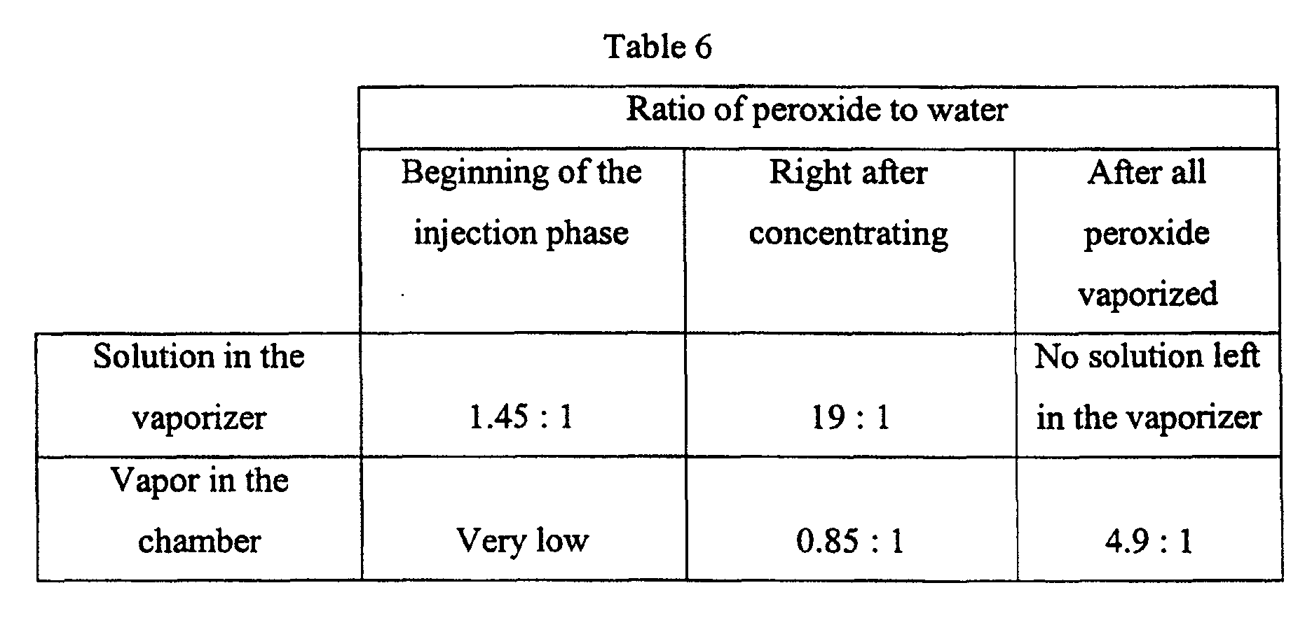 Table 8 shows the efficacy of the concentrating process with 12% peroxide solution by weight. Tests were conducted by placing one stainless steel wire inoculated with 2.1x10⁶ Bacillus stearothermophilus spores at the center of the stainless steel lumen. Four 1 mm lumens with length ranging from 250 mm to 400 mm were used for each test. The normal process was conducted by evacuating the chamber to 0.3 torr, closing the valve, injecting 7400 mg of 12% peroxide solution by weight into the vaporizer, allowing the water and peroxide to vaporize and diffuse for a total of 23 minutes, and venting the chamber. The concentrating process was conducted by evacuating the chamber to 0.3 torr, introducing 7400 mg of 12% peroxide solution by weight into the vaporizer with the valve at the open position, allowing the water and peroxide to vaporize and diffuse, closing the valve when the peroxide concentration increased to 0.45 mg/L, allowing the remaining water and peroxide to vaporize and diffuse, and venting the chamber. Due to the excess of the solution introduced into the vaporizer, the valve was remained at the open position for 16 minutes to remove enough water from the sterilizer and to concentrate the peroxide that remained in the system. The valve was then closed for an additional 7 minutes to allow the remaining peroxide to vaporize and diffuse. The total peroxide exposure time for both processes was 23 minutes. The results, as shown in the Table 8, indicate that the concentrating process is more efficacious than the normal process and diluted peroxide solution can also be used in this concentrating process. These results also indicate that monitoring the peroxide concentration in the chamber can control the concentrating process.
 The pressure and peroxide concentration curves during the concentrating process with 12% peroxide solution by weight are presented in Figure 9. The chamber was set at 45°C. The vaporizer has its own heater and is in communication with the chamber and separated from the chamber with the o-rings. Initially, the heater on the vaporizer was off and the vaporizer was heated to about 45°C due to the heated chamber and air around the vaporizer. As indicated from the pressure and peroxide concentration curves, the majority of molecules vaporized and diffused into the chamber during the first 15 minutes were water. Not much peroxide was vaporized and diffused into the chamber. This is consistent with the data published by Schumb et al., as shown in Table 9, that the concentration of hydrogen peroxide in the vapor phase over a 12% peroxide solution by weight, or 6.7% by mole, is less than 0.5% by mole under our test conditions.
- As water and peroxide vaporized from the vaporizer, the vaporizer temperature decreased more than 10°C. With the valve at the open position while water and peroxide vaporized and diffused into the chamber, more water is removed from the system than the peroxide, and the peroxide concentration left in the vaporizer is increased. As indicated from the graph, the hydrogen peroxide concentration started to increase after 15 minutes. This indicated that the peroxide solution left in the vaporizer had been concentrated by removing enough water from the vaporizer. The valve was then closed to retain the remaining peroxide vaporized into the sterilizer. The temperature of the vaporizer can then be optionally increased to enhance the vaporization of the remaining peroxide solution left in the vaporizer.
- Alternatively, the concentrating process can also be conducted by connecting the vaporizer and a vacuum pump to the chamber through a common port. As shown in FIG. 10, both a
vaporizer 92 and apump 94 are in fluid communication with achamber 90 through acommon port 91. This configuration provides the advantage over FIG. 6 of removing the water vapor during the concentrating process directly to thepump 94 without passing it through thechamber 90. By eliminating or reducing the amount of water flow into the chamber, the efficacy of peroxide can be enhanced. The extraction of air from thechamber 90 during the vaporizing process prevents the released vapors from entering the chamber and thereby obviates the need for a valve or other barrier between thevaporizer 92 and thechamber 90. - An
optional temperature controller 93 controls the rate of vaporization and anoptional valve 96 separates thepump 94 from thevaporizer 92 andchamber 90. Evacuation of thechamber 90 and thevaporizer 92 can be controlled by operation of thevalve 96 or by turning thepump 94 on or off. - Another
optional valve 98 on theport 91 can flow or bleed air into the system to create a flow fromport 91 to thepump 94. This flow hinders flow of water and peroxide from thevaporizer 92 into thechamber 90 during the concentrating process. Alternatively, anoptional pinhole 99 can be used to bleed air or gas into the system for the same purpose. Thevalve 98 orpinhole 99 can also be located on thechamber 90. - After sufficiently concentrating the hydrogen peroxide solution in the vaporizer the
pump 94 is turned off or isolated from the chamber by closing thevalve 96. The low pressure in the vaporizer vaporizes the remaining concentrated peroxide solution which then diffuses into thechamber 90 throughport 91. Methods to perform the concentrating process described in Table 1 can be applied to this apparatus to concentrate the peroxide solution. Various vaporizers, such as thevaporizer 56 of FIG. 7 or thevaporizer 76 of FIG. 8, can also be used with this apparatus to enhance the efficiency of the concentrating process. Preferably, the sterilizer comprisesvalves - In one of the many operating embodiments, the liquid hydrogen peroxide solution is first introduced into the
vaporizer 92. The liquid can be introduced with a cassette delivery system, a bulk delivery system, a syringe, or disposable cell packs or other methods appreciated by those of skill in the art. The pump is then turned on to evacuate the system. This creates two directional flows. The air in thechamber 90 flows from thechamber 90 to thepump 94, and water vapor and peroxide vapor flow from thevaporizer 92 to thepump 94. The flow of air from thechamber 90 to thepump 94 prevents or minimizes the flow of water vapor and peroxide vapor from thevaporizer 92 to thechamber 90. Since water has higher vapor pressure than the hydrogen peroxide, more water is removed from the solution than the hydrogen peroxide. The concentrating efficiency of the hydrogen peroxide solution in thevaporizer 92 can be controlled by controlling the pumping rate, the pressure, and/or the vaporizer temperature. Optionally, thevalve 98 and/or apinhole 99 can be used to further reduce or eliminate the flow of water vapor and peroxide vapor from thevaporizer 92 into thechamber 90. After the peroxide solution is concentrated to a desired concentration, thepump 94 is then turned off or thevalve 96 is then closed to allow vaporization of the remaining concentrated peroxide and water from thevaporizer 92 through theport 91 and into thechamber 90. Atemperature controller 93 located outside of thevaporizer 92 can be set at various temperatures throughout the cycle to optimize the concentrating process and the vaporization of the concentrated peroxide. - FIG. 11 illustrates an apparatus as in FIG. 10, but with two
vaporizers chamber 100 through theport 104. The second vaporizer provides additional dose of peroxide to the chamber. The peroxide solution or the source of peroxide solution can be introduced into the vaporizers at the same time or separately as needed. The vaporizer temperatures can be set differently to independently control the vaporization of the water and peroxide from each vaporizer. Optionally, avalve 105 can be used to isolate thepump 103.Optional valves pinholes vaporizers chamber 100. Optionally, avalve 107 can be used to separate thevaporizer 102 from thevaporizer 101. Depending on the need, a sterilizer can be designed to have more than two vaporizers. - The length of the concentrating process or the time to close the valve can control the final peroxide concentration or the ratio of the peroxide to the water in the chamber. Since water has a higher vapor pressure than peroxide at the same temperature, the concentration of peroxide in the vaporizer or the chamber can be increased by increasing the time of the concentrating process or by delaying the time to close the valve. This concentrating process can be conducted. with peroxide solution in the chamber and/or in the vaporizer which is in fluid communication with the chamber, and it can be enhanced if the environment, which contains the peroxide solution, is a diffusion-restricted area. Monitoring or determining the concentration of water and/or peroxide in the chamber and/or vaporizer can properly control this concentrating process. It is well known in the prior art that the concentration of peroxide is an important factor to achieve good efficacy for the vapor phase peroxide process. Based on the test results of this invention, it is believed that the ratio of peroxide to water is a critical factor in the sterilization process. By determining the concentrations of peroxide and water in the process and calculating the ratio of peroxide to water, parametric release can be achieved. By determining the vapor composition and monitoring the temperature of the peroxide solution, the concentration of the peroxide solution can be determined.
Vapor composition (mole fraction H2O2) over hydrogen peroxide water solutions Temp.
(°C)Mole Fraction Hydrogen Peroxide in Liquid 10% 20% 30% 40% 50% 60% 70% 80% 90% 0 0.2% 0.6% 1.5% 3.1% 6.0% 11.2% 20.2% 35.2% 60.0% 10 0.3% 0.8% 1.8% 3.7% 7.0% 12.8% 22.4% 38.1% 62.6% 20 0.3% 0.9% 2.0% 4.1% 7.7% 13.8% 23.8% 39.7% 64.0% 25 0.3% 1.0% 2.2% 4.4% 8.1% 14.4% 24.7% 40.7% 64.8% 30 0.3% 1.0% 2.3% 4.6% 8.5% 15.1% 25.5% 41.7% 65.6% 40 0.4% 1.2% 2.6% 5.2% 9.4% 16.3% 27.2% 43.5% 67.1% 50 0.5% 1.4% 3.0% 5.7% 10.3% 17.5% 28.7% 45.2% 68.4% 60 0.5% 1.5% 3.3% 6.3% 11.1% 18.7% 30.2% 46.8% 69.6% 70 0.6% 1.7% 3.6% 6.8% 12.0% 19.9% 31.6% 48.2% 70.7% 80 0.7% 1.9% 4.0% 7.4% 12.8% 21.0% 32.9% 49.5% 71.6% 90 0.7% 2.1% 4.3% 8.0% 13.6% 22.1% 34.2% 50.8% 72.5% 100 0.8% 2.3% 4.7% 8.5% 14.4% 23.1% 35.4% 51.9% 73.3%
Table 10A has the ratios of hydrogen peroxide to water in the vapor phase with 10%, 20% and 30% hydrogen peroxide solutions by mole under various temperatures.Ratio of peroxide to water in the vapor phase over hydrogen peroxide solutions 10% by mole or
17.3% by weight
insolution 20% by mole or
32.1% by weight
insolution 30% by mole or
44.7% by weight
in solutionTemp.
(°C)Ratio of
peroxide
to water
in vapor
by moleRatio of
peroxide
to water
in vapor
by weightRatio of
peroxide to
water
in vapor by
moleRatio of
peroxide
to water
in vapor by
weightRatio of
peroxide
to water
in vapor
by moleRatio of
peroxide
to water
in vapor
by weight0 0.0020 0.0038 0.0060 0.0114 0.0152 0.0288 10 0.0030 0.0057 0.0081 0.0152 0.0183 0.0346 20 0.0030 0.0057 0.0091 0.0172 0.0204 0.0385 25 0.0030 0.0057 0.0101 0.0191 0.0225 0.0425 30 0.0030 0.0057 0.0101 0.0191 0.0235 0.0445 40 0.0040 0.0076 0.0121 0.0229 0.0267 0.0504 50 0.0050 0.0095 0.0142 0.0268 0.0309 0.0584 60 0.0050 0.0095 0.0152 0.0288 0.0341 0.0645 70 0.0060 0.0114 0.0173 0.0327 0.0373 0.0705 80 0.0070 0.0133 0.0194 0.0366 0.0417 0.0787 90 0.0070 0.0133 0.0215 0.0405 0.0449 0.0849 100 0.0081 0.0152 0.0235 0.0445 0.0493 0.0932 Ratio of peroxide to water in the vapor phase over hydrogen peroxide solutions 40% by mole or
55.7% by weight
in solution50% by mole or
65.4% by weight
insolution 60% by mole or
73.9% by weight
in solutionTemp.
(°C)Ratio of
peroxide to
water
in vapor by
moleRatio of
peroxide to
water in vapor by weightRatio of
peroxide to
water in vapor by moleRatio of
peroxide
to water
in vapor
by weightRatio of
peroxide to
water
in vapor by
moleRatio of
peroxide to
water
in vapor by
weight0 0.0320 0.0604 0.0638 0.1206 0.1261 0.2382 10 0.0384 0.0726 0.0753 0.1422 0.1468 0.2773 20 0.0428 0.0808 0.0834 0.1576 0.1601 0.3024 25 0.0460 0.0869 0.0881 0.1665 0.1682 0.3178 30 0.0482 0.0911 0.0929 0.1755 0.1779 0.3360 40 0.0549 0.1036 0.1038 0.1960 0.1947 0.3678 50 0.0604 0.1142 0.1148 0.2169 0.2121 0.4007 60 0.0672 0.1270 0.1249 0.2358 0.2300 0.4345 70 0.0730 0.1378 0.1364 0.2576 0.2484 0.4693 80 0.0799 0.1509 0.1468 0.2773 0.2658 0.5021 90 0.0870 0.1643 0.1574 0.2973 0.2837 0.5359 100 0.0929 0.1755 0.1682 0.3178 0.3004 0.5674 Ratio of peroxide to water in the vapor phase over hydrogen peroxide solutions 70% by mole or
81.5% by weight
insolution 80% by mole or
88.3% by weight
insolution 90% by mole or
94.4% by weight
in solutionTemp.
(°C)Ratio of
peroxide to
water
in vapor by
moleRatio of
peroxide
to water
in vapor
by weightRatio of
peroxide to
water
in vapor by
moleRatio of
peroxide
to water
in vapor
by weightRatio of
peroxide to
water
in vapor by
moleRatio of
peroxide to
water
in vapor by
weight0 0.2531 0.4781 0.5432 1.0261 1.5000 2.8333 10 0.2887 0.5452 0.6155 1.1626 1.6738 3.1616 20 0.3123 0.5900 0.6584 1.2436 1.7778 3.3580 25 0.3280 0.6196 0.6863 1.2964 1.8409 3.4773 30 0.3423 0.6465 0.7153 1.3511 1.9070 3.6021 40 0.3736 0.7057 0.7699 1.4543 2.0395 3.8524 50 0.4025 0.7603 0.8248 1.5580 2.1646 4.0886 60 0.4327 0.8173 0.8797 1.6617 2.2895 4.3246 70 0.4620 0.8726 0.9305 1.7576 2.4130 4.5578 80 0.4903 0.9261 0.9802 1.8515 2.5211 4.7621 90 0.5198 0.9818 1.0325 1.9503 2.6364 4.9798 100 0.5480 1.0351 1.0790 2.0381 2.7453 5.1856 - By monitoring the concentration (i.e. the peroxide concentration or the ratio of hydrogen peroxide to water) during the sterilization cycle and controlling the timing to close the valve, it should be possible to achieve the long sought goal of parametric release. One could be assured that if the proper concentration was maintained for a sufficient period of time that a particular load of instruments placed within the
chamber 30 and sterilized according to the present invention then the process would be sufficiently predictable so as to allow the load to be released for use without further checking with a biological indicator. Typically, such processes employ a biological indicator in the load, such as with a test load of microorganisms, which is then checked to ensure that sufficient sterilization has been achieved to kill all of the test microorganisms. With parametric release the time consuming process of biological verifications can be skipped. - As described previously, shipping hydrogen peroxide solution with more than 60% by weight is regulated and can be difficult and impractical. One of the goals for this concentrating process is to concentrate the hydrogen peroxide solution in the system from less than 60% by weight to greater than 60% by weight. Therefore, more concentrated hydrogen peroxide can be generated during the process for a more efficacious cycle.
- The process may be further enhanced by admitting sufficient hydrogen peroxide into the system so as to force some of the vaporized solution to condense upon the instruments being sterilized within the system. As described above, the solution can be vaporized by admitting it into the system at any pressure above the vapor pressures of water and hydrogen peroxide in the solution and then vaporized by reducing the pressure, or by admitting the solution at a pressure substantially below its vapor pressure whereupon it will start to vaporize thus releasing gas and increasing the pressure. In the second scenario if the pressure is then further reduced by pumping down the system, the concentration of the hydrogen peroxide in the system can be increased. This is especially true if the peroxide partial pressure rises to a level at least above the equilibrium partial pressure of hydrogen peroxide thereby limiting further vaporization of hydrogen peroxide from solution and encouraging some of the hydrogen peroxide to condense upon objects such as instruments within the system. Some of the water vapor would likely also condense in such event. By controlling the pressure, excess water vapor would be exhausted from the system and then the condensed solution would re-vaporize. To the extent that such solution had condensed within diffusion restricted areas the re-vaporization therein would further increase the concentration in those areas to enhance the sterilization efficacy therein. The quantity of solution admitted will primarily determine the pressure rise to initiate such condensation. The process is described in more detail in our co-pending U.S. Application Serial No. 09/223,594 filed December 30, 1998 and entitled "Sterilization of Diffusion-Restricted Area by Re-Vaporizing the Condensed Vapor", which is incorporated herein by reference.
- A typical cycle might comprise placing a load of instruments (not shown) within a CSR (Central Supply Room) wrapped tray within the chamber 30 (as shown in FIG 6) and then drawing a vacuum on the
chamber 30 with thepump 32 down to below 1 torr or about 0.3 torr. An electromagnetic field applied to thechamber 30 at such time tends to drive any remaining water into the vapor or plasma phase so that thepump 32 can remove it. Thepump 32 can be cycled or merely run continuously with thevalve 34 controlling the vacuum process. Fresh dry air may be admitted to thechamber 30 raising the pressure back to atmosphere. Preferably the hydrogen peroxide solution, preferably a 59% hydrogen peroxide solution by weight, is admitted to thevaporizer 36 at atmospheric pressure and then thepump 32 exhausts thechamber 30 to a level at which the solution begins to vaporize. Asensor 120 for hydrogen peroxide vapor and sensor 122 (see FIG. 6) for water vapor in connection with anautomated control system 124 can be employed to optimize the pressure conditions to enhance the initial vaporization and exhaust of water vapor. After the solution is sufficiently concentrated the temperature of thevaporizer 36 can be increased to rapidly vaporize the remaining solution. Thevalve 32 is closed to isolate thechamber 30 and the vaporized hydrogen peroxide solution is allowed to diffuse throughout the chamber to contact the instruments. Additional dry air or other gas can be admitted at this time to help push the sterilizing vapors into diffusion restricted areas, with thechamber 30 then further exhausted to resume a vacuum in the range of 2 to 10 torr. Additional admissions of air and vacuum can be employed, especially in connection with additional admission and concentration of hydrogen peroxide solutions. After the hydrogen peroxide vapors have diffused throughout the chamber for a sufficient time an electromagnetic field may be applied to drive the vapor into the plasma phase and effect further sterilization. When the field is removed the activated species formed from the hydrogen peroxide recombine as water and oxygen, leaving little residual hydrogen peroxide. The chamber can be raised to atmospheric pressure and the load removed. - It should be noted that the present invention is not limited to only those embodiments described in the Detailed Description. Any embodiment which retains the spirit of the present invention should be considered to be within its scope. However, the invention is only limited by the scope of the following claims.
Claims (30)
- A method of sterilizing an article comprising the steps of:placing the article into a chamber containing an inner atmosphere;introducing a solution comprising hydrogen peroxide and water into a vaporizer in fluid communication with the chamber through a port, the solution having a ratio of hydrogen peroxide to water;pumping a portion of the inner atmosphere out of the chamber through the port thereby reducing pressure in the chamber and in the vaporizer;vaporizing water vapor out of the solution;drawing the water vapor from the vaporizer to increase the ratio of hydrogen peroxide to water in the vaporizer;terminating the pumping step without terminating the vaporizing steps;vaporizing hydrogen peroxide vapor out of the solution and flowing the hydrogen peroxide vapor from the vaporizer into the chamber; andcontacting the article with the hydrogen peroxide vapor for a time period sufficient to effect sterilization of the article.
- A method according to claim 1 wherein the ratio of hydrogen peroxide to water in said solution, by weight, after the step of drawing water vapor from the vaporizer exceeds 3 to 1.
- A method according to claim 2 wherein the ratio of hydrogen peroxide to water in said solution, by weight, is less than 3:2 before the step of drawing water vapor from the vaporizer.
- A method according to claim 2 wherein the ratio of hydrogen peroxide to water in said solution, by weight, after the step of drawing water vapor from the vaporizer exceeds 4 to 1.
- A method according to claim 1 wherein the step of drawing water vapor from the vaporizer comprises introducing said solution within a diffusion restricted environment in fluid communication with the chamber during the step of vaporizing the solution.
- A method according to claim 5 wherein the diffusion restricted environment is more diffusion restricted during the step of drawing water vapor from the vaporizer than during a portion of the step of flowing the hydrogen peroxide vapor from the vaporizer into the chamber.
- A method according to claim 1 wherein at least a portion of the pumping step and the vaporizing step occur simultaneously.
- A method according to claim 1 wherein at least a portion of the pumping step, the vaporizing step and the drawing step occur simultaneously.
- A method according to claim 1 wherein the step of drawing water vapor from the vaporizer comprises the step of maintaining the solution at a pressure below the vapor pressure of the water in the solution and above the vapor pressure of the hydrogen peroxide in the solution.
- A method according to claim 1 wherein the solution is vaporized by pumping a portion of the atmosphere out of the vaporizer to lower the pressure at a rate selected to control removal of the water and hydrogen peroxide from the solution so as to concentrate the hydrogen peroxide remaining in the vaporizer.
- A method according to claim 1 wherein the temperature of the solution during the vaporizing step is held below the temperature of the atmosphere in the chamber whereby to increase the vapor pressure of the water in the solution relative to the hydrogen peroxide in the solution whereby to enhance vaporization of the water from the solution in preference to vaporizing the hydrogen peroxide from the solution.
- A method according to claim 11 wherein the temperature of the atmosphere in the chamber is above room temperature and the temperature of the solution during the vaporizing step is at least 10° C below the temperature of the atmosphere in the chamber.
- A method according to claim 11 wherein the solution is vaporized in a vaporizer which is in fluid communication with the chamber and wherein the vaporizer is thermally isolated from the chamber.
- A method according to claim 1 and further comprising the steps of controlling the temperature and pressure of the solution during a least a first portion of the vaporizing step so as to vaporize water from the solution and concentrate hydrogen peroxide therein to form a concentrated solution and during the step of vaporizing hydrogen peroxide out of the solution raising the temperature of the concentrated solution and vaporizing the concentrated solution.
- A method according to claim 1 wherein the step of contacting the article with the hydrogen peroxide vapor is limited to less than one hour and if the article were to have a straight round lumen having two open ends, a diameter of 1mm and a length of 250mm with 106 viable spores of B. Stearothermophilus located within the lumen at a midpoint thereof, all of the spores would be killed.
- A method according to claim 1 wherein the solution comprises peracetic acid.
- A method according to claim 1 wherein the step of introducing the solution comprising hydrogen peroxide and water into vaporizer occurs at atmospheric pressure.
- A method according to claim 1 wherein the step of introducing the solution comprising hydrogen peroxide and water into vaporizer occurs at the vapor pressure of said solution.
- A method according to claim 1 wherein the step of introducing the solution comprising hydrogen peroxide and water into vaporizer occurs below the vapor pressure of said solution.
- A method according to claim 1 and further comprising the step of bleeding air into said port from exterior of the chamber.
- A method according to claim 20 wherein said air is bled into the port from a location between the vaporizer and the chamber.
- A method according to claim 1 wherein the step of terminating the pumping step comprises closing fluid communication between the pump and the port.
- A method according to claim 1 and further comprising a flow stream defined between the chamber and the pump and wherein the vaporizer is located along the flow stream between the chamber and the pump.
- An apparatus for sterilizing an article with a concentrated hydrogen peroxide vapor, the apparatus comprising:a source of liquid germicide comprising hydrogen peroxide;a chamber adapted to receive the article, wherein said chamber has a port;a first vaporizer in fluid communication with the chamber through the port; anda pump in fluid communication with the chamber through the port.
- An apparatus according to claim 24 and further comprising a valve located to isolate the pump from the chamber and the vaporizer.
- An apparatus according to claim 24 and further comprising an inlet to bleed air into the apparatus, and wherein the inlet is located either in the chamber or between the vaporizer and the chamber.
- An apparatus according to claim 26 wherein the inlet comprises a valve.
- An apparatus according to claim 24 and further comprising a second vaporizer in fluid communication with the chamber through the port.
- An apparatus according to claim 28 and further comprising a valve between the first vaporizer and the second vaporizer, to isolate the second vaporizer from the first vaporizer.
- An apparatus according to claim 28 and further comprising an inlet located between the first vaporizer and the second vaporizer, to bleed air into the apparatus.
Applications Claiming Priority (2)
| Application Number | Priority Date | Filing Date | Title |
|---|---|---|---|
| US8017 | 2001-11-05 | ||
| US10/008,017 US20030124026A1 (en) | 2001-11-05 | 2001-11-05 | Apparatus and process for concentrating a sterilant and sterilizing articles therewith |
Publications (2)
| Publication Number | Publication Date |
|---|---|
| EP1308173A1 true EP1308173A1 (en) | 2003-05-07 |
| EP1308173B1 EP1308173B1 (en) | 2008-12-24 |
Family
ID=21729369
Family Applications (1)
| Application Number | Title | Priority Date | Filing Date |
|---|---|---|---|
| EP02257623A Expired - Lifetime EP1308173B1 (en) | 2001-11-05 | 2002-11-04 | Apparatus and process for concentrating a sterilant and sterilizing articles with the concentrated sterilant |
Country Status (8)
| Country | Link |
|---|---|
| US (1) | US20030124026A1 (en) |
| EP (1) | EP1308173B1 (en) |
| JP (1) | JP4421181B2 (en) |
| KR (1) | KR20030038428A (en) |
| AU (1) | AU2002301749B2 (en) |
| CA (1) | CA2411099A1 (en) |
| DE (1) | DE60230474D1 (en) |
| ES (1) | ES2317981T3 (en) |
Cited By (4)
| Publication number | Priority date | Publication date | Assignee | Title |
|---|---|---|---|---|
| KR20030038428A (en) * | 2001-11-05 | 2003-05-16 | 에디컨인코포레이티드 | Apparatus and process for concentrating a sterilant and sterilizing articles therewith |
| WO2012003903A1 (en) * | 2010-07-09 | 2012-01-12 | Khs Gmbh | Method and system for disinfecting and sterilizing hollow bodies |
| WO2014020448A3 (en) * | 2012-08-02 | 2014-07-03 | Goa Teknoloji Danişmanlik Elektronik, Imalat Ticaret Ithalat Ihracat A. Ş. | Multi mode low temperature hydrogen peroxide sterilizer |
| WO2020002989A1 (en) * | 2018-06-29 | 2020-01-02 | Asp Global Manufacturing Gmbh | Method and apparatus for cleaning, disinfection, sterilization, or combinations thereof |
Families Citing this family (14)
| Publication number | Priority date | Publication date | Assignee | Title |
|---|---|---|---|---|
| US7569180B2 (en) * | 2004-10-12 | 2009-08-04 | Ethicon, Inc. | Sterilization system and method and orifice inlet control apparatus therefor |
| ES2398533T3 (en) | 2005-08-04 | 2013-03-20 | Saban Ventures Pty Limited | Disinfection of spaces |
| US20070098591A1 (en) * | 2005-10-31 | 2007-05-03 | Georg Frinke | Method and apparatus for low energy vaporization of liquid oxidizing agents or solutions |
| WO2007070922A1 (en) * | 2005-12-21 | 2007-06-28 | Gary Erickson | In-situ continuous enclosed or semi-enclosed space sanitation and deodorization |
| JP5467868B2 (en) * | 2007-02-02 | 2014-04-09 | サバン ヴェンチャーズ ピーティーワイ リミテッド | Membrane vapor concentrator |
| KR100840254B1 (en) * | 2008-01-28 | 2008-06-20 | 주식회사 바이오미스트테크놀로지 | Disinfection equipment for records and artifacts, sterilization methods using the same |
| KR20110044856A (en) * | 2008-06-30 | 2011-05-02 | 써번 벤쳐스 피티와이 리미티드 | Aerosol sensor |
| US8889081B2 (en) | 2009-10-15 | 2014-11-18 | Medivators Inc. | Room fogging disinfection system |
| EP2506884B1 (en) | 2009-12-03 | 2015-02-18 | Minntech Corporation | Container for decontaminating a medical device with a fog |
| JP5610186B2 (en) * | 2009-12-17 | 2014-10-22 | 日揮ユニバーサル株式会社 | Hydrogen peroxide gas generator |
| US9364571B2 (en) * | 2011-04-01 | 2016-06-14 | Goa Teknoloji Danismanlik Elektronik, Imalat Ticaret Ithalat Ihracat A.S. | Sterilization with in-line concentrating and injection of hydrogen peroxide |
| CN103702689B (en) * | 2011-05-27 | 2016-08-17 | 马尔科尔净化装置公司 | Cleaning system including the environmental Kuznets Curves using cleaning of substances |
| JP2013081562A (en) * | 2011-10-06 | 2013-05-09 | Canon Marketing Japan Inc | Sterilization apparatus and sterilization method |
| ES2833399T3 (en) | 2014-03-18 | 2021-06-15 | Coolsan Hygiene Solutions Pty Ltd | Product and procedure for generating hydrogen peroxide vapor |
Citations (2)
| Publication number | Priority date | Publication date | Assignee | Title |
|---|---|---|---|---|
| US4744951A (en) * | 1983-11-07 | 1988-05-17 | American Sterilizer Company | Vaporization method to enhance sterilant penetration |
| WO2000038745A1 (en) * | 1998-12-30 | 2000-07-06 | Ethicon, Inc. | A method of sterilizing an article and certifying the article as sterile |
Family Cites Families (22)
| Publication number | Priority date | Publication date | Assignee | Title |
|---|---|---|---|---|
| US3489505A (en) * | 1967-08-28 | 1970-01-13 | Hugo Sonnenschein | Sterilizing apparatus |
| US3490863A (en) * | 1967-09-18 | 1970-01-20 | Hugo Sonnenschein | Sterilizing system and method |
| US4169123A (en) * | 1975-12-11 | 1979-09-25 | Moore-Perk Corporation | Hydrogen peroxide vapor sterilization method |
| US4169124A (en) * | 1977-09-26 | 1979-09-25 | Moore-Perk Corporation | Cold gas sterilization process |
| US4642165A (en) * | 1984-12-21 | 1987-02-10 | American Sterilizer Company | Method of vaporizing multicomponent liquids |
| US4643876A (en) * | 1985-06-21 | 1987-02-17 | Surgikos, Inc. | Hydrogen peroxide plasma sterilization system |
| US4899519A (en) * | 1987-05-20 | 1990-02-13 | Surgikos, Inc. | Fluid injection system cassette and fluid packaging methods |
| US4817800A (en) * | 1987-05-20 | 1989-04-04 | Surgikos, Inc. | Fluid injection system cassette and fluid packaging methods |
| US4943414A (en) * | 1987-07-30 | 1990-07-24 | Johnson & Johnson Medical, Inc. | Method for vapor sterilizaton of articles having lumens |
| US4952370A (en) * | 1988-05-06 | 1990-08-28 | American Sterilizer Company | Hydrogen peroxide sterilization method |
| US5173258A (en) * | 1989-10-11 | 1992-12-22 | American Sterilizer Company | Recirculation, vapor and humidity control in a sealable enclosure |
| EP0583465A1 (en) * | 1992-03-13 | 1994-02-23 | American Sterilizer Company | Sterilization apparatus and method for multicomponent sterilant |
| US5656238A (en) * | 1994-10-11 | 1997-08-12 | Johnson & Johnson Medical, Inc. | Plasma-enhanced vacuum drying |
| BE1009410A3 (en) * | 1995-06-14 | 1997-03-04 | B C A Sa | Device heat transport. |
| US5906794A (en) * | 1995-06-15 | 1999-05-25 | American Sterilizer Company | Continuous-operation, closed loop decontamination system and method |
| US6030579A (en) * | 1996-04-04 | 2000-02-29 | Johnson & Johnson Medical, Inc. | Method of sterilization using pretreatment with hydrogen peroxide |
| US5876664A (en) * | 1996-06-14 | 1999-03-02 | American Sterilizer Company | Continuous-operation, closed loop decontamination system and method |
| US5792422A (en) * | 1996-12-20 | 1998-08-11 | Ethicon, Inc. | Liquid/vapor sterilization container systems |
| US5851485A (en) * | 1996-12-20 | 1998-12-22 | Johnson & Johnson Medical, Inc. | Process for sterilization with liquid sterilant using controlled pumpdown rate |
| US5804139A (en) * | 1996-12-20 | 1998-09-08 | Ethicon, Inc. | Two-step sterilization process using liquid sterilant |
| US6451254B1 (en) * | 1998-12-30 | 2002-09-17 | Ethicon, Inc. | Sterilization of diffusion-restricted area by revaporizing the condensed vapor |
| US20030124026A1 (en) * | 2001-11-05 | 2003-07-03 | Hal Williams | Apparatus and process for concentrating a sterilant and sterilizing articles therewith |
-
2001
- 2001-11-05 US US10/008,017 patent/US20030124026A1/en not_active Abandoned
-
2002
- 2002-10-31 AU AU2002301749A patent/AU2002301749B2/en not_active Ceased
- 2002-11-01 JP JP2002320322A patent/JP4421181B2/en not_active Expired - Lifetime
- 2002-11-04 EP EP02257623A patent/EP1308173B1/en not_active Expired - Lifetime
- 2002-11-04 CA CA002411099A patent/CA2411099A1/en not_active Abandoned
- 2002-11-04 DE DE60230474T patent/DE60230474D1/en not_active Expired - Lifetime
- 2002-11-04 ES ES02257623T patent/ES2317981T3/en not_active Expired - Lifetime
- 2002-11-05 KR KR1020020068110A patent/KR20030038428A/en not_active Ceased
Patent Citations (3)
| Publication number | Priority date | Publication date | Assignee | Title |
|---|---|---|---|---|
| US4744951A (en) * | 1983-11-07 | 1988-05-17 | American Sterilizer Company | Vaporization method to enhance sterilant penetration |
| WO2000038745A1 (en) * | 1998-12-30 | 2000-07-06 | Ethicon, Inc. | A method of sterilizing an article and certifying the article as sterile |
| WO2000038746A1 (en) * | 1998-12-30 | 2000-07-06 | Ethicon, Inc. | Process for concentrating a sterilant and sterilizing articles therewith |
Cited By (5)
| Publication number | Priority date | Publication date | Assignee | Title |
|---|---|---|---|---|
| KR20030038428A (en) * | 2001-11-05 | 2003-05-16 | 에디컨인코포레이티드 | Apparatus and process for concentrating a sterilant and sterilizing articles therewith |
| WO2012003903A1 (en) * | 2010-07-09 | 2012-01-12 | Khs Gmbh | Method and system for disinfecting and sterilizing hollow bodies |
| WO2014020448A3 (en) * | 2012-08-02 | 2014-07-03 | Goa Teknoloji Danişmanlik Elektronik, Imalat Ticaret Ithalat Ihracat A. Ş. | Multi mode low temperature hydrogen peroxide sterilizer |
| WO2020002989A1 (en) * | 2018-06-29 | 2020-01-02 | Asp Global Manufacturing Gmbh | Method and apparatus for cleaning, disinfection, sterilization, or combinations thereof |
| US11951223B2 (en) | 2018-06-29 | 2024-04-09 | Asp Global Manufacturing Gmbh | Method and apparatus for cleaning, disinfection, sterilization, or combinations thereof |
Also Published As
| Publication number | Publication date |
|---|---|
| ES2317981T3 (en) | 2009-05-01 |
| DE60230474D1 (en) | 2009-02-05 |
| KR20030038428A (en) | 2003-05-16 |
| US20030124026A1 (en) | 2003-07-03 |
| JP2003180802A (en) | 2003-07-02 |
| EP1308173B1 (en) | 2008-12-24 |
| CA2411099A1 (en) | 2003-05-05 |
| AU2002301749B2 (en) | 2008-04-24 |
| JP4421181B2 (en) | 2010-02-24 |
Similar Documents
| Publication | Publication Date | Title |
|---|---|---|
| AU755983C (en) | A method of sterilizing an article and certifying the article as sterile | |
| AU2002301749B2 (en) | Apparatus and process for concentrating a sterilant and sterilizing articles therewith | |
| JP4722660B2 (en) | Sterilization system and method and orifice control apparatus therefor | |
| JP4739130B2 (en) | Sterilization system and vaporizer | |
| US5851485A (en) | Process for sterilization with liquid sterilant using controlled pumpdown rate | |
| US6528016B1 (en) | Method for rapidly determining the acceptability of loads to be sterilized | |
| JP4480961B2 (en) | Sterilization method by flow in container | |
| JP2007296325A (en) | Method and apparatus for prion deactivation | |
| JP4302237B2 (en) | Two-step sterilization method using liquid sterilant | |
| US20130236359A1 (en) | Methods for sterilization in a vacuum system |
Legal Events
| Date | Code | Title | Description |
|---|---|---|---|
| PUAI | Public reference made under article 153(3) epc to a published international application that has entered the european phase |
Free format text: ORIGINAL CODE: 0009012 |
|
| AK | Designated contracting states |
Designated state(s): AT BE BG CH CY CZ DE DK EE ES FI FR GB GR IE IT LI LU MC NL PT SE SK TR |
|
| AX | Request for extension of the european patent |
Extension state: AL LT LV MK RO SI |
|
| 17P | Request for examination filed |
Effective date: 20031020 |
|
| AKX | Designation fees paid |
Designated state(s): DE ES FR GB IT |
|
| 17Q | First examination report despatched |
Effective date: 20040806 |
|
| GRAP | Despatch of communication of intention to grant a patent |
Free format text: ORIGINAL CODE: EPIDOSNIGR1 |
|
| GRAS | Grant fee paid |
Free format text: ORIGINAL CODE: EPIDOSNIGR3 |
|
| GRAA | (expected) grant |
Free format text: ORIGINAL CODE: 0009210 |
|
| AK | Designated contracting states |
Kind code of ref document: B1 Designated state(s): DE ES FR GB IT |
|
| REG | Reference to a national code |
Ref country code: GB Ref legal event code: FG4D |
|
| REF | Corresponds to: |
Ref document number: 60230474 Country of ref document: DE Date of ref document: 20090205 Kind code of ref document: P |
|
| REG | Reference to a national code |
Ref country code: ES Ref legal event code: FG2A Ref document number: 2317981 Country of ref document: ES Kind code of ref document: T3 |
|
| PLBE | No opposition filed within time limit |
Free format text: ORIGINAL CODE: 0009261 |
|
| STAA | Information on the status of an ep patent application or granted ep patent |
Free format text: STATUS: NO OPPOSITION FILED WITHIN TIME LIMIT |
|
| 26N | No opposition filed |
Effective date: 20090925 |
|
| REG | Reference to a national code |
Ref country code: FR Ref legal event code: PLFP Year of fee payment: 15 |
|
| REG | Reference to a national code |
Ref country code: FR Ref legal event code: PLFP Year of fee payment: 16 |
|
| REG | Reference to a national code |
Ref country code: FR Ref legal event code: PLFP Year of fee payment: 17 |
|
| PGFP | Annual fee paid to national office [announced via postgrant information from national office to epo] |
Ref country code: DE Payment date: 20191127 Year of fee payment: 18 |
|
| REG | Reference to a national code |
Ref country code: GB Ref legal event code: 732E Free format text: REGISTERED BETWEEN 20200109 AND 20200115 |
|
| PGFP | Annual fee paid to national office [announced via postgrant information from national office to epo] |
Ref country code: IT Payment date: 20191125 Year of fee payment: 18 Ref country code: FR Payment date: 20191125 Year of fee payment: 18 Ref country code: ES Payment date: 20191202 Year of fee payment: 18 |
|
| REG | Reference to a national code |
Ref country code: DE Ref legal event code: R119 Ref document number: 60230474 Country of ref document: DE |
|
| PG25 | Lapsed in a contracting state [announced via postgrant information from national office to epo] |
Ref country code: FR Free format text: LAPSE BECAUSE OF NON-PAYMENT OF DUE FEES Effective date: 20201130 Ref country code: IT Free format text: LAPSE BECAUSE OF NON-PAYMENT OF DUE FEES Effective date: 20201104 |
|
| PG25 | Lapsed in a contracting state [announced via postgrant information from national office to epo] |
Ref country code: DE Free format text: LAPSE BECAUSE OF NON-PAYMENT OF DUE FEES Effective date: 20210601 |
|
| PGFP | Annual fee paid to national office [announced via postgrant information from national office to epo] |
Ref country code: GB Payment date: 20211129 Year of fee payment: 20 |
|
| REG | Reference to a national code |
Ref country code: ES Ref legal event code: FD2A Effective date: 20220131 |
|
| PG25 | Lapsed in a contracting state [announced via postgrant information from national office to epo] |
Ref country code: ES Free format text: LAPSE BECAUSE OF NON-PAYMENT OF DUE FEES Effective date: 20201105 |
|
| REG | Reference to a national code |
Ref country code: GB Ref legal event code: PE20 Expiry date: 20221103 |
|
| PG25 | Lapsed in a contracting state [announced via postgrant information from national office to epo] |
Ref country code: GB Free format text: LAPSE BECAUSE OF EXPIRATION OF PROTECTION Effective date: 20221103 |