EP1308137A2 - System and means for mixing impression materials for dentistry applications and the like - Google Patents
System and means for mixing impression materials for dentistry applications and the like Download PDFInfo
- Publication number
- EP1308137A2 EP1308137A2 EP02024904A EP02024904A EP1308137A2 EP 1308137 A2 EP1308137 A2 EP 1308137A2 EP 02024904 A EP02024904 A EP 02024904A EP 02024904 A EP02024904 A EP 02024904A EP 1308137 A2 EP1308137 A2 EP 1308137A2
- Authority
- EP
- European Patent Office
- Prior art keywords
- mixing
- mixing unit
- outlet
- compound
- ring gear
- Prior art date
- Legal status (The legal status is an assumption and is not a legal conclusion. Google has not performed a legal analysis and makes no representation as to the accuracy of the status listed.)
- Granted
Links
Images




Classifications
-
- A—HUMAN NECESSITIES
- A61—MEDICAL OR VETERINARY SCIENCE; HYGIENE
- A61C—DENTISTRY; APPARATUS OR METHODS FOR ORAL OR DENTAL HYGIENE
- A61C9/00—Impression cups, i.e. impression trays; Impression methods
- A61C9/0026—Syringes or guns for injecting impression material; Mixing impression material for immediate use
-
- B—PERFORMING OPERATIONS; TRANSPORTING
- B05—SPRAYING OR ATOMISING IN GENERAL; APPLYING FLUENT MATERIALS TO SURFACES, IN GENERAL
- B05C—APPARATUS FOR APPLYING FLUENT MATERIALS TO SURFACES, IN GENERAL
- B05C17/00—Hand tools or apparatus using hand held tools, for applying liquids or other fluent materials to, for spreading applied liquids or other fluent materials on, or for partially removing applied liquids or other fluent materials from, surfaces
- B05C17/005—Hand tools or apparatus using hand held tools, for applying liquids or other fluent materials to, for spreading applied liquids or other fluent materials on, or for partially removing applied liquids or other fluent materials from, surfaces for discharging material from a reservoir or container located in or on the hand tool through an outlet orifice by pressure without using surface contacting members like pads or brushes
- B05C17/00503—Details of the outlet element
- B05C17/00516—Shape or geometry of the outlet orifice or the outlet element
Definitions
- These mixtures comprise alginate mixtures and plaster mixtures: the former are used usually in dentists' surgeries as impression material and the latter are instead used in dental laboratories to produce the models.
- silicone-based impression materials which are constituted by a gelatinous base and by a more or less fluid catalyst and must be mixed at the time of use because their compound, too, cures rather rapidly.
- the gelatinous base and the catalyst are often packaged so that they pass directly and simultaneously from their respective containers into a sort of spiral nozzle and arrive at the outlet already mixed by simply passing through said nozzle.
- the aim of the present invention is to solve the practical and economic problems noted above.
- the system that has been devised is in fact based mainly on the use of mixing units, which are interchangeable and reusable and are filled at the appropriate time with a specific quantity of the component in powder form to be mixed or of the gelatinous base to be catalyzed, so that they can be used when necessary, one at a time, in an apparatus that automatically adds thereto.
- the water-based solution or catalyst required mixes all the components by moving the rotary agitator with which said mixing unit is provided, opens the outlet of the unit and expels from said unit all of the compound by acting on a sort of plunger which also belongs to the mixing unit and is capable of freeing of any residue the agitators and the entire mixing chamber.
- the container 2 which has a constant cross-section in an intermediate region 2B that covers most of its height, has a wider portion 2A in the upper edge for the closing resting of the rotary agitator 1, and in a lower region has a frustum-shaped tapered portion 2C, which ends in an outlet 2D, which faces the center of a transverse guide 2E of the closure element 3, whose linear movements in either direction allow if necessary to open the outlet 2D, aligning with it, as shown in Figure 7, one of two connectors 3B arranged at the two ends of a flat portion 3A that allows closure and from which a grip portion 3C, on which one can act to perform said movements automatically, protrudes centrally downward.
- the collar that protrudes outside the container 2 at the wider portion 2A of the upper edge is the collar that allows to rest the mixing unit in a slider 6, where it remains inserted throughout the working cycle, with the container 2 furthermore necessarily motionless during the rotation of the agitator 1 and with the transverse guide 2E orientated so that the grip portion 3C of the element 3 is engaged by the actuation means designed to open and close automatically the outlet 2D.
- the rotary agitator 1 is constituted by a plastic body, from which the teeth of the ring gear 1A protrude radially and from which a plurality of mixing rods 1B, preferably made of stainless steel and used to amalgamate the two or more components, protrude downward parallel to the rotation axis and down to a frustum-shaped bottom 26 of the container.
- a plunger is associated with the agitator 1; since it must subsequently expel the mixed compound, the plunger is constituted by a rigid body 4 that is covered in a lower region by a liner 5 made of silicone or other elastic material that can be sterilized in an autoclave.
- Both the rigid body 4 and the elastic liner 5 are crossed, in the respective holes 4D and 5A, by the rods 1B, which they follow in their mixing movement and then clean, together with the walls of the mixing chamber, in descending toward the underlying outlet 2D of the container 2.
- a sort of capsule 4A which has a circular cross-section protrudes centrally from the two faces of the disk-like portion 4B of the rigid body 4 and at right angles to them, and is designed to accommodate a hollow stem 15, which arrives thereat from the hole 1C of the agitator and which, before imparting to the plunger 4-5 the axial thrust required to expel the mixed compound, assists the mixing process by acting as a pivot for the agitator 1 and by introducing the water-based solution or catalyst directly in the mixing chamber, which it reaches by crossing, with its own nozzle or tip 16, the hole 4C located in the bottom of the capsule 4A and the corresponding cross-shaped slit 5B provided in the liner 5 made of elastic material.
- the elastic liner 5 also is frustum-shaped in a lower region, but as shown in Figure 7 it tapers less than the bottom of the container 2, so as to rest against it starting from the peripheral region and continue from there, by elastic deformation, gradually toward the center, where there is the outlet 2D, to which the material to be expelled is thus to be conveyed.
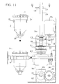
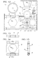
- the mixing units which as mentioned are filled in due time with a specific quantity of the component in powder form to be mixed or of the gelatinous base to be catalyzed, reach the treatment station of the automated mixing apparatus ( Figures 11 to 15) by being conveyed one at a time by the transfer slider 6, which is supported by the horizontal guides 7 and 9, to which it is rigidly coupled, the second guide being a screw that is rigidly coupled to the ring gear 10, which is meshed stably with the ring gear 11 of the electric gearmotor M1, whose rotations determine the transfer of the slider in both directions by way of the linear translational motions of the female thread 8 arranged in a corresponding recess of said slider during its insertion on the threaded guide 9.
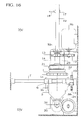
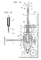
- the mixing unit can receive the hollow stem 15 which, being threaded but prevented from rotating by the pair of raised portions 17 that are rigidly coupled thereto and engaged in suitable longitudinal slots of the guide 19 fixed to the bracket 20, descends from the position of Figure 18 to the position of Figure 20, by way of the rotations in this direction of the female thread 14, which is supported in the bracket 20 between two axial bearings and is rigidly coupled to the ring gear 13, which meshes stably with the ring gear 12 of the electric gearmotor M2, whose first intervention ceases when the tip 16 of the hollow stem 15 enters the mixing chamber ( Figure 20), where the water-based solution or fluid catalyst that arrives from the flexible duct 18 is introduced in addition to the product in powder form or the gelatinous base that is already present in the mixing unit.
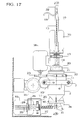
- the ring gear 24 of the gearmotor M4 ( Figure 20) is in fact meshed stably with a ring gear 25 that is coaxially rigidly coupled to the female thread 26, which is interposed between two axial bearings in the rigid support 27 and is crossed longitudinally by a screw 30 that has, at one end, a pair of wings 31, which form the means for opening and closing the outlet 2D, with which the grip portion 3C of the element 3 is to be engaged; two raised portions 29 protrude from the other end and, being engaged in suitable longitudinal slots of the guide 28 that protrudes from the support 27, force the spring 30 to perform an axial translational motion in either direction depending on the rotation of the female thread 26.
- the apparatus After completing the expulsion of the entire compound, freshly mixed and designed to be used immediately, the apparatus automatically activates the electric gearmotor M4, so that again by way of the female thread 26 the closure element 3 returns from the position of Figure 22 to the position of Figure 17, this being useful to facilitate the subsequent removal of the empty mixing unit from the transfer slider 6 but being most of all necessary so that the grip portion 3C of the new mixing unit can then be inserted between the two wings 31.
- the coupling located at the upper end of the hollow stem 15 and provided with the insertion of the duct 18 at one of the two raised portions 17 engaged in the longitudinal slots of the guide 19 is closed in an upper region by a portion 34 made of rubber or other material suitable to form a seal on the needle 33, which is fixed at 32 to the top of the guide 19 and, when the hollow stem 15 is at the upper stroke limit ( Figure 18), enters the stem and the corresponding tip 16, from which it protrudes, with the end of the suitably tapered end portion, enough to avoid protruding from the presser ring 22.
- alternating linear movement of the slider 6 the movement of a carousel, which is formed by a set of mixing units arranged in the peripheral seats of a rotating disk or in the carriages of a motorized circuit that passes through a treatment station such as the one already described and replaces mechanically each used mixing unit and also, in some systems, subsequently transfers them to other stations equipped to perform automatically washing, sterilization and filling with further doses of material to be mixed.
- a carousel which is formed by a set of mixing units arranged in the peripheral seats of a rotating disk or in the carriages of a motorized circuit that passes through a treatment station such as the one already described and replaces mechanically each used mixing unit and also, in some systems, subsequently transfers them to other stations equipped to perform automatically washing, sterilization and filling with further doses of material to be mixed.
Landscapes
- Health & Medical Sciences (AREA)
- General Health & Medical Sciences (AREA)
- Dentistry (AREA)
- Epidemiology (AREA)
- Life Sciences & Earth Sciences (AREA)
- Animal Behavior & Ethology (AREA)
- Oral & Maxillofacial Surgery (AREA)
- Public Health (AREA)
- Veterinary Medicine (AREA)
- Mixers Of The Rotary Stirring Type (AREA)
- Dental Preparations (AREA)
- Dental Tools And Instruments Or Auxiliary Dental Instruments (AREA)
- Materials For Medical Uses (AREA)
- Mixers With Rotating Receptacles And Mixers With Vibration Mechanisms (AREA)
Abstract
Description
- the meshing of the
ring gear 1A of therotary agitator 1 in thering gear 23 of the electric gearmotor M3 meant to move the mixing rods; - the insertion of the central grip portion 3C of the
closure element 3 between the twowings 31 of the automatic actuation device; - the positioning of the
rotary agitator 1 under thepresser ring 22, which by being pushed by theelastic lamina 21 and guided by thetubular element 35 fixed to thebracket 20 coaxially to thestem 15 keeps the agitator correctly inserted on thecontainer 2 and consequently meshed in thering gear 23.
Claims (22)
- A system for mixing impression materials for dental use and the like, characterized in that it comprises mixing units (1, 2), which are interchangeable and reusable and are filled at the appropriate time with part of the components to be mixed, particularly the components in powder form or the gelatinous components, said mixing units being used when necessary, one at a time, in an apparatus (6, 15) that automatically adds thereto the necessary fluid components, mixes all the components by moving the rotary agitator (1) with which said mixing unit (1, 2) is provided, opens the outlet (2D) of the unit and expels from said unit all of the compound by acting on a plunger (4, 5) which also belongs to the mixing unit and is capable of freeing of any residue the agitators (1B) and the entire mixing chamber (2).
- The system according to claim 1, characterized in that each mixing unit is constituted by a container (2) that has a circular cross-section and is closed in a lower region by a slide-valve element (3) and in an upper region by a rotary agitator (1) from which the teeth of a ring gear (1A) required for its actuation protrude radially and from which a plurality of rigid rods (1B) protrude downward to the bottom of the container (2), said rods constituting the agitators by means of which the components present in the mixing chamber are to be amalgamated.
- The system according to the preceding claims, characterized in that a plunger (4, 5) is associated with the rigid rods (1B), which are parallel to the rotation axis of the agitator (1), said plunger being crossed longitudinally by said rods (1B), which it follows in their rotary motion and along which it then descends in order to expel the compound through the appropriately provided discharge hole (2D) located in the bottom of the container (2).
- The system according to the preceding claims, characterized in that the plunger is constituted by a rigid body (4) that is covered, in a lower region, by a liner (5) made of silicone or other elastic material that can be sterilized in an autoclave, and is preset so that a hollow stem (15) of the apparatus, designed to give it the thrust required to expel the mixed compound, can pass initially through it longitudinally with its nozzle or tip (16), which introduces the necessary component in the mixing chamber.
- The system according to the preceding claims, characterized in that in order to achieve the expulsion of all of the mixed compound, the bottom of the container (2) and the upper part of the plunger are both frustum-shaped, but the bottom of the container (2) has a different and greater taper, so that the plunger (4, 5) can rest against it starting from the peripheral region and from there continue gradually, by elastic deformation, toward the center, where there is the discharge hole (2D), to which the material to be expelled is thus to be guided.
- The system according to the preceding claims, characterized in that the discharge hole (2D) of the mixing unit (1, 2) faces the center of a guide (2E) of the closure element (3), whose movements in either direction allow the opening of the outlet (2D), aligning with it one of the two outlets (3B) located at the two ends of the flat portion (3A) that instead produces closure and from which the grip portion (3C) for the automatic actuation device protrudes centrally.
- The system according to the preceding claims, characterized in that the mixing unit (1, 2) is designed to work by being inserted so as to protrude above and below a transfer slider (6) of said automated system, the upper portion of the container (2) being larger than the hole (6A) of said slider, which is shaped so as to accommodate, in two diametrically opposite recesses, the corresponding raised portions (2F) that protrude from the container (2) in order to keep it motionless during mixing and also with the transverse guide (2E) orientated so that the grip portion (3C) of the sliding element (3) can be engaged and actuated by means (31) that are designed to open and close automatically the outlet (2D).
- The system according to the preceding claims, characterized in that it comprises transfer means for transferring the mixing units that contain the product in powder form to be mixed or the gelatinous base to be catalyzed to the treatment station, constituted by said automated mixing apparatus, by conveying them one at a time, said transfer means comprising the transfer slider (6), which is supported by the horizontal guides (7, 9) to which it is rigidly coupled, the second guide (9) being.a screw that is rigidly coupled to the ring gear (10) that is stably meshed in a ring gear (11) of an electric gearmotor (M1), the rotations of which determine the transfer in both directions of the slider (6) by way of the linear translational motions of a female thread (8) located in a corresponding recess of said slider during the insertion thereof on the threaded guide (9).
- The system according to the preceding claims, characterized in that said apparatus comprises automated means, the injection of the fluid component constituted by a water-based solution, catalyst or other suitable substance inside the mixing unit, the mixing of the components, the automatic opening of the outlet and expulsion of the mixed compound, while the mixing unit remains motionless in the treatment station, which is aligned vertically with the hollow stem (15) designed to introduce the fluid component and to actuate the plunger (4, 5) located inside the mixing unit (1,2).
- The system according to claim 9, characterized in that said automated means can be actuated so that when the mixing unit reaches the treatment station, the ring gear (1A) of the rotary agitator meshes with the ring gear (23) of the electric gearmotor (M3) designed to rotate said agitator with the corresponding mixing rods (1B).
- The system according to claim 9, characterized in that said automated means can be actuated so that when the mixing unit reaches the treatment station, the central grip portion (3C) of the sliding element (3) according to claim 6 is arranged between the two wings (31) of said means in order to open and close the outlet (2D), and are designed to transfer it from the position in which the outlet (2D) is closed to the position in which the outlet (2D) is open and vice versa.
- The system according to claim 9, characterized in that said automated means can be actuated so that when the mixing unit (1, 2) reaches the treatment station the rotary agitator (1) is arranged under a presser ring (22) which, pushed by an elastic lamina (21) and guided by a tubular element (35) that is fixed to a bracket (20) coaxially to the stem (15), keeps the agitator (1) correctly inserted in the container (2) and consequently meshed in a ring gear (23).
- The system according to claim 9, characterized in that said automated means can be actuated so that when said mixing unit reaches the treatment station it receives the hollow stem (15), which is threaded but prevented from rotating by two raised portions (17) rigidly coupled thereto and engaged in suitable longitudinal slots of the guide (19) that is fixed to the bracket (20), which descends as a consequence of the rotations of the female thread (14), which is supported in a bracket (20) between two axial bearings and is rigidly coupled to the ring gear (13) that meshes stably in a ring gear (12) of an electric gearmotor (M2) which stops to act when the tip (16) of the hollow stem (15) enters the mixing chamber (1, 2) in order to introduce, in addition to the product in powder form or the gelatinous base that are already present in the mixing unit, the water-based solution or fluid catalyst that arrive from a flexible duct (18).
- The system according to the preceding claims, characterized in that said automated means can be actuated so that the rotation of the agitator (1) by the electric gearmotor (M3) occurs while the stem (15), after entering the mixing unit, acts as a pivot for said agitator (1), and the fluid component, to be mixed with the component that is already present in the mixing chamber, exit gradually from the tip (16).
- The system according to the preceding claims, characterized in that said automated means can be actuated so that once the mixing of the compound has been completed the rotation imparted to the agitator (1) by the electric gearmotor (M3) ceases and the electric gearmotor (M4) intervenes to allow the discharge of the mixed compound, moving the closure element (3) from the outlet closure position to the position in which one of the two connectors (3B) is located at the outlet (2D) of the mixing unit (1, 2).
- The system according to claims 6 and 15, characterized in that the ring gear (24) of the gearmotor (M4) is arranged so that it meshes stably in a ring gear (25) that is coaxially rigidly coupled to the female thread (26), which is interposed between two axial bearings in a rigid support (27) and is crossed longitudinally by a screw (30) that has, in one end, the pair of wings (31) that constitute said means for opening and closing the outlet (2D) with which the grip portion (3C) of the element (3) is to be engaged and has, at the other end, two protruding raised portions (29), which engage in suitable longitudinal slots of the guide (28) which cantilevers out from the support (27) in order to force said screw (30) to perform an axial translational motion in either direction according to the rotation of the female thread (26).
- The system according to claim 15, characterized in that said automated means can be actuated so that after the opening of the outlet of the mixing unit and the halting of the electric gearmotor (M4) provided for this purpose, the expulsion of the compound through one of the two connectors (3B) begins, said compound being propelled by way of said plunger (4, 5) actuated by the further descent of the hollow stem (15).
- The system according to claim 16, characterized in that said automated means can be actuated so that once the expulsion of the entire mixed compound has been completed, the electric gearmotor (M4) is activated automatically, so that by way of the female thread (26) the closure element (3) returns from the open position to the closed position of the outlet (2D), this being useful to facilitate the subsequent removal of the empty mixing unit from the transfer slider (6) and to allow the grip portion (3C) of a new mixing unit (1, 2) to subsequently fit between the two wings (31).
- The system according to claims 13 and 17, characterized in that it comprises cleaning means constituted by a fixed needle (33), which during the upward movement of the hollow stem (15), achieved by way of the reverse rotation of the female thread (14) and again by means of the electric gearmotor (M2), protrudes from the top of the guide (19) and enters the cavity of the stem (15) through a plug (34) made of rubber or other suitable sealing material and automatically clears the nozzle or tip (16) of any occlusion formed during the expulsion of the mixed compound.
- The system according to claim 19, characterized in that said cleaning needle (33) is arranged so that when the hollow stem (15) is at the upper stroke limit it passes longitudinally through the entire stem and the corresponding tip (16), from which it protrudes, with the end of the tapered end portion, enough to avoid protruding from the presser ring (22).
- The system according to one or more of the preceding claims, actuatable according to operating cycles that provide, as an alternative or as an addition to the provisions of claims 19 and 20 and to ensure systematically and automatically the efficiency of the system in dispensing the fluid component, a cleaning step, in which the tip (16), at the end of each operating cycle, is cleaned internally, expelling immediately and forcefully a very small fraction of said fluid component to be mixed, which arrives thereat from a flexible duct (18).
- Use of a system according to one or more of the preceding claims to mix and dispense a dental compound.
Applications Claiming Priority (2)
| Application Number | Priority Date | Filing Date | Title |
|---|---|---|---|
| IT2001FO000032A ITFO20010032A1 (en) | 2001-11-06 | 2001-11-06 | SYSTEM AND MEANS FOR MIXING IMPRESSION MATERIALS FOR OTHOUS USE AND SIMILAR. |
| ITFO20010032 | 2001-11-06 |
Publications (4)
| Publication Number | Publication Date |
|---|---|
| EP1308137A2 true EP1308137A2 (en) | 2003-05-07 |
| EP1308137A3 EP1308137A3 (en) | 2003-09-10 |
| EP1308137B1 EP1308137B1 (en) | 2006-05-17 |
| EP1308137B9 EP1308137B9 (en) | 2007-01-24 |
Family
ID=11442437
Family Applications (1)
| Application Number | Title | Priority Date | Filing Date |
|---|---|---|---|
| EP02024904A Expired - Lifetime EP1308137B9 (en) | 2001-11-06 | 2002-11-05 | System and means for mixing impression materials for dentistry applications and the like |
Country Status (5)
| Country | Link |
|---|---|
| EP (1) | EP1308137B9 (en) |
| AT (1) | ATE326189T1 (en) |
| DE (1) | DE60211447T2 (en) |
| ES (1) | ES2265016T3 (en) |
| IT (1) | ITFO20010032A1 (en) |
Cited By (4)
| Publication number | Priority date | Publication date | Assignee | Title |
|---|---|---|---|---|
| EP2269536A2 (en) | 2009-06-30 | 2011-01-05 | Heraeus Kulzer GmbH | Disposable cartridges for storing and applying dental dual component casting compounds |
| CN108246182A (en) * | 2018-01-31 | 2018-07-06 | 安溪县石草池茶叶有限公司 | A kind of material evenly mixing device in construction site |
| US10518290B2 (en) | 2014-02-20 | 2019-12-31 | Henkel Ag & Co. Kgaa | Device for inserting a plugging compound into an opening |
| WO2021013657A1 (en) * | 2019-07-19 | 2021-01-28 | Carlos Soler Brullet | Machine for automatically preparing a dental ceramic composition, corresponding container and set of containers |
Family Cites Families (3)
| Publication number | Priority date | Publication date | Assignee | Title |
|---|---|---|---|---|
| US3570486A (en) * | 1968-10-14 | 1971-03-16 | Horizon Ind Ltd | Mixing syringe |
| FR2572677B1 (en) * | 1984-11-08 | 1987-05-22 | Brunel Marc | DEVICE FOR MIXING AND TRANSFERRING A PASTE MATERIAL IN PARTICULAR CURABLE PASTE MATERIAL FOR IMPRESSION TAKING |
| JP2720052B2 (en) * | 1988-10-31 | 1998-02-25 | 東レ・ダウコーニング・シリコーン株式会社 | Defoaming discharge device and defoaming discharge method for viscous liquid |
-
2001
- 2001-11-06 IT IT2001FO000032A patent/ITFO20010032A1/en unknown
-
2002
- 2002-11-05 ES ES02024904T patent/ES2265016T3/en not_active Expired - Lifetime
- 2002-11-05 AT AT02024904T patent/ATE326189T1/en not_active IP Right Cessation
- 2002-11-05 EP EP02024904A patent/EP1308137B9/en not_active Expired - Lifetime
- 2002-11-05 DE DE60211447T patent/DE60211447T2/en not_active Expired - Lifetime
Cited By (8)
| Publication number | Priority date | Publication date | Assignee | Title |
|---|---|---|---|---|
| EP2269536A2 (en) | 2009-06-30 | 2011-01-05 | Heraeus Kulzer GmbH | Disposable cartridges for storing and applying dental dual component casting compounds |
| DE102009031306A1 (en) | 2009-06-30 | 2011-01-05 | Heraeus Kulzer Gmbh | Disposable cartridges for storing and dispensing dental two-component impression materials |
| US8631973B2 (en) | 2009-06-30 | 2014-01-21 | Heraeus Kulzer Gmbh | Single-use cartridges for the storing and dispensing of dental two-component impression materials |
| EP3685791A1 (en) | 2009-06-30 | 2020-07-29 | Kulzer GmbH | Disposable cartridges for storing and applying dental dual component casting compounds |
| US10518290B2 (en) | 2014-02-20 | 2019-12-31 | Henkel Ag & Co. Kgaa | Device for inserting a plugging compound into an opening |
| EP3108147B1 (en) * | 2014-02-20 | 2020-05-06 | Henkel AG & Co. KGaA | Device for inserting a plugging compound into an opening |
| CN108246182A (en) * | 2018-01-31 | 2018-07-06 | 安溪县石草池茶叶有限公司 | A kind of material evenly mixing device in construction site |
| WO2021013657A1 (en) * | 2019-07-19 | 2021-01-28 | Carlos Soler Brullet | Machine for automatically preparing a dental ceramic composition, corresponding container and set of containers |
Also Published As
| Publication number | Publication date |
|---|---|
| EP1308137B1 (en) | 2006-05-17 |
| EP1308137A3 (en) | 2003-09-10 |
| DE60211447T2 (en) | 2006-11-02 |
| ITFO20010032A1 (en) | 2003-05-06 |
| ATE326189T1 (en) | 2006-06-15 |
| ES2265016T3 (en) | 2007-02-01 |
| EP1308137B9 (en) | 2007-01-24 |
| DE60211447D1 (en) | 2006-06-22 |
Similar Documents
| Publication | Publication Date | Title |
|---|---|---|
| US11897640B2 (en) | Machine and process for preparing intravenous medicaments | |
| US5884457A (en) | Method and apparatus for automatically producing a plurality of sterile liquid filled delivery devices | |
| EP1308137B1 (en) | System and means for mixing impression materials for dentistry applications and the like | |
| ITFI20000153A1 (en) | EQUIPMENT FOR AUTOMATED PREPARATION OF SOLUTIONS AND A COMBINED SYSTEM FOR DOSING LIQUID PRODUCTS, SOLID PRODUCTS | |
| CN105726311A (en) | Dispensing device and dispensing method | |
| CN111974303A (en) | Hair dye color matching device and color matching system | |
| CN113069358B (en) | A fully automatic device for the water-dissolving process of dry powder used in laboratories and its application method | |
| EP1596973B1 (en) | Orthopaedic cement mixing device | |
| EP3966382B1 (en) | Equipment for the collection and the controlled delivery of liquids with volumetric dosage | |
| CN213254272U (en) | Hair dye color matching device and color matching system | |
| RU2769747C1 (en) | Device for converting teeth into bone material for transplantation | |
| CN221116975U (en) | Filling machine for medicine processing | |
| JP7802791B2 (en) | Dental paste filling device and method | |
| CN215607674U (en) | Poultry animal doctor uses medicine dispensing device | |
| CN113633550B (en) | Operation method and system of manual and automatic combined traditional Chinese medicine decocting module | |
| CN114146596A (en) | Medicine of oncology is equipped with equipment | |
| RU182234U1 (en) | DEVICE FOR DOSED COMPOUND FEEDING | |
| CN114848482A (en) | Black plaster system all-in-one | |
| BR112021019849B1 (en) | APPARATUS FOR CONTROLLED WITHDRAWAL AND DISPENSING OF LIQUIDS WITH VOLUMETRIC DOSAGE | |
| EP1469985A1 (en) | Mixing and injection unit for polyurethane with two or more liquid components | |
| CN120507338A (en) | Rapid detection device for swine antibody and antigen | |
| HK1259716A1 (en) | Machine and process for preparing intravenous medicaments | |
| DE2834482A1 (en) | Parenteral medicine automatic sterility checking appts. - having filter-incubator, where sample is sprayed with nutrient soln. |
Legal Events
| Date | Code | Title | Description |
|---|---|---|---|
| PUAI | Public reference made under article 153(3) epc to a published international application that has entered the european phase |
Free format text: ORIGINAL CODE: 0009012 |
|
| AK | Designated contracting states |
Designated state(s): AT BE BG CH CY CZ DE DK EE ES FI FR GB GR IE IT LI LU MC NL PT SE SK TR |
|
| AX | Request for extension of the european patent |
Extension state: AL LT LV MK RO SI |
|
| PUAL | Search report despatched |
Free format text: ORIGINAL CODE: 0009013 |
|
| AK | Designated contracting states |
Kind code of ref document: A3 Designated state(s): AT BE BG CH CY CZ DE DK EE ES FI FR GB GR IE IT LI LU MC NL PT SE SK TR |
|
| AX | Request for extension of the european patent |
Extension state: AL LT LV MK RO SI |
|
| RIC1 | Information provided on ipc code assigned before grant |
Ipc: 7B 01F 7/16 B Ipc: 7A 61C 9/00 A |
|
| 17P | Request for examination filed |
Effective date: 20040130 |
|
| AKX | Designation fees paid |
Designated state(s): AT BE BG CH CY CZ DE DK EE ES FI FR GB GR IE IT LI LU MC NL PT SE SK TR |
|
| 17Q | First examination report despatched |
Effective date: 20050314 |
|
| GRAP | Despatch of communication of intention to grant a patent |
Free format text: ORIGINAL CODE: EPIDOSNIGR1 |
|
| GRAS | Grant fee paid |
Free format text: ORIGINAL CODE: EPIDOSNIGR3 |
|
| GRAA | (expected) grant |
Free format text: ORIGINAL CODE: 0009210 |
|
| AK | Designated contracting states |
Kind code of ref document: B1 Designated state(s): AT BE BG CH CY CZ DE DK EE ES FI FR GB GR IE IT LI LU MC NL PT SE SK TR |
|
| PG25 | Lapsed in a contracting state [announced via postgrant information from national office to epo] |
Ref country code: NL Free format text: LAPSE BECAUSE OF FAILURE TO SUBMIT A TRANSLATION OF THE DESCRIPTION OR TO PAY THE FEE WITHIN THE PRESCRIBED TIME-LIMIT Effective date: 20060517 Ref country code: IT Free format text: LAPSE BECAUSE OF FAILURE TO SUBMIT A TRANSLATION OF THE DESCRIPTION OR TO PAY THE FEE WITHIN THE PRESCRIBED TIME-LIMIT;WARNING: LAPSES OF ITALIAN PATENTS WITH EFFECTIVE DATE BEFORE 2007 MAY HAVE OCCURRED AT ANY TIME BEFORE 2007. THE CORRECT EFFECTIVE DATE MAY BE DIFFERENT FROM THE ONE RECORDED. Effective date: 20060517 Ref country code: FI Free format text: LAPSE BECAUSE OF FAILURE TO SUBMIT A TRANSLATION OF THE DESCRIPTION OR TO PAY THE FEE WITHIN THE PRESCRIBED TIME-LIMIT Effective date: 20060517 Ref country code: CZ Free format text: LAPSE BECAUSE OF FAILURE TO SUBMIT A TRANSLATION OF THE DESCRIPTION OR TO PAY THE FEE WITHIN THE PRESCRIBED TIME-LIMIT Effective date: 20060517 Ref country code: SK Free format text: LAPSE BECAUSE OF FAILURE TO SUBMIT A TRANSLATION OF THE DESCRIPTION OR TO PAY THE FEE WITHIN THE PRESCRIBED TIME-LIMIT Effective date: 20060517 Ref country code: AT Free format text: LAPSE BECAUSE OF FAILURE TO SUBMIT A TRANSLATION OF THE DESCRIPTION OR TO PAY THE FEE WITHIN THE PRESCRIBED TIME-LIMIT Effective date: 20060517 Ref country code: BE Free format text: LAPSE BECAUSE OF FAILURE TO SUBMIT A TRANSLATION OF THE DESCRIPTION OR TO PAY THE FEE WITHIN THE PRESCRIBED TIME-LIMIT Effective date: 20060517 |
|
| REG | Reference to a national code |
Ref country code: GB Ref legal event code: FG4D |
|
| REG | Reference to a national code |
Ref country code: CH Ref legal event code: NV Representative=s name: ROTTMANN, ZIMMERMANN + PARTNER AG Ref country code: CH Ref legal event code: EP |
|
| REG | Reference to a national code |
Ref country code: IE Ref legal event code: FG4D |
|
| REF | Corresponds to: |
Ref document number: 60211447 Country of ref document: DE Date of ref document: 20060622 Kind code of ref document: P |
|
| PG25 | Lapsed in a contracting state [announced via postgrant information from national office to epo] |
Ref country code: SE Free format text: LAPSE BECAUSE OF FAILURE TO SUBMIT A TRANSLATION OF THE DESCRIPTION OR TO PAY THE FEE WITHIN THE PRESCRIBED TIME-LIMIT Effective date: 20060817 Ref country code: DK Free format text: LAPSE BECAUSE OF FAILURE TO SUBMIT A TRANSLATION OF THE DESCRIPTION OR TO PAY THE FEE WITHIN THE PRESCRIBED TIME-LIMIT Effective date: 20060817 |
|
| ET | Fr: translation filed | ||
| PG25 | Lapsed in a contracting state [announced via postgrant information from national office to epo] |
Ref country code: PT Free format text: LAPSE BECAUSE OF FAILURE TO SUBMIT A TRANSLATION OF THE DESCRIPTION OR TO PAY THE FEE WITHIN THE PRESCRIBED TIME-LIMIT Effective date: 20061017 |
|
| NLV1 | Nl: lapsed or annulled due to failure to fulfill the requirements of art. 29p and 29m of the patents act | ||
| PG25 | Lapsed in a contracting state [announced via postgrant information from national office to epo] |
Ref country code: IE Free format text: LAPSE BECAUSE OF NON-PAYMENT OF DUE FEES Effective date: 20061106 |
|
| PG25 | Lapsed in a contracting state [announced via postgrant information from national office to epo] |
Ref country code: MC Free format text: LAPSE BECAUSE OF NON-PAYMENT OF DUE FEES Effective date: 20061130 |
|
| REG | Reference to a national code |
Ref country code: ES Ref legal event code: FG2A Ref document number: 2265016 Country of ref document: ES Kind code of ref document: T3 |
|
| PLBE | No opposition filed within time limit |
Free format text: ORIGINAL CODE: 0009261 |
|
| STAA | Information on the status of an ep patent application or granted ep patent |
Free format text: STATUS: NO OPPOSITION FILED WITHIN TIME LIMIT |
|
| 26N | No opposition filed |
Effective date: 20070220 |
|
| PG25 | Lapsed in a contracting state [announced via postgrant information from national office to epo] |
Ref country code: GR Free format text: LAPSE BECAUSE OF FAILURE TO SUBMIT A TRANSLATION OF THE DESCRIPTION OR TO PAY THE FEE WITHIN THE PRESCRIBED TIME-LIMIT Effective date: 20060818 |
|
| PG25 | Lapsed in a contracting state [announced via postgrant information from national office to epo] |
Ref country code: BG Free format text: LAPSE BECAUSE OF FAILURE TO SUBMIT A TRANSLATION OF THE DESCRIPTION OR TO PAY THE FEE WITHIN THE PRESCRIBED TIME-LIMIT Effective date: 20060817 Ref country code: EE Free format text: LAPSE BECAUSE OF FAILURE TO SUBMIT A TRANSLATION OF THE DESCRIPTION OR TO PAY THE FEE WITHIN THE PRESCRIBED TIME-LIMIT Effective date: 20060517 |
|
| PG25 | Lapsed in a contracting state [announced via postgrant information from national office to epo] |
Ref country code: LU Free format text: LAPSE BECAUSE OF NON-PAYMENT OF DUE FEES Effective date: 20061105 Ref country code: TR Free format text: LAPSE BECAUSE OF FAILURE TO SUBMIT A TRANSLATION OF THE DESCRIPTION OR TO PAY THE FEE WITHIN THE PRESCRIBED TIME-LIMIT Effective date: 20060517 |
|
| PG25 | Lapsed in a contracting state [announced via postgrant information from national office to epo] |
Ref country code: CY Free format text: LAPSE BECAUSE OF FAILURE TO SUBMIT A TRANSLATION OF THE DESCRIPTION OR TO PAY THE FEE WITHIN THE PRESCRIBED TIME-LIMIT Effective date: 20060517 |
|
| REG | Reference to a national code |
Ref country code: CH Ref legal event code: PFA Owner name: PRESTA, ANTONIO Free format text: PRESTA, ANTONIO#VIA ROTTA, 4#48100 RAVENNA (IT) -TRANSFER TO- PRESTA, ANTONIO#VIA ROTTA, 4#48100 RAVENNA (IT) |
|
| PGFP | Annual fee paid to national office [announced via postgrant information from national office to epo] |
Ref country code: DE Payment date: 20121211 Year of fee payment: 11 Ref country code: CH Payment date: 20121122 Year of fee payment: 11 |
|
| PGFP | Annual fee paid to national office [announced via postgrant information from national office to epo] |
Ref country code: GB Payment date: 20121126 Year of fee payment: 11 Ref country code: IT Payment date: 20121126 Year of fee payment: 11 Ref country code: ES Payment date: 20121122 Year of fee payment: 11 |
|
| PGFP | Annual fee paid to national office [announced via postgrant information from national office to epo] |
Ref country code: FR Payment date: 20121220 Year of fee payment: 11 |
|
| REG | Reference to a national code |
Ref country code: CH Ref legal event code: PL |
|
| GBPC | Gb: european patent ceased through non-payment of renewal fee |
Effective date: 20131105 |
|
| PG25 | Lapsed in a contracting state [announced via postgrant information from national office to epo] |
Ref country code: CH Free format text: LAPSE BECAUSE OF NON-PAYMENT OF DUE FEES Effective date: 20131130 Ref country code: LI Free format text: LAPSE BECAUSE OF NON-PAYMENT OF DUE FEES Effective date: 20131130 |
|
| REG | Reference to a national code |
Ref country code: FR Ref legal event code: ST Effective date: 20140731 |
|
| REG | Reference to a national code |
Ref country code: DE Ref legal event code: R119 Ref document number: 60211447 Country of ref document: DE Effective date: 20140603 |
|
| PG25 | Lapsed in a contracting state [announced via postgrant information from national office to epo] |
Ref country code: IT Free format text: LAPSE BECAUSE OF NON-PAYMENT OF DUE FEES Effective date: 20131105 Ref country code: DE Free format text: LAPSE BECAUSE OF NON-PAYMENT OF DUE FEES Effective date: 20140603 |
|
| PG25 | Lapsed in a contracting state [announced via postgrant information from national office to epo] |
Ref country code: FR Free format text: LAPSE BECAUSE OF NON-PAYMENT OF DUE FEES Effective date: 20131202 Ref country code: GB Free format text: LAPSE BECAUSE OF NON-PAYMENT OF DUE FEES Effective date: 20131105 |
|
| REG | Reference to a national code |
Ref country code: ES Ref legal event code: FD2A Effective date: 20150330 |
|
| PG25 | Lapsed in a contracting state [announced via postgrant information from national office to epo] |
Ref country code: ES Free format text: LAPSE BECAUSE OF NON-PAYMENT OF DUE FEES Effective date: 20131106 |