EP1306988A2 - Wavelength/band-specific optical amplifier - Google Patents
Wavelength/band-specific optical amplifier Download PDFInfo
- Publication number
- EP1306988A2 EP1306988A2 EP02007322A EP02007322A EP1306988A2 EP 1306988 A2 EP1306988 A2 EP 1306988A2 EP 02007322 A EP02007322 A EP 02007322A EP 02007322 A EP02007322 A EP 02007322A EP 1306988 A2 EP1306988 A2 EP 1306988A2
- Authority
- EP
- European Patent Office
- Prior art keywords
- band
- optical
- wavelength
- multiplex
- transmission line
- Prior art date
- Legal status (The legal status is an assumption and is not a legal conclusion. Google has not performed a legal analysis and makes no representation as to the accuracy of the status listed.)
- Withdrawn
Links
Images











Classifications
-
- H—ELECTRICITY
- H04—ELECTRIC COMMUNICATION TECHNIQUE
- H04B—TRANSMISSION
- H04B10/00—Transmission systems employing electromagnetic waves other than radio-waves, e.g. infrared, visible or ultraviolet light, or employing corpuscular radiation, e.g. quantum communication
- H04B10/29—Repeaters
- H04B10/291—Repeaters in which processing or amplification is carried out without conversion of the main signal from optical form
- H04B10/298—Two-way repeaters, i.e. repeaters amplifying separate upward and downward lines
Definitions
- the present invention generally relates to a transmission device, and more particularly, to a transmission device amplifying and transmitting a multiple-wavelength signal including two different wavelength bands.
- an optical amplification repeater is used as a transmission device for performing a long-distance optical transmission.
- a wavelength division multiplexing (WDM) optical transmission method draws attention as a means for providing a large capacity for the optical amplification repeater.
- the WDM optical transmission method is a method of multiplexing and transmitting an optical signal having a plurality of different wavelengths in one transmission line.
- a WDM optical amplification repeating device combining this WDM optical transmission method and an optical amplification repeating method is capable of amplifying and transmitting a large-capacity optical signal having a plurality of different wavelengths all at once.
- FIG.1 is a diagram of an example of this WDM optical amplification repeating device.
- An optical amplification repeater 10 shown in FIG.1 comprises wavelength division multiplexing (WDM) devices 18 1 , 18 2 , 18 3 and 18 4 , optical amplifiers 12 1 and 12 2 amplifying a multiplex wave signal A-band, optical amplifiers 14 1 and 14 2 amplifying a multiplex wave signal B-band, gain devices 16 1 , 16 2 , 16 3 and 16 4 , and photodiodes (PDs) 20 1 , 20 2 , 20 3 , 20 4 , 20 5 and 20 6 .
- WDM optical amplification repeating device the multiplex wave signals A-band and B-band are propagated in an identical direction through each of transmission lines 1 and 2.
- the multiplex wave signals A-band and B-band are propagated through, for example, the transmission line 1, as follows.
- the input multiplex wave signals A-band and B-band are divided by the WDM device 18 1 .
- the multiplex wave signal A-band is amplified by the optical amplifier 12 1
- the multiplex wave signal B-band is amplified by the optical amplifier 14 1 .
- a gain of the multiplex wave signal A-band is adjusted by the gain device 16 1
- a gain of the multiplex wave signal B-band is adjusted by the gain device 16 2 .
- the wave signals A-band and B-band are re-multiplexed by the WDM device 18 2 so as to be output.
- the optical amplification repeater 10 shown in FIG.2 comprises optical circulators 22 1 , 22 2 , 22 3 and 22 4 in place of the WDM devices 18 1 , 18 2 , 18 3 and 18 4 shown in FIG.1.
- the multiplex wave signals A-band and B-band are propagated through, for example, the transmission line 1, as follows.
- the input multiplex wave signal A-band is transmitted through the optical circulator 22 1 , and is amplified by the optical amplifier 12 1 .
- the gain of the multiplex wave signal A-band is adjusted by the gain device 16 1 .
- the wave signal A-band is re-multiplexed by the optical circulator 22 2 so as to be output.
- the input multiplex wave signal B-band is transmitted through the optical circulator 22 2 , and is amplified by the optical amplifier 14 1 .
- the gain of the multiplex wave signal A-band is adjusted by the gain device 16 2 .
- the wave signal A-band is re-multiplexed by the optical circulator 22 1 so as to be output.
- each of the two examples of the optical amplification repeater 10 shown in FIG.1 and FIG.2 comprises the optical amplifiers 12 1 and 14 1 (or 12 2 and 14 2 ) amplifying the multiplex wave signal A-band and the multiplex wave signal B-band, respectively, on each of the transmission lines 1 and 2.
- a more specific object of the present invention is to provide a transmission device amplifying and transmitting a multiple-wavelength optical signal which device has a simple structure with a smaller number of components such as optical amplifiers.
- a transmission device housing a plurality of transmission lines each propagating multiplex optical signals of a plurality of wavelength bands, the device comprising:
- optical amplifiers are provided on an individual wavelength-band basis.
- the optical amplifiers need not be provided for each of the transmission lines.
- the transmission device may further comprise a wavelength division multiplexing unit dividing the multiplex optical signals propagated through each of the transmission lines according to the wavelength bands so as to supply each of the multiplex optical signals to the optical amplifier, and multiplexing each of the multiplex optical signals amplified by the optical amplifier so as to output the multiplex optical signals.
- a wavelength division multiplexing unit dividing the multiplex optical signals propagated through each of the transmission lines according to the wavelength bands so as to supply each of the multiplex optical signals to the optical amplifier, and multiplexing each of the multiplex optical signals amplified by the optical amplifier so as to output the multiplex optical signals.
- the multiplex optical signals propagated through the transmission lines can be supplied to the corresponding optical amplifiers according to the wavelength bands, and can be multiplexed after being amplified by the corresponding optical amplifiers.
- a transmission device housing a first transmission line and a second transmission line each propagating a multiplex optical signal of a first wavelength band and a multiplex optical signal of a second wavelength band, the device comprising:
- first and second common optical amplifiers are provided for the first and second wavelength bands, respectively.
- optical amplifiers need not be provided individually for each of the first and second transmission lines.
- the transmission device may further comprise a wavelength division multiplexing unit dividing the multiplex optical signal of the first wavelength band and the multiplex optical signal of the second wavelength band propagated through each of the first transmission line and the second transmission line so as to supply the multiplex optical signal of the first wavelength band and the multiplex optical signal of the second wavelength band to the first optical amplifier and the second optical amplifier, respectively, and multiplexing the multiplex optical signal of the first wavelength band and the multiplex optical signal of the second wavelength band amplified by the first optical amplifier and the second optical amplifier, respectively, so as to output the multiplex optical signal of the first wavelength band and the multiplex optical signal of the second wavelength band.
- a wavelength division multiplexing unit dividing the multiplex optical signal of the first wavelength band and the multiplex optical signal of the second wavelength band propagated through each of the first transmission line and the second transmission line so as to supply the multiplex optical signal of the first wavelength band and the multiplex optical signal of the second wavelength band to the first optical amplifier and the second optical amplifier, respectively, and multiplexing the multiplex optical signal of the first wavelength
- the multiplex optical signals of the first and second wavelength bands propagated through the first and second transmission lines can be supplied to the corresponding first and second common optical amplifiers according to the wavelength bands, and can be multiplexed after being amplified by the corresponding first and second common optical amplifiers.
- the multiplex optical signal of the first wavelength band propagated through the first transmission line and the multiplex optical signal of the first wavelength band propagated through the second transmission line may be supplied into the first optical amplifier in opposite directions, and the multiplex optical signal of the second wavelength band propagated through the first transmission line and the multiplex optical signal of the second wavelength band propagated through the second transmission line may be supplied into the second optical amplifier in opposite directions.
- the multiplex optical signals of the same wavelength band are supplied into the corresponding optical amplifier in opposite directions. This arrangement can reduce Raman crosstalk between the signals.
- the multiplex optical signal of the first wavelength band and the multiplex optical signal of the second wavelength band may be transmitted to the transmission device in an identical direction through each of the first transmission line and the second transmission line, the multiplex optical signal of the first wavelength band transmitted through the first transmission line and the multiplex optical signal of the first wavelength band transmitted through the second transmission line may be supplied into the first optical amplifier in opposite directions, and the multiplex optical signal of the second wavelength band transmitted through the first transmission line and the multiplex optical signal of the second wavelength band transmitted through the second transmission line may be supplied into the second optical amplifier in opposite directions.
- the multiplex optical signals of the same wavelength band can be supplied into the corresponding optical amplifier in opposite directions.
- the first wavelength band in the first transmission line and the second transmission line may include channels of different wavelengths
- the second wavelength band in the first transmission line and the second transmission line may include channels of different wavelengths
- each of the wavelength bands includes channels of different wavelengths. This arrangement can inhibit an occurrence of a nonlinear effect between the multiplex optical signals.
- the transmission device according to the present invention may further comprise:
- the monitoring unit monitors the input multiplex optical signal so as to manage an abnormal condition thereof.
- the transmission device may further comprise gain equalizers (94 1 , 94 2 ) provided at a preceding stage and a subsequent stage of each of the first optical amplifier and the second optical amplifier.
- a synthesized characteristic of the gain equalizers provided at the preceding and subsequent stages can equalize a gain wavelength characteristic of the optical amplifier.
- each of the first optical amplifier and the second optical amplifier may comprise two optical amplification mediums, and a gain equalizer placed therebetween.
- providing the gain equalizer having a loss wavelength characteristic similar to a gain wavelength characteristic obtained by the two optical amplification mediums can equalize the gain wavelength characteristic.
- each of the first optical amplifier and the second optical amplifier may comprise two optical amplification mediums supplied with excitation lights from inside between the two optical amplification mediums.
- supplying the excitation lights to the two optical amplification mediums outwardly from inside therebetween prevents a leakage of the excitation lights which would occur when one optical amplifier is excited from both forward and backward.
- a drive current driving an excitation laser diode supplying an excitation light to each of the first optical amplifier and the second optical amplifier may be controlled such that optical output power levels of output multiplex optical signals of either of the first wavelength band and the second wavelength band make a constant sum.
- controlling the drive current driving the excitation laser diode can stabilize the sum of the optical output power levels.
- FIG.3 is a graph representing input optical signals.
- the axis of abscissas indicates wavelength bands, and the axis of ordinates indicates optical intensities.
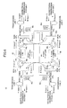
- the input optical signals comprise signals A-band and B-band of different wavelength bands. These optical signals are supplied to a transmission device 30 shown in FIG.4.
- the transmission device 30 comprises wavelength division multiplexing (WDM) devices X 32 1 , 32 2 , 32 3 and 32 4 , WDM devices Y 34 1 , 34 2 , 34 3 and 34 4 , an A-band common unit 36, a B-band common unit 38, and photodiodes 40 1 , 40 2 , 40 3 and 40 4 used for monitoring an OTDR (Optical Time Domain Reflectmeter) signal.
- WDM wavelength division multiplexing
- X 32 1 , 32 2 , 32 3 and 32 4 WDM devices Y 34 1 , 34 2 , 34 3 and 34 4
- an A-band common unit 36 a B-band common unit 38
- photodiodes 40 1 , 40 2 , 40 3 and 40 4 used for monitoring an OTDR (Optical Time Domain Reflectmeter) signal.
- OTDR Optical Time Domain Reflectmeter
- CPL in FIG.4 represents an optical coupler.
- embodiments to be described hereinafter also set forth A-band common units and B-band common units which include optical amplifiers.
- An erbium-doped optical fiber amplifier and a lumped-constant Raman optical amplifier may be used as the optical amplifiers.
- the multiplex wave signal A-band 1 supplied to the transmission device 30 is transmitted through the WDM device X 32 1 and the WDM device Y 34 1 , and is amplified by the A-band common unit 36. Then, the multiplex wave signal A-band 1 is transmitted through the WDM device Y 34 2 and the WDM device X 32 2 , and is output from the transmission device 30.
- the multiplex wave signal B-band 1 supplied to the transmission device 30 is transmitted from the WDM device X 32 2 provided in the transmission system 1 to the WDM device Y 34 4 provided in the transmission system 2.
- the multiplex wave signal B-band 1 is amplified by the B-band common unit 38, and is transmitted from the WDM device Y 34 3 provided in the transmission system 2 to the WDM device X 32 1 provided in the transmission system 1, and is output from the transmission device 30.
- the multiplex wave signal B-band 2 supplied to the transmission device 30 is transmitted through the WDM device X 32 4 and the WDM device Y 34 3 , and is amplified by the B-band common unit 38.
- the multiplex wave signal B-band 2 is transmitted through the WDM device Y 34 4 and the WDM device X 32 3 , and is output from the transmission device 30.
- the multiplex wave signal A-band 2 supplied to the transmission device 30 is transmitted from the WDM device X 32 3 provided in the transmission system 2 to the WDM device Y 34 2 provided in the transmission system 1. Then, the multiplex wave signal A-band 2 is amplified by the A-band common unit 36, and is transmitted from the WDM device Y 34 1 provided in the transmission system 1 to the WDM device X 32 4 provided in the transmission system 2, and is output from the transmission device 30.
- the multiplex wave signals A-band and B-band divided by the respective WDM devices X are transmitted via the respective WDM devices Y into the A-band common unit 36 and the B-band common unit 38, respectively, in the opposite directions. Accordingly, two multiplex wave signals derived from two different transmission systems are amplified by one common (optical amplifier) unit. Therefore, one optical amplifier suffices for each of wavelength bands.
- the signals A-band and B-band supplied to the transmission system 1 and 2 are propagated in opposite directions through the respective transmission lines.
- This arrangement can inhibit an occurrence of a nonlinear effect, and can also reduce Raman crosstalk between the signals.
- the multiplex wave signals A-band 1 and A-band 2, and the multiplex wave signals B-band 1 and B-band 2 are arranged alternately in terms of wavelength bands.
- the axis of abscissas indicates wavelength bands
- the axis of ordinates indicates optical intensities, as in FIG.3.
- Wavelength bands (channels) of A-band 2 and B-band 2 shown in the lower graph are alternated with wavelength bands (channels) of the multiplex wave signals A-band 1 and B-band 1 shown in the upper graph, respectively. This arrangement reduces an ASE power, compared to a simple unidirectional optical amplification.
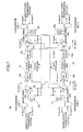
- a transmission device 42 according to the present second embodiment comprises WDM couplers 46 1 , 46 2 , 46 3 and 46 4 in place of the WDM devices X, and optical circulators 48 1 , 48 2 , 48 3 and 48 4 in place of the WDM devices Y.
- optical signal transmittances are the same as in the first embodiment.
- the arrangement according to the present second embodiment can inhibit an occurrence of a nonlinear effect, and can also reduce Raman crosstalk between the signals, as in the first embodiment.
- the optical circulator performs an isolation of a reflected light which is conventionally performed by an optical isolator.
- the optical circulator not only divides the signals A-band and B-band, but also performs the isolation.
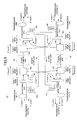
- a transmission device 50 according to the present third embodiment comprises optical circulators 52 1 , 52 2 , 52 3 and 52 4 in place of the WDM devices X, and interleavers 54 1 , 54 2 , 54 3 and 54 4 in place of the WDM devices Y.
- optical signal transmittances are the same as in the first embodiment.
- the arrangement according to the present third embodiment can inhibit an occurrence of a nonlinear effect, and can also reduce Raman crosstalk between the signals, as in the first embodiment.
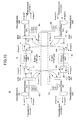
- a transmission device 56 according to the present fourth embodiment comprises the WDM couplers 46 1 , 46 2 , 46 3 and 46 4 in place of the WDM devices X, and the interleavers 54 1 , 54 2 , 54 3 and 54 4 in place of the WDM devices Y.
- optical signal transmittances are the same as in the first embodiment.
- the arrangement according to the present fourth embodiment can inhibit an occurrence of a nonlinear effect, and can also reduce Raman crosstalk between the signals, as in the first embodiment.
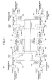
- FIG.9 is a diagram of a transmission device 58 according to the present fifth embodiment.
- Input optical signals are the multiplex wave signals A-band and B-band of different wavelength bands, as in the above-described first to fourth embodiments. These optical signals are supplied to the transmission device 58.
- the transmission device 58 comprises the wavelength division multiplexing (WDM) devices X 32 1 , 32 2 , 32 3 and 32 4 , the WDM devices Y 34 1 , 34 2 , 34 3 and 34 4 , the A-band common unit 36, the B-band common unit 38, and the photodiodes 40 1 , 40 2 , 40 3 and 40 4 .
- WDM wavelength division multiplexing
- the multiplex wave signals A-band 1 and B-band 1 are propagated thorough the transmission system 1
- the multiplex wave signals A-band 2 and B-band 2 are propagated thorough the transmission system 2.
- Each pair of the multiplex wave signals A-band and B-band are propagated in an identical direction through the respective transmission lines thereof.
- the multiplex wave signal A-band 1 and the multiplex wave signal B-band 1 supplied to the transmission device 58 are divided by the WDM device X 32 1 .
- the multiplex wave signal A-band 1 is transmitted through the WDM device Y 34 1 , and is amplified by the A-band common unit 36.
- the multiplex wave signal A-band 1 is transmitted through the WDM device Y 34 2 , and is multiplexed with the amplified multiplex wave signal B-band 1 by the WDM device X 32 2 so as to be output from the transmission device 58.
- the multiplex wave signal B-band 1 divided from the multiplex wave signal A-band 1 by the WDM device X 32 1 is transmitted through the WDM device Y 34 3 provided in the transmission system 2, and is amplified by the B-band common unit 38. Then, the multiplex wave signal B-band 1 is transmitted from the WDM device Y 34 4 provided in the transmission system 2 to the WDM device X 32 2 provided in the transmission system 1, and is multiplexed with the amplified multiplex wave signal A-band 1 by the WDM device X 32 2 so as to be output from the transmission device 58.
- the multiplex wave signal A-band 2 and the multiplex wave signal B-band 2 supplied to the transmission device 58 are divided by the WDM device X 32 3 .
- the multiplex wave signal B-band 2 is transmitted through the WDM device Y 34 4 , and is amplified by the B-band common unit 38.
- the multiplex wave signal B-band 1 is transmitted through the WDM device Y 34 3 , and is multiplexed with the amplified multiplex wave signal A-band 2 by the WDM device X 32 4 so as to be output from the transmission device 58.
- the multiplex wave signal A-band 2 divided from the multiplex wave signal B-band 2 by the WDM device X 32 3 is transmitted through the WDM device Y 34 2 provided in the transmission system 1, and is amplified by the A-band common unit 36. Then, the multiplex wave signal A-band 2 is transmitted from the WDM device Y 34 1 provided in the transmission system 1 to the WDM device X 32 4 provided in the transmission system 2, and is multiplexed with the amplified multiplex wave signal B-band 2 by the WDM device X 32 4 so as to be output from the transmission device 58.
- the signals A-band or B-band supplied to the transmission system 1 and 2 are propagated in opposite directions, as in the first embodiment, when transmitted through the A-band common unit 36 or the B-band common unit 38.
- This arrangement can inhibit an occurrence of a nonlinear effect, and can also reduce Raman crosstalk between the signals.
- the WDM devices are used so that the signals A-band or B-band supplied to the transmission system 1 and 2 can be propagated in opposite directions through the respective transmission lines.
- a transmission device 60 according to the present sixth embodiment comprises WDM couplers 62 1 , 62 2 , 62 3 and 62 4 in place of the WDM devices X, and circulators 64 1 , 64 2 , 64 3 and 64 4 in place of the WDM devices Y.
- optical signal transmittances are the same as in the fifth embodiment.
- the arrangement according to the present sixth embodiment can inhibit an occurrence of a nonlinear effect, and can also reduce Raman crosstalk between the signals, as in the fifth embodiment.
- a transmission device 65 according to the present seventh embodiment comprises the WDM couplers 62 1 , 62 2 , 62 3 and 62 4 in place of the WDM devices X, and interleavers 66 1 , 66 2 , 66 3 and 66 4 in place of the WDM devices Y.
- optical signal transmittances are the same as in the fifth embodiment.
- the arrangement according to the present seventh embodiment can inhibit an occurrence of a nonlinear effect, and can also reduce Raman crosstalk between the signals, as in the fifth embodiment.
- the transmission devices of the above-described first to fourth embodiments are interconnected by optical fibers as shown in FIG.12.
- the transmission devices are connected with positive dispersion fibers that are interconnected by a negative dispersion fiber.
- This dispersion management transmission line can suppress an occurrence of a nonlinear effect.
- the transmission devices are interconnected as shown in FIG.13.
- a positive dispersion fiber is connected to an output end of each transmission device, and a negative dispersion fiber is connected to an input end of each transmission device so as to suppress an occurrence of a nonlinear effect.
- FIG.14 is a diagram of a transmission device in which optical couplers used for distributed Raman amplifications, and pump (excitation) laser diodes 41 1 and 41 2 are provided on the above-mentioned dispersion management transmission line.
- an excitation light is supplied via these elements to Raman amplification media.
- an optical signal can be amplified by distributed Raman amplifications in a transmission line.
- An optical coupler is provided between photodiodes so as to monitor an input optical level.
- an optical coupler is provided between the photodiodes 40 2 and 40 4 .
- an optical coupler CPL-A and an optical coupler CPL-B are provided so that input optical levels can be monitored by using monitoring photodiodes (monitoring units) 68 1 , 68 2 , 68 3 and 68 4 in respective directions.
- FIG.16 is an example of modularization of the optical transmission device shown in FIG.6. Elements in FIG.16 that are identical or equivalent to the elements shown in FIG.6 are referenced by the same reference marks.
- optical modules 70 1 and 70 2 are enclosed by dotted lines.
- the optical module 70 1 comprises the WDM couplers 46 1 and 46 4 , and the optical circulators 48 1 and 48 3 .
- the optical module 70 2 comprises the WDM couplers 46 2 and 46 3 , and the optical circulators 48 2 and 48 4 .
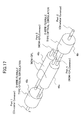
- FIG.17 is a perspective view of the optical module 70 2 .
- a port 1 of the optical circulator 48 2 is connected to the A-band optical amplifier 72 1 .
- a port 2 of the optical circulator 48 4 is connected to the B-band optical amplifier 72 2 .
- a port 3 and a port 4 of the WDM couplers 46 2 and 46 3 are optical fibers for inputting and outputting optical signals to and from the transmission device.
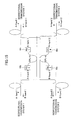
- FIG.18 is an example of modularization of the optical transmission device shown in FIG.7. Elements in FIG.18 that are identical or equivalent to the elements shown in FIG.7 are referenced by the same reference marks.
- optical modules 74 1 and 74 2 are enclosed by dotted lines.
- the optical module 74 1 comprises the optical circulators 52 1 and 52 4 , and the interleavers 54 1 and 54 3 .
- the optical modules 74 2 comprises the optical circulators 52 2 and 52 3 , and the interleavers 54 2 and 54 4 .
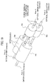
- FIG.19 is a perspective view of the optical module 74 2 .
- a port 4 of the interleaver 54 4 is connected to the B-band optical amplifier 76 2 .
- a port 3 of the interleaver 54 2 is connected to the A-band optical amplifier 76 1 .
- a port 1 and a port 2 of the optical circulators 52 2 and 52 3 are optical fibers for inputting and outputting optical signals to and from the transmission device.
- modularizing the optical device can decrease the number of components.
- FIG.20 and FIG.21 illustrate examples where an excitation light is supplied from either forward or backward of an optical amplification medium 79.
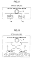
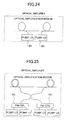
- FIG.22 and FIG.23 illustrate examples where excitation lights are supplied from both forward and backward of the optical amplification medium 79.
- a pump laser diode (LD) 78 1 squared by a broken line, but a pump laser diode (LD) 78 2 squared by a solid line supplies an excitation light.
- LD pump laser diode
- an excitation light is supplied to the optical amplification medium 79, not from a PM-CPL (a polarized-wave coupler) 82 1 as indicated by a broken line extended therefrom, but from a PM-CPL 82 2 as indicated by a solid line extended therefrom.
- PM-CPL a polarized-wave coupler
- Each of the PM-CPL 82 1 and the PM-CPL 82 2 orthogonalizes polarized waves of two light sources (pump LDs) so as to double the light sources and eliminate a polarization dependency.
- both pump laser diodes (LDs) 84 1 and 84 2 squared by solid lines supply excitation lights.
- excitation lights are supplied to the optical amplification medium 79 from both PM-CPLs 88 1 and 88 2 as indicated by solid lines extended therefrom.
- optical fibers optical amplification mediums
- both pump laser diodes (LDs) 90 1 and 90 2 supply excitation lights to the optical fibers from inside therebetween.
- excitation lights are supplied from both PM-CPLs 92 1 and 92 2 to the optical fibers from inside therebetween. Exciting the optical fibers from both forward and backward thereof may cause the excitation lights to leak such that PM-CPLs exert adverse effects on each other. To reduce these adverse effects, the PM-CPLs 92 1 and 92 2 excite the optical fibers outwardly from inside therebetween.
- FIG.26 shows an optical amplifier comprising gain equalizers 94 1 and 94 2 provided at a preceding stage and a subsequent stage of an optical amplification medium.
- the gain equalizer 94 1 squared by a broken line, but the gain equalizer 94 2 squared by a solid line equalizes a gain. Either of the gain equalizers 94 1 and 94 2 is used depending on a direction in which optical signals are supplied.
- FIG.27 shows an optical amplifier comprising gain equalizers 96 1 and 96 2 symmetrically so as to balance a gain equalization by using both the gain equalizers 96 1 and 96 2 .
- These gain equalizers 96 1 and 96 2 have different loss wavelengths, and both the gain equalizers 96 1 and 96 2 together equalize a gain wavelength characteristic of the optical amplifier by using a synthesized characteristic of both the gain equalizers 96 1 and 96 2 .
- FIG.28 shows an optical amplifier comprising a gain equalizer 98 placed between two optical amplification mediums. This gain equalizer 98 has a loss wavelength characteristic similar to a gain wavelength characteristic obtained by the two optical amplification mediums.
- a long-period fiber grating filter, a slant-type fiber grating filter, a filter using a Faraday rotator, etc. may be used as these gain equalizers.
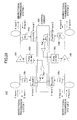
- FIG.29 is a diagram of an optical repeating amplifier 110 having a function of controlling excitation lights.
- This optical repeating amplifier 110 comprises an A-band optical amplification medium 104 (corresponding to the A-band common unit 36), a B-band optical amplification medium 106 (corresponding to the B-band common unit 38), four photodiodes (PDs) 100 1 , 100 2 , 100 3 and 100 4 , a control circuit 108, and two pump (excitation) laser diodes (LDs) 102 1 and 102 2 supplying excitation lights to the A-band optical amplification medium 104 and the B-band optical amplification medium 106, respectively.
- PDs photodiodes
- LDs pump (excitation) laser diodes
- the control circuit 108 controls a drive current driving the pump laser diode 102 1 such that a power level of an optical output of A-band 1 monitored by the photodiode 100 2 and a power level of an optical output of A-band 2 monitored by the photodiode 100 3 make a constant sum.
- the control circuit 108 controls a drive current driving the pump laser diode 102 2 such that a power level of an optical output of B-band 1 monitored by the photodiode 100 1 and a power level of an optical output of B-band 2 monitored by the photodiode 100 4 make a constant sum.
- the optical repeating amplifier 110 receives a monitor command by photoelectrically converting a monitor command optical signal of A-band, which is modulated at a predetermined frequency by another transmitter, by the photodiode 100 2 or 100 3 , and thereafter extracting the monitor command optical signal by an electric band pass filter.
- the monitor command signal may be superimposed on the multiple-wavelength signal A-band.
- the monitor command signal may have wavelengths different from the multiple-wavelength signal A-band such that the optical repeating amplifier 110 receives the monitor command signal by using an optical band pass filter extracting the wavelengths.
- the above-described monitor-command signal receiving methods are also applicable to the multiple-wavelength signal B-band.
- the monitor command optical signal of B-band is photoelectrically converted by the photodiode 100 1 or 100 4 .
- the above-mentioned drive current driving the pump laser diode may be superimposed subordinately on a monitor response signal having a frequency different from the frequency of the monitor command signal such that the optical repeating amplifier transfers the monitor response signal to another receiver.
- a long-period fiber grating filter, a slant-type fiber grating filter, and a filter using a Faraday rotator may be used as the filters in this arrangement.
- These three filters have loss wavelength characteristics equal in forward and reverse directions, and exhibit such a large return loss as to dispense with other optical components for eliminating reflected lights. Therefore, using the above-mentioned three filters can reduce a number of components in the optical repeating amplifier.
- the optical amplifier modulates the excitation light sources.
- the gain equalizer does not have excitation light sources. Therefore, employing the filter using a Faraday rotator involves a utilization of a characteristic enabling a variable modulating by varying a current flowing in an electromagnet of the Faraday rotator.
- FIG.30 is a diagram of a transmission device to which an input signal including three wavelength bands is supplied.
- a multiple-wavelength signal including three wavelength bands A-band, B-band and C-band is divided into three signals A-band, B-band and C-band by a WDM device X 112 1 .
- the signal A-band is transmitted through a WDM device Y 114 1 , and is amplified by an A-band common unit 116.
- the signal A-band is transmitted through a WDM device Y 114 4 , and is multiplexed by a WDM device X 1122 so as to be output from the transmission device.
- the signal B-band is transmitted through a WDM device Y 114 2 , and is amplified by a B-band common unit 118.
- the signal B-band is transmitted through a WDM device Y 114 5 , and is multiplexed by the WDM device X 112 2 so as to be output from the transmission device.
- the signal C-band is transmitted through a WDM device Y 114 3 , and is amplified by a C-band common unit 120.
- the signal C-band is transmitted through a WDM device Y 114 6 , and is multiplexed by the WDM device X 112 2 so as to be output from the transmission device.
- a multiple-wavelength signal supplied in an opposite direction to a WDM device X 112 3 is processed in a converse manner so as to be output from a WDM device X 112 4 .
- the transmission devices according to the present embodiment can process multiple-wavelength signals including more than two wavelength bands.
- the multiple-wavelength signals A-band and B-band correspond to multiple-wavelength signals (multiplex optical signals) of two different wavelength bands.
- the A-band common unit and the B-band common unit correspond to a first optical amplifier amplifying a signal of a first wavelength band and a second optical amplifier amplifying a signal of a second wavelength band, respectively.
- the elements replacing the A-band common unit and the B-band common unit also correspond to the first optical amplifier and the second optical amplifier.
- the WDM devices X and the WDM devices Y correspond to a wavelength division multiplexing unit as dividing means or multiplexing means.
Landscapes
- Physics & Mathematics (AREA)
- Electromagnetism (AREA)
- Engineering & Computer Science (AREA)
- Computer Networks & Wireless Communication (AREA)
- Signal Processing (AREA)
- Optical Communication System (AREA)
- Optical Modulation, Optical Deflection, Nonlinear Optics, Optical Demodulation, Optical Logic Elements (AREA)
- Lasers (AREA)
Abstract
Description
the multiplex optical signal of the second wavelength band propagated through the first transmission line and the multiplex optical signal of the second wavelength band propagated through the second transmission line may be supplied into the second optical amplifier in opposite directions.
the multiplex optical signal of the first wavelength band transmitted through the first transmission line and the multiplex optical signal of the first wavelength band transmitted through the second transmission line may be supplied into the first optical amplifier in opposite directions, and
the multiplex optical signal of the second wavelength band transmitted through the first transmission line and the multiplex optical signal of the second wavelength band transmitted through the second transmission line may be supplied into the second optical amplifier in opposite directions.
Claims (12)
- A transmission device (30; 58) housing a plurality of transmission lines (1, 2) each propagating multiplex optical signals of a plurality of wavelength bands (A-band, B-band),
characterized by comprising:an optical amplifier (36, 38) used commonly for each of said wavelength bands (A-band, B-band), the optical amplifier (36, 38) being provided commonly for all of said transmission lines (1, 2). - The transmission device (30; 58) as claimed in claim 1, characterized by further comprising a wavelength division multiplexing unit (32, 34) dividing said multiplex optical signals propagated through each of said transmission lines (1, 2) according to said wavelength bands (A-band, B-band) so as to supply each of said multiplex optical signals to said optical amplifier (36, 38), and multiplexing each of said multiplex optical signals amplified by said optical amplifier (36, 38) so as to output said multiplex optical signals.
- A transmission device (30; 58) housing a first transmission line (1) and a second transmission line (2) each propagating a multiplex optical signal of a first wavelength band (A-band) and a multiplex optical signal of a second wavelength band (B-band),
characterized by comprising:a first optical amplifier (36) provided commonly for said first transmission line (1) and said second transmission line (2) so as to amplify said multiplex optical signal of said first wavelength band (A-band) propagated through each of said first transmission line (1) and said second transmission line (2); anda second optical amplifier (38) provided commonly for said first transmission line (1) and said second transmission line (2) so as to amplify said multiplex optical signal of said second wavelength band (B-band) propagated through each of said first transmission line (1) and said second transmission line (2). - The transmission device (30; 58) as claimed in claim 3, characterized by further comprising a wavelength division multiplexing unit (32, 34) dividing said multiplex optical signal of said first wavelength band (A-band) and said multiplex optical signal of said second wavelength band (B-band) propagated through each of said first transmission line (1) and said second transmission line (2) so as to supply said multiplex optical signal of said first wavelength band (A-band) and said multiplex optical signal of said second wavelength band (B-band) to said first optical amplifier (36) and said second optical amplifier (38), respectively, and multiplexing said multiplex optical signal of said first wavelength band (A-band) and said multiplex optical signal of said second wavelength band (B-band) amplified by said first optical amplifier (36) and said second optical amplifier (38), respectively, so as to output said multiplex optical signal of said first wavelength band (A-band) and said multiplex optical signal of said second wavelength band (B-band).
- The transmission device (30) as claimed in claim 3 or 4, characterized in that:said multiplex optical signal of said first wavelength band (A-band) propagated through said first transmission line (1) and said multiplex optical signal of said first wavelength band (A-band) propagated through said second transmission line (2) are supplied into said first optical amplifier (36) in opposite directions; andsaid multiplex optical signal of said second wavelength band (B-band) propagated through said first transmission line (1) and said multiplex optical signal of said second wavelength band (B-band) propagated through said second transmission line (2) are supplied into said second optical amplifier (38) in opposite directions.
- The transmission device (58) as claimed in claim 3 or 4, characterized in that:said multiplex optical signal of said first wavelength band (A-band) and said multiplex optical signal of said second wavelength band (B-band) are transmitted to the transmission device (58) in an identical direction through each of said first transmission line (1) and said second transmission line (2);said multiplex optical signal of said first wavelength band (A-band) transmitted through said first transmission line (1) and said multiplex optical signal of said first wavelength band (A-band) transmitted through said second transmission line (2) are supplied into said first optical amplifier (36) in opposite directions; andsaid multiplex optical signal of said second wavelength band (B-band) transmitted through said first transmission line (1) and said multiplex optical signal of said second wavelength band (B-band) transmitted through said second transmission line (2) are supplied into said second optical amplifier (38) in opposite directions.
- The transmission device (30; 58) as claimed in one of claims 3 to 6, characterized in that said first wavelength band (A-band) in said first transmission line (1) and said second transmission line (2) includes channels of different wavelengths (A-band 1, A-band 2), and said second wavelength band (B-band) in said first transmission line (1) and said second transmission line (2) includes channels of different wavelengths (B-band 1, B-band 2).
- The transmission device (30; 58) as claimed in claim 4, characterized by further comprising:an optical coupler (CPL-A, CPL-B) provided on each of transmission lines transmitting one of said multiplex optical signal of said first wavelength band (A-band) and said multiplex optical signal of said second wavelength band (B-band) divided by said wavelength division multiplexing unit (32, 34); anda monitoring unit (681, 682, 683 and 684) monitoring the one of said multiplex optical signal of said first wavelength band (A-band) and said multiplex optical signal of said second wavelength band (B-band) branched by said optical coupler (CPL-A, CPL-B).
- The transmission device (30; 58) as claimed in claim 4, characterized by further comprising gain equalizers (941, 942; 961, 962) provided at a preceding stage and a subsequent stage of each of said first optical amplifier (36) and said second optical amplifier (38).
- The transmission device (30; 58) as claimed in claim 4, characterized in that each of said first optical amplifier (36) and said second optical amplifier (38) comprises two optical amplification mediums, and a gain equalizer (98) placed therebetween.
- The transmission device (30; 58) as claimed in claim 4, characterized in that each of said first optical amplifier (36) and said second optical amplifier (38) comprises two optical amplification mediums supplied with excitation lights from inside between said two optical amplification mediums.
- The transmission device (30; 58) as claimed in claim 4, characterized in that a drive current driving an excitation laser diode (1021, 1022) supplying an excitation light to each of said first optical amplifier (36; 104) and said second optical amplifier (38; 106) is controlled such that optical output power levels of output multiplex optical signals of either of said first wavelength band (A-band) and said second wavelength band (B-band) make a constant sum.
Applications Claiming Priority (2)
| Application Number | Priority Date | Filing Date | Title |
|---|---|---|---|
| JP2001329085 | 2001-10-26 | ||
| JP2001329085A JP2003134089A (en) | 2001-10-26 | 2001-10-26 | Transmission equipment |
Publications (2)
| Publication Number | Publication Date |
|---|---|
| EP1306988A2 true EP1306988A2 (en) | 2003-05-02 |
| EP1306988A3 EP1306988A3 (en) | 2004-02-11 |
Family
ID=19145043
Family Applications (1)
| Application Number | Title | Priority Date | Filing Date |
|---|---|---|---|
| EP02007322A Withdrawn EP1306988A3 (en) | 2001-10-26 | 2002-04-04 | Wavelength/band-specific optical amplifier |
Country Status (3)
| Country | Link |
|---|---|
| US (1) | US20030081285A1 (en) |
| EP (1) | EP1306988A3 (en) |
| JP (1) | JP2003134089A (en) |
Cited By (1)
| Publication number | Priority date | Publication date | Assignee | Title |
|---|---|---|---|---|
| EP3614581A4 (en) * | 2017-04-18 | 2020-05-06 | Nec Corporation | Bidirectional optical transmission system and bidirectional optical transmission method |
Families Citing this family (10)
| Publication number | Priority date | Publication date | Assignee | Title |
|---|---|---|---|---|
| WO2009093425A1 (en) * | 2008-01-21 | 2009-07-30 | Nikon Corporation | Wide-band optical amplifier, optical pulse generator, and optical instrument |
| JP2010206701A (en) * | 2009-03-05 | 2010-09-16 | Sumitomo Electric Ind Ltd | Optical transmission system |
| US9197352B2 (en) * | 2013-03-11 | 2015-11-24 | Google Inc. | Increasing the capacity of a WDM-PON with wavelength reuse |
| JP5659341B2 (en) * | 2013-06-05 | 2015-01-28 | 日本電信電話株式会社 | Multi-core optical transmission system, optical amplification and optical amplification components |
| JP6711448B2 (en) * | 2017-02-22 | 2020-06-17 | 日本電気株式会社 | Optical repeater system |
| WO2018210470A1 (en) * | 2017-05-17 | 2018-11-22 | Alcatel Lucent | Use of band-pass filters in supervisory signal paths of an optical transport system |
| JP7136183B2 (en) * | 2018-03-02 | 2022-09-13 | 日本電気株式会社 | Optical Repeater, Transmission Line Fiber Monitoring Method, and Optical Transmission System |
| JP2019220775A (en) | 2018-06-18 | 2019-12-26 | 日本電信電話株式会社 | Optical amplifier, optical transmission system, and optical cable failure place measuring method |
| EP4027536A4 (en) * | 2019-09-02 | 2022-11-02 | KDDI Corporation | COMMUNICATION DEVICE AND COMMUNICATION SYSTEM |
| WO2025062579A1 (en) * | 2023-09-21 | 2025-03-27 | 日本電信電話株式会社 | Core switching device and optical amplification system |
Family Cites Families (7)
| Publication number | Priority date | Publication date | Assignee | Title |
|---|---|---|---|---|
| US5926590A (en) * | 1995-12-29 | 1999-07-20 | Mci Communications Corporation | Power equalizer in a multiple wavelength bidirectional lightwave amplifier |
| US5812306A (en) * | 1996-06-14 | 1998-09-22 | Ciena Corporation | Bidirectional WDM optical communication systems with bidirectional optical amplifiers |
| US5912749A (en) * | 1997-02-11 | 1999-06-15 | Lucent Technologies Inc. | Call admission control in cellular networks |
| JP4031853B2 (en) * | 1997-10-20 | 2008-01-09 | 富士通株式会社 | Optical transmission equipment for bidirectional optical communication |
| JP2001203644A (en) * | 2000-01-18 | 2001-07-27 | Fujitsu Ltd | Optical amplifier and optical amplification method |
| US6310716B1 (en) * | 2000-08-18 | 2001-10-30 | Corning Incorporated | Amplifier system with a discrete Raman fiber amplifier module |
| US6490386B1 (en) * | 2001-01-31 | 2002-12-03 | Xiaofan Cao | Bidirectional optical amplifier |
-
2001
- 2001-10-26 JP JP2001329085A patent/JP2003134089A/en not_active Withdrawn
-
2002
- 2002-03-25 US US10/103,962 patent/US20030081285A1/en not_active Abandoned
- 2002-04-04 EP EP02007322A patent/EP1306988A3/en not_active Withdrawn
Cited By (1)
| Publication number | Priority date | Publication date | Assignee | Title |
|---|---|---|---|---|
| EP3614581A4 (en) * | 2017-04-18 | 2020-05-06 | Nec Corporation | Bidirectional optical transmission system and bidirectional optical transmission method |
Also Published As
| Publication number | Publication date |
|---|---|
| US20030081285A1 (en) | 2003-05-01 |
| EP1306988A3 (en) | 2004-02-11 |
| JP2003134089A (en) | 2003-05-09 |
Similar Documents
| Publication | Publication Date | Title |
|---|---|---|
| US20240421908A1 (en) | Pluggable optical amplifier for datacenter interconnects | |
| JP4671478B2 (en) | Wavelength multiplexing optical communication system and wavelength multiplexing optical communication method | |
| US6882466B1 (en) | Optical amplifier | |
| KR100378111B1 (en) | Optical amplifier and bidirectional wavelength division multiplexing optical communication system using that | |
| US5831754A (en) | Optical amplifier | |
| US6104848A (en) | WDM optical transmitter | |
| EP1130803A2 (en) | Method and apparatus for measuring optical signal-to-noise ratio, and pre-emphasis method, in an optical communication system | |
| US20030206692A1 (en) | Optical transmission system and optical coupler/branching filter | |
| EP1306988A2 (en) | Wavelength/band-specific optical amplifier | |
| US6823107B2 (en) | Method and device for optical amplification | |
| US6147796A (en) | Method for determining transmission parameters for the data channels of a WDM optical communication system | |
| US20180212702A1 (en) | Amplification device with amplification stages with polarized soas and processing stage, for amplifying optical signals in a wdm transmission system | |
| JPH08335913A (en) | Optical amplification monitoring device | |
| JP2001024594A (en) | Optical amplifier and system having the optical amplifier | |
| JP2001203644A (en) | Optical amplifier and optical amplification method | |
| US20230163555A1 (en) | Optical amplifier modules | |
| JP3232625B2 (en) | Optical repeater and monitoring information transfer method | |
| JP2002232362A (en) | Optical repeater transmission system and optical repeater transmission method | |
| US8189258B2 (en) | Optical amplifier configuration | |
| US20050036790A1 (en) | Method and system for optical fiber transmission using Raman amplification | |
| US20220337018A1 (en) | Parallel o-band amplifier | |
| US6907157B2 (en) | Method and system for optical fiber transmission using raman amplification | |
| US20260074481A1 (en) | Optical amplifier and related device | |
| WO2005124446A1 (en) | Optical amplifier and optical communication system | |
| JP3503600B2 (en) | Optical transmitting device and optical receiving device |
Legal Events
| Date | Code | Title | Description |
|---|---|---|---|
| PUAI | Public reference made under article 153(3) epc to a published international application that has entered the european phase |
Free format text: ORIGINAL CODE: 0009012 |
|
| AK | Designated contracting states |
Designated state(s): AT BE CH CY DE DK ES FI FR GB GR IE IT LI LU MC NL PT SE TR |
|
| AX | Request for extension of the european patent |
Extension state: AL LT LV MK RO SI |
|
| PUAL | Search report despatched |
Free format text: ORIGINAL CODE: 0009013 |
|
| AK | Designated contracting states |
Kind code of ref document: A3 Designated state(s): AT BE CH CY DE DK ES FI FR GB GR IE IT LI LU MC NL PT SE TR |
|
| AX | Request for extension of the european patent |
Extension state: AL LT LV MK RO SI |
|
| STAA | Information on the status of an ep patent application or granted ep patent |
Free format text: STATUS: THE APPLICATION HAS BEEN WITHDRAWN |
|
| 18W | Application withdrawn |
Effective date: 20040323 |