EP1306957A1 - Charging/discharging apparatus and method, power supplying apparatus and method, power supplying system and method, program storage medium, and program - Google Patents
Charging/discharging apparatus and method, power supplying apparatus and method, power supplying system and method, program storage medium, and program Download PDFInfo
- Publication number
- EP1306957A1 EP1306957A1 EP02700570A EP02700570A EP1306957A1 EP 1306957 A1 EP1306957 A1 EP 1306957A1 EP 02700570 A EP02700570 A EP 02700570A EP 02700570 A EP02700570 A EP 02700570A EP 1306957 A1 EP1306957 A1 EP 1306957A1
- Authority
- EP
- European Patent Office
- Prior art keywords
- charging
- charging capacity
- controlling
- capacity
- voltage value
- Prior art date
- Legal status (The legal status is an assumption and is not a legal conclusion. Google has not performed a legal analysis and makes no representation as to the accuracy of the status listed.)
- Withdrawn
Links
Images







Classifications
-
- H—ELECTRICITY
- H02—GENERATION; CONVERSION OR DISTRIBUTION OF ELECTRIC POWER
- H02J—ELECTRIC POWER NETWORKS; CIRCUIT ARRANGEMENTS OR SYSTEMS FOR SUPPLYING OR DISTRIBUTING ELECTRIC POWER; SYSTEMS FOR STORING ELECTRIC ENERGY
- H02J7/00—Circuit arrangements for charging or discharging batteries or for supplying loads from batteries
- H02J7/50—Circuit arrangements for charging or discharging batteries or for supplying loads from batteries acting upon multiple batteries simultaneously or sequentially
-
- H—ELECTRICITY
- H02—GENERATION; CONVERSION OR DISTRIBUTION OF ELECTRIC POWER
- H02J—ELECTRIC POWER NETWORKS; CIRCUIT ARRANGEMENTS OR SYSTEMS FOR SUPPLYING OR DISTRIBUTING ELECTRIC POWER; SYSTEMS FOR STORING ELECTRIC ENERGY
- H02J7/00—Circuit arrangements for charging or discharging batteries or for supplying loads from batteries
-
- H—ELECTRICITY
- H02—GENERATION; CONVERSION OR DISTRIBUTION OF ELECTRIC POWER
- H02J—ELECTRIC POWER NETWORKS; CIRCUIT ARRANGEMENTS OR SYSTEMS FOR SUPPLYING OR DISTRIBUTING ELECTRIC POWER; SYSTEMS FOR STORING ELECTRIC ENERGY
- H02J7/00—Circuit arrangements for charging or discharging batteries or for supplying loads from batteries
- H02J7/70—Circuit arrangements for charging or discharging batteries or for supplying loads from batteries characterised by the mechanical construction
- H02J7/751—Circuit arrangements for charging or discharging batteries or for supplying loads from batteries characterised by the mechanical construction concerning the insertion or the connection of the batteries
-
- H—ELECTRICITY
- H02—GENERATION; CONVERSION OR DISTRIBUTION OF ELECTRIC POWER
- H02J—ELECTRIC POWER NETWORKS; CIRCUIT ARRANGEMENTS OR SYSTEMS FOR SUPPLYING OR DISTRIBUTING ELECTRIC POWER; SYSTEMS FOR STORING ELECTRIC ENERGY
- H02J7/00—Circuit arrangements for charging or discharging batteries or for supplying loads from batteries
- H02J7/90—Regulation of charging or discharging current or voltage
- H02J7/933—Regulation of charging or discharging current or voltage the cycle being controlled or terminated in response to electric parameters
-
- H—ELECTRICITY
- H01—ELECTRIC ELEMENTS
- H01M—PROCESSES OR MEANS, e.g. BATTERIES, FOR THE DIRECT CONVERSION OF CHEMICAL ENERGY INTO ELECTRICAL ENERGY
- H01M10/00—Secondary cells; Manufacture thereof
- H01M10/42—Methods or arrangements for servicing or maintenance of secondary cells or secondary half-cells
- H01M10/425—Structural combination with electronic components, e.g. electronic circuits integrated to the outside of the casing
- H01M10/4257—Smart batteries, e.g. electronic circuits inside the housing of the cells or batteries
-
- Y—GENERAL TAGGING OF NEW TECHNOLOGICAL DEVELOPMENTS; GENERAL TAGGING OF CROSS-SECTIONAL TECHNOLOGIES SPANNING OVER SEVERAL SECTIONS OF THE IPC; TECHNICAL SUBJECTS COVERED BY FORMER USPC CROSS-REFERENCE ART COLLECTIONS [XRACs] AND DIGESTS
- Y02—TECHNOLOGIES OR APPLICATIONS FOR MITIGATION OR ADAPTATION AGAINST CLIMATE CHANGE
- Y02E—REDUCTION OF GREENHOUSE GAS [GHG] EMISSIONS, RELATED TO ENERGY GENERATION, TRANSMISSION OR DISTRIBUTION
- Y02E60/00—Enabling technologies; Technologies with a potential or indirect contribution to GHG emissions mitigation
- Y02E60/10—Energy storage using batteries
Definitions
- the present invention relates to a charging/discharging apparatus and method, a power supplying apparatus and method, a power supplying system and method, a program storing medium, and a program; and particularly to a charging/discharging apparatus and method, power supplying apparatus and method, a power supplying system and method, a program storing medium, and a program where the charging capacity of a charging/discharging apparatus can accurately be corrected.
- a so called charging/discharging technique is generally becoming popular in which power is supplied from such a power supplying apparatus as a battery charger to a charging/discharging apparatus represented by a battery pack used in a video camera or the like to charge the same.
- a battery pack of such a type where a microcomputer is incorporated therein and the charging capacity of the battery pack is memorized or stored in the computer has been provided for a practical use.
- the computer causes a built-in RAM (Random Access Memory), an EEPROM (Electrically Erasable Programmable Read Only Memory), a ROM (Read Only Memory) or the like to store data or information on the charging capacity of a battery pack now on use.
- the microcomputer reads out the stored information on the charging capacity to transmit the information to the video camera or the battery charger.
- the operation time or the charging time of the battery pack is calculated on the basis of this information and displayed in the video camera or the battery charger.
- the allowable operation time of a battery pack has a relationship with the charging voltage of the battery pack shown in Fig. 2. That is, in case of the charging capacity of a battery pack which can drive a video camera for 120 minutes at maximum, for example, indication of about 8.4V shows a full charged state (100% charged state), and a time display of 120 minutes is performed as the allowable operation time. Then, the charging voltage and the allowable operation time decreases as an operating time elapses.
- a pre-end voltage Vpre Voltage Pre-end
- Vpre Voltage Pre-end
- the pre-end voltage Vpre is set for warning a user in a state the allowable operation time is still left before the charging voltage reaches an end voltage Ve (Voltage end) (for example, 6.5V: a voltage at which a video camera or the like can not be driven) in order to prompt the user to perform a saving operation safely.
- Ve Voltage end
- the relationship between the charging time and the allowable operation time varies due to self-discharging of the battery pack, for example, as shown in Fig. 3. That is, since the charging voltage is changed to a lowered state (the charging capacity is reduced) due to the self-discharging, which results in reduction in actual allowable operation time. Even in this state, however, since the allowable operation time at a full charged state has been stored in the RAM, there is a problem that, though an actual allowable operation time is 30 minutes or so, the allowable operation time indication displays about 80 minutes, which causes an error. Incidentally, the allowable charging capacity has been actually stored in the RAM, and the allowable operation time is computed in the battery charger or the like on the basis of the allowable charging capacity to be displayed.
- a method for detecting a self-discharge of a battery pack in case that the battery pack is left for a long time without using the same there is a method where the state of a battery pack while it is not operated is monitored by a microcomputer in the battery pack and a self-discharged amount corresponding to the monitored state is reduced from the original charged state so that an error in an allowable operation time display of the battery is corrected.
- a power source for driving the microcomputer in the battery pack uses the power of the battery pack.
- microcomputer sleep a non-operation state in a state that the battery pack is not used (a state that charging and discharging are not conducted).
- the present invention has been made in view of these circumstances, and an object thereof is to perform correction such that an allowable operation time of a battery pack can be displayed accurately.
- a first charging/discharging apparatus of the present invention is characterized by comprising standard charging capacity storing means for storing a standard charging capacity, charging capacity storing means for storing the present charging capacity, charging voltage value measuring means for measuring a charging voltage value, transmitting means for transmitting the information on a standard charging capacity, a charging capacity and a charging voltage value to a power supplying apparatus, receiving means for receiving a command for correcting a charging capacity form the power supplying apparatus, and correcting means for correcting the stored charging capacity based on the received from the receiving means.
- the charging voltage value measuring means measure a charging voltage value when the value of the current of the power supplied from a power supplying apparatus is zero or a sufficiently small value close to zero.
- the charging voltage value is a predetermined voltage value corresponding to a charging capacity close to zero or less and the charging capacity stored by the charging capacity storing means has a predetermined rate of a standard charging capacity or more, it is possible to make the correcting means correct the stored charging capacity to zero or a value corresponding to zero.
- the current value measuring means measure a charging current value or a discharging current value when the power supplied from a power supplying apparatus is equal to zero or a sufficiently small value close to zero.
- the charging current value is equal to or less than a predetermined current value corresponding to a charging capacity close to zero and the charging capacity stored by the charging capacity storing means has a predetermined rate of a standard charging capacity or more, it is possible to make the correcting means correct the stored charging capacity to zero.
- the transmitting means further transmit not only the information on a standard charging capacity, a charging capacity and a charging voltage value but also a charging current value, a discharging current value or temperature data to a power supplying apparatus.
- a first charging/discharging method of the present invention is characterized by including a standard charging capacity storing step of storing a standard charging capacity, a charging capacity storing step of storing the present charging capacity, a charging voltage value measuring step of measuring a charging voltage value, a transmitting step of transmitting the information on a standard charging capacity, a charging capacity and a charging voltage value to a power supplying apparatus, a receiving step of receiving a command for correcting a charging capacity from the power supplying apparatus, and a correcting step of correcting the stored charging capacity based on the command received through the processing in the receiving step.
- a program of a first program storing medium of the present invention is characterized by including a standard charging capacity storage controlling step of controlling storage of a standard charging capacity, a charging capacity storage controlling step of controlling storage of the present charging capacity, a charging voltage value measurement controlling step of controlling measurement of a charging voltage value, a transmission controlling step of controlling transmission of the information on a standard charging capacity, charging capacity, and charging voltage value to a power supplying apparatus, a reception controlling step of controlling reception of a command for correcting a charging capacity, and a correction controlling step of controlling correction of the stored charging capacity.
- a first program of the present invention is characterized by executing a standard charging capacity storage controlling step of controlling storage of a standard charging capacity, a charging capacity storage controlling step of controlling storage of the present charging capacity, a charging voltage value measurement controlling step of controlling measurement of a charging voltage value, a transmission controlling step of controlling transmission of the information on a standard charging capacity, a charging capacity and a charging voltage value to a power supplying apparatus, a reception controlling step of controlling reception of a command for correcting a charging capacity and a correction controlling step of controlling correction of the stored charging capacity.
- a power supplying apparatus of the present invention is characterized by comprising receiving means for receiving the information on the standard charging capacity, the charging capacity and the charging voltage value of a charging/discharging apparatus transmitted from the charging/discharging apparatus and transmitting means for transmitting a command for correcting a charging capacity to zero or a value corresponding to zero to the charging/discharging apparatus when a charging voltage value is equal to or less than a predetermined voltage value corresponding to a charging capacity close to zero and the charging capacity has a predetermined rate of the standard charging capacity or more.
- the receiving means receive not only a standard charging capacity, a charging capacity and a charging voltage value but also a charging current value or a discharging current value transmitted from a charging/discharging apparatus.
- a power supplying method of the present invention is characterized by including a receiving step of receiving the information on the standard charging capacity, the charging capacity and the charging voltage value of a charging/discharging apparatus transmitted from the charging/discharging apparatus and a transmitting step of transmitting a command for correcting a charging capacity to zero or a value corresponding to zero when a charging voltage value is equal to or less than a predetermined voltage value corresponding to a charging capacity close to zero and the charging capacity has a predetermined rate of the standard charging capacity or more.
- a program of a second program storing medium of the present invention is characterized by including a reception controlling step of controlling reception of the information on the standard charging capacity, the charging capacity and the charging voltage value of a charging/discharging apparatus transmitted from the charging/discharging apparatus and a transmission controlling step of controlling transmission of a command for correcting a charging capacity to zero or a value corresponding to zero when the charging capacity has a predetermined rate of the standard charging capacity or more.
- a second program of the present invention is characterized by executing a reception controlling step of controlling reception of the information on the standard charging capacity, the charging capacity and the charging voltage value of a charging/discharging apparatus transmitted from the charging/discharging apparatus and a transmission controlling step of controlling transmission of a command for correcting a charging capacity to zero or a value corresponding to zero when the charging voltage value is equal to or less than a predetermined voltage value corresponding to a charging capacity close to zero and the charging capacity has a predetermine rate of the standard charging capacity.
- a first power supplying system of the present invention is characterized in that a charging/discharging apparatus is provided with standard charging capacity storing means for storing a standard charging capacity, charging capacity storing means for storing the present charging capacity, charging voltage value measuring means for measuring a charging voltage value, first transmitting means for transmitting the information on a standard charging capacity, charging capacity, and charging voltage value to a power supplying apparatus, first receiving means for receiving a command for correcting the charging capacity from the power supplying apparatus, and correcting means for correcting the stored charging capacity in accordance with the command received by the first receiving means; and the power supplying apparatus is provided with second receiving means for receiving the standard charging capacity, charging capacity, and charging voltage value of the charging/discharging apparatus transmitted from the charging/discharging apparatus and second transmitting means for transmitting a command for correcting the charging capacity to zero or a value corresponding to zero when the charging voltage value is equal to or less than a predetermined voltage value corresponding to a charging capacity close to zero and the charging capacity has a predetermined rate of the standard charging
- a power supplying method of a first power supplying system of the present invention is characterized in that a charging/discharging method of a charging/discharging apparatus includes a standard charging capacity storing step of storing a standard charging capacity, a charging capacity storing step of storing the present charging capacity, a charging voltage value measuring step of measuring a charging voltage value, a first transmitting step of transmitting the information on a standard charging capacity, a charging capacity and a charging voltage value to a power supplying apparatus, a first receiving step of receiving a command for correcting the charging capacity from the power supplying apparatus, and a correcting step of correcting the stored charging capacity based on the command received through the processing in the first receiving step; and a power supplying method of the power supplying apparatus includes a second receiving step of receiving the standard charging capacity, the charging capacity and the charging voltage value of the charging/discharging apparatus transmitted from the charging/discharging apparatus and a second transmitting step of transmitting a command for correcting the charging capacity to zero or a value corresponding to zero
- a program of a third program storing medium of the present invention is characterized in that a program for controlling a charging/discharging apparatus includes a standard charging capacity storage controlling step of controlling storage of a standard charging capacity, a charging capacity storage controlling step of controlling storage of the present charging capacity, a charging voltage value measurement controlling step of controlling measurement of a charging voltage value, a fist transmission controlling step of controlling transmission of the information on a standard charging capacity, a charging capacity and a charging voltage value to a power supplying apparatus, a first reception controlling step of controlling reception of a command for correcting the charging capacity from the power supplying apparatus, and a correction controlling step of controlling correction of the stored charging capacity in accordance with the command received through the processing in the first reception controlling step; and a program for controlling the power supplying apparatus includes a second reception controlling step of controlling reception of the information on the standard charging capacity, charging capacity, and charging voltage value of the charging/discharging apparatus transmitted from the charging/discharging apparatus and a second transmission controlling step of controlling transmission of a command for correcting a
- a third program of the present invention is characterized by making a computer for controlling a charging/discharging apparatus execute a standard charging capacity storage controlling step of controlling storage of a standard charging capacity, a charging capacity storage controlling step of controlling storage of the present charging capacity, a charging voltage value measurement controlling step of controlling measurement of a charging voltage value, a first transmission controlling step of controlling transmission of the information on a standard charging capacity, a charging capacity and a charging voltage value to a power supplying apparatus, a first reception controlling step of controlling reception of a command for correcting a charging capacity from the power supplying apparatus, and a correction controlling step of controlling correction of a charging capacity based on the command received through the processing in the first reception controlling step; and a computer for controlling the power supplying apparatus execute a second reception controlling step of controlling reception of the information on the standard charging capacity, the charging capacity and the charging voltage value of the charging/discharging apparatus transmitted from the charging/discharging apparatus and a second transmission controlling step of controlling transmission of a command for correcting a charging capacity to zero or a value
- a standard charging capacity is stored, the present charging capacity is stored, a charging voltage value is measured, the information of the standard charging capacity, the charging capacity and the charging voltage value are transmitted to a power supplying apparatus, and a command for correcting a charging capacity is received from the power supplying apparatus and the stored charging capacity is corrected based on the received command.
- the standard charging capacity, the charging capacity and the charging voltage value of a charging/discharging apparatus transmitted from the charging/discharging apparatus are received and a command for correcting a charging capacity to zero or a value corresponding to zero is transmitted to the charging/discharging apparatus when a charging voltage value is equal to or less than a predetermined voltage value corresponding to a charging capacity close to zero and the charging capacity has a predetermined rate of the standard charging capacity or more.
- a charging/discharging apparatus stores a standard charging capacity and the present charging capacity, measures a charging voltage value, and transmits the information on a standard charging capacity, a charging capacity and a charging voltage value to a power supplying apparatus; and a power supplying apparatus receives a command for correcting a charging capacity, corrects the stored charging capacity based on the received command, receives the information on the standard charging capacity, the charging capacity and the charging voltage value of the charging/discharging apparatus transmitted from the charging/discharging apparatus, and transmits a command for correcting a charging capacity to zero or a value corresponding to zero to the charging/discharging apparatus when the charging voltage value is equal to or less than a predetermined voltage value corresponding to a charging capacity close to zero and the charging capacity has a predetermined rate of the standard charging capacity.
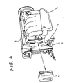
- FIG. 4 is a view showing a configuration of an embodiment of a SQ (Super-quick) battery pack 1 of the present invention.
- the SQ battery pack 1 is set to a battery attaching portion 3 of a video camera 2.
- the SQ battery pack 1 is attached to the battery attaching portion 3 of the video camera 2 to supply power to the video camera 2.
- the SQ battery pack 1 is constituted such that it can be attached to a battery charger 151 to be described later, which is charged by the battery charger 151.
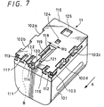
- a conventional battery pack 11 (FIG. 7) can be set to the battery attaching portion 3.
- the charging time of the SQ battery pack 1 is shorter than that of the conventional battery pack 11, because it can be charged at a larger current when it is charged by the battery charger 151.
- a case 101 which stores a battery cell 251a or 251b with reference to FIG. 15, is provided in the pack 1.
- the case 101 of the SQ battery pack 1 is formed by a synthetic resin.
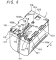
- Guide grooves 102a to 102d (FIG. 6) for guiding the battery attaching portion 3, or slots 162a or 162b of battery charger 151 in the attaching direction shown by the arrow A in FIG. 5 are formed on the width directional both side faces of the case 101. In FIG. 5 , only the guide grooves 102a and 102b are shown.
- the guide grooves 102a to 102d are referred to as the guide 102 when it is not necessary to individually distinguish the guide grooves 102a to 102d. The same is applied to other configurations.
- each guide groove 102 on each side face is formed while one end of the groove 102 is opened on the bottom 115 of the case 101 and formed in the longitudinal direction of the case 101 in parallel.
- Input/output terminals 112 and 113 are formed at the width directional both sides of the case 101 at the front portion 111 shown by the direction of the arrow A in FIG. 6 to the battery attaching portion 3 or a slot 162 of the battery charger 151 and a communication terminal 114 is attached to the approximate center in the width direction.
- the input/output terminals 112 and 113 receive power from the battery charger 151 and at the same time supply power to the video camera 2 via terminals not shown.
- the communication terminal 114 communicates with the battery charger 151 or the video camera 2 relating the information such as the charging capacity, the standard charging capacity and the charging voltage of and SQ battery pack 1.
- Outward one ends of the input/output terminals 112 and 113 and communication terminal 114 are located in an approximately rectangular concave portion formed at the front portion 111 of the case 101. Therefore, the battery attaching portion 3 or the battery charger 151 is prevented from being broken due to the contact with a portion other than each connection terminal.
- a pair of controlling concave portions 116 and 117 are formed on the front portion 111 in the setting direction (front portion in longitudinal direction) shown by the arrow A in FIG. 6 at the bottom 115 of the case 101. As shown in FIG. 6, these controlling concave portions 116 and 117 are formed so as to be line symmetric to the approximate center line (not illustrated) in the transverse direction. For setting, these controlling concave portions 116 and 117 are engaged with controlling convex portions 206 and 207 of the battery charger 151 (FIG. 10) to control the width directional tilt of the bottom 115 of the case 101 from the slots 162.
- controlling concave portions 116 and 117 are respectively provided with a first portion formed perpendicularly to the bottom 115 of the case 101 and a second portion formed perpendicularly to the first portion and whose cross sections are respectively formed like L shape. Moreover, an approximately rectangular identifying concave portion 118 for identifying the adaptive slot 162 is formed at the approximate center of the bottom 115 of the case 101.
- the identifying concave portion 118 is formed on the approximate center line of the case 101 in its width direction and located at the front portion 111 at the approximate center of the bottom 115 of the case 101.
- An approximately rectangular identifying groove 119 is continuously formed at the longitudinal directional both ends on the approximate width directional center line of the case 101 at the bottom of the inside of the identifying concave portion 118.
- a stepped portion is formed at the width directional both sides of the bottom 115 of the case 101 in the identifying concave portion 118.
- the dimension of the width-directional both sides of the identifying concave portion 118 is formed at the dimension widthWO (WO is a predetermined dimension).
- a guide groove 120 adjacent to the communication terminal 114 is formed in parallel with the longitudinal direction of the case 101.
- One end of the guide groove 120 opens at the front portion 111 of the case 101 and the other end of it is formed by being continued with the identifying concave portion 118.
- Stepped portions 121 different from each other in depth are formed on the guide groove 120 in the direction perpendicular to the bottom 115 of the case 101 at the position adjacent to the front portion 111 of the case 101.
- the guide groove 120 guides the SQ battery pack 1 in the setting direction shown by the arrow A to the slot 162 of the battery charger 151.
- a guide groove 122 is formed at the position opposite to the guide groove 120 at the both sides of the communication terminal 114.
- the guide groove 122 is formed in parallel with the longitudinal direction of the bottom 115 of the case 101.
- a controlling groove 103 (though not illustrated, another groove 103 is also formed at the same position of the left side face of the front portion 111) adjacent to the input/output terminals 112 and 113 is formed at the width directional both side faces of the case 101.
- the controlling groove 103 opens at the front portion 111 and is formed in approximately parallel with the bottom 115 to control the width directional tilt of the bottom 115 from the slots 162.
- a small locking concave portion 124 and a large locking concave portion 125 to be engaged with the slot 162 are formed on the bottom 115 of the case 101 when the bottom 115 is attached to the battery charger 151.
- the small locking concave portion 124 is formed into an approximate rectangle on the approximate center line of the case 101 in its width direction so as to be adjacent to the identifying concave portion 118.
- the large locking concave portion 125 is formed into an approximate rectangle slightly larger than the small locking concave portion 124 at the back side in the attaching direction on the approximate center line of the case 101 in its width direction.
- a type of battery pack deciding concave portion 131 serves as a concave portion for identifying the SQ battery pack 1 and the battery pack 11 when the portion 131 is attached to the slot 162 of the battery charger 151.
- a concave portion is formed on the portion shown by B of the conventional battery pack 11 in FIG. 7 by the same depth as the guide groove 122 and the same length as the longitudinal direction of the controlling portion 117 when viewed from the bottom 115. That is, the type of battery pack deciding concave portion 131 has a configuration in which a part of the bottom 115 of the conventional battery pack 11 is cut out. Because the difference between shapes of the conventional battery pack 11 and SQ battery pack 1 lies in only presence or absence of the type of battery pack deciding concave portion 131, other description is omitted.
- terminal shutters 161a and 161b of the battery charger 151 are flat. Therefore, when the SQ battery pack 1 or the battery pack 11 is not attached, the shutters 161a and 161b are pushed out in the direction opposite to the direction of the arrow A in FIG. 8 due to the repulsion of a not illustrated spring built in the body of the battery charger 151 and fixed at a predetermined length to cover terminal portions of the battery charger 151 to be described later.
- the shutters 161 slide in the direction of the arrow A in FIG. 8 and are stored in the body of the battery charger 151.
- the terminal shutters 161 are stored, the terminal portion of the battery charger 151 is exposed and moreover, the SQ battery pack 11 or battery pack 1 is attached (connected). Details of the slot 162 will be described later.
- a DC (Direct Current) input terminal 163 is a terminal to which a not illustrated cable for supplying power to the battery charger 151 is attached and rated power is supplied.
- a DC output terminal 164 is a terminal to which a not illustrated cable for outputting the power supplied from the DC input terminal 163 to a video camera 2 is attached and which outputs the power at a voltage value and a current value corresponding to the video camera 2. It should be noted that an AC (Active Current) input terminal is also provided therein.
- Charging lamps 165a and 165b are lamps for respectively showing a battery pack currently supplying (charging) power among the battery packs attached to the slots 162a and 162b and are turned on at the slot 162 supplying power.
- a mode changing switch 166 is a switch for changing operation modes of the battery charger 151 and selecting either of the mode to output to a video camera set to the DC output terminal 164 and the mode to charge a battery pack attached to the slots 162.
- a charging mode lamp 167 shows two modes while the battery charger 151 performs charging. One of them is a quick charging mode for charging the conventional battery pack 11 and the other of them is a super-quick charging mode for charging the SQ battery pack 1.
- the super-quick charging mode is a charging mode to quickly perform charging at a large current compared to the case of the quick charging mode.
- a display portion 168 is constituted of a LCD (Liquid Crystal Display) or the like to display a charged state or other information.
- FIG. 9 shows details of the displaying portion 168.
- FIG. 9 shows a state in which all portions which can be displayed as an LCD are displayed. Therefore, a part of the display in FIG. 9 is actually displayed.
- a charging trouble displaying portion 181 is a portion showing "charging trouble” located at the top left of the displaying portion 168, which is displayed when a trouble is detected in the set SQ battery pack 1 or battery pack 11 while it is charged.
- a remaining charging time displaying portion 182 displays a remaining charging time, on which a message "up to end of practical use charging” is displayed when showing a practical use charged state, that is, the time up to an operable charged state, a message “up to end of full charging” when showing the charging time until completely charged in the display "up to end of practical use full charging” and in this case, the time up to end of each charging is displayed on a time displaying portion 183.
- An allowable operation time displaying portion 184 is displayed when displaying the allowable operation time of the SQ battery pack 11 or battery pack 11 and in this case, a corresponding allowable operation time is displayed on the time displaying portion 183.
- a video camera displaying portion 185 is displayed in a mode in which power is supplied to the video camera 2 by the mode changing switch 166.
- a full charge displaying portion 186 is displayed when the attached SQ battery pack 1 or battery pack 11 is fully charged (charging capacity of 100%).
- a battery mark 187 displays a charged state of the SQ battery pack 1 or battery pack 11, in which a displayed portion increases as the current charged state approaches a fully charged state and the displayed portion decreases when a charged capacity is small.
- the battery charger 151 in FIG. 8 is described below again.
- a charge slot displaying lamp 169 is constituted of two lamps showing the slots 162a and 162b respectively and is a lamp showing that the displaying portion 168 shows the information on an attached battery pack.
- a display changing button 170 is a button for changing displayed contents of the displaying portion 168 whenever the display charging button is pressed. Whenever pressing the display charging button, the displayed slot 162 is changed (change of charge slot lamp 169) and the time display up to end of charging and the allowable operation time display are changed.
- the slot 162a and 162b have the same configuration.
- the slot 162 is formed so as to be slightly larger than the shape of the bottom 115 of the SQ battery pack 1 or battery pack 11.
- the slot 162 has a pair of guide convex portions 201a and 201b engaged with each guide groove 102 of the SQ battery pack 1 of battery pack 11 adjacently to a mounting face 208 at each side opposite to the width directional both sides of the SQ battery pack 1 of battery pack 11.
- two guide portions 201a and 201b are further provided at opposed positions to the width direction of the slots 162.
- the guide convex portions 201 are inserted into the guide grooves 102 of the case 101 respectively when attaching the SQ battery pack 1 or battery pack 11.
- the slot 162 guides an inserting direction by making the bottom 115 of the case 101 approximately parallel with the mounting face 208 and hold the SQ battery pack 1 or battery pack 11.
- connection terminals 202 and 203 and a communication terminal 204 are arranged on the bumping face 205 of a slot opposite to the front portion 111. These terminals are usually covered under a state in which the terminal shutter 161 slides up to the same position as the right side in FIG. 10 where the controlling convex portions 206 and 207 become L shape in the direction opposite to the direction of the arrow A and protected from an impact or the like.
- FIG. 10 shows a state in which the terminal shutter 168 slides in the direction of the arrow A and is housed in the body of the battery charger 151.
- connection terminals 202 and 203 are located at the width directional both sides of the slot 162 and connected to the input/output terminals 112 and 113 of the SQ battery pack 1 or battery pack 11 respectively.
- the communication terminal 204 is located at the approximate center of the slot 162 in its width directions and connected to the communication terminal 114 of the battery pack 1.
- the connection terminals 202 and 203 and the communication terminal 204 are arranged on the bumping face 205 of the slot 162 in parallel with the bottom 115 of the SQ battery pack 1 or battery pack 11 and in parallel with the longitudinal direction of the SQ battery pack 1 or battery pack 11.
- a pair of controlling convex potions 206 and 207 engaged with the controlling concave portions 116 and 117 of the SQ battery pack 1 or battery pack 11 respectively while bestriding the bumping face 205 and mounting face 208 are respectively integrally formed on the slot 162 line symmetrically to the approximate center line in the width direction.
- These controlling convex portions 206 and 207 respectively have a first portion formed perpendicularly to the mounting face 208 and a second portion formed perpendicularly to the first portion and whose cross sections respectively show an approximate L shape. These controlling convex portions 206 and 207 control that the bottom 115 of the battery pack 11 is tilted from the mounting face 208 of the slot 162 in the width direction.
- a guide convex portion 210 for guiding the inserting direction of the SQ battery pack 1 or battery pack 11 are integrally formed at a position adjacent to the communication terminal 204 while bestriding the bumping face 205 and mounting face 208. As shown in FIG. 10, the guide convex portion 210 is formed in parallel with the longitudinal direction of the mounting face 208 at a position engaged with the guide groove 120 at the bottom 115 of the SQ battery pack 1 or battery pack 11 to be attached.
- a guide convex portion 211 for guiding the attaching direction of the SQ battery pack 1 or battery pack 11 is formed on the slot 162 in parallel with the longitudinal direction of the mounting face 208 while bestriding the bumping face 205 and mounting face 208.
- the guide convex portion 211 guides the setting direction by engaging with the guide groove 122 of the SQ battery pack 1 or battery pack 11.
- a controlling pawl 209 engaging with a controlling groove 123 is integrally protruded and formed at the width directional both sides of the slot 162 respectively.
- the controlling pawl 209 is formed in parallel with the mounting face 208 and the longitudinal direction of the SQ battery pack 1 or battery pack 11. Though not illustrated, one more controlling pawl 209 is formed on an opposed face to the width direction of the slot 162.
- an identifying convex portion 212 engaging with the identifying convex portion 118 for identifying whether the SQ battery pack 1 or battery pack 11 can be charged is integrally formed with the slot 162 at the approximate center of the mounting face 208.
- the identifying convex portion 212 is formed into an approximate rectangular parallelepiped.
- a convex piece 212a engaging with the identifying groove 119 of the SQ battery pack 1 or battery pack 11 is integrally formed at the front end of the identifying convex portion 212. Furthermore, as shown in FIG.
- the identifying convex portion 212 is formed such that the dimension of the mounting face 208 parallel with the width direction becomes equal to a width W1 smaller than the width W0 of the identifying concave portion 118 of the SQ battery pack 1 or battery pack 11 and the portion 212 can be inserted into the identifying concave portion 118. Furthermore, the identifying convex portion 212 is formed at a position separate by a predetermined distance in the direction orthogonal to the bumping face 205.
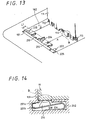
- a charging on/off switch 213 is a spring like switch which can be pressed to the upper and lower direction of the figure and is turned on when the SQ battery pack 1 or battery pack 11 is attached on the mounting face 208 so as to contact with the bottom 115 and pressed by the bottom 115 at a force equal to or more than the repulsion of the spring of the charging on/off switch 213 while sliding in the direction of the arrow A in FIG. 10 and outputs to a microcomputer 271 (FIG. 15).
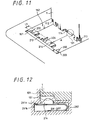
- a type of battery pack deciding switch 214 is a spring like switch which can be pressed to the upper and lower direction of the figure and identifies whether a set battery pack is the conventional battery pack 11 or SQ battery pack 1. As shown in FIG. 8, for example, when the SQ battery pack 1 is attached, the type of battery pack deciding concave portion 131 is provided for a position corresponding to the type of battery pack deciding switch 214 of the SQ battery pack 1 and because of the concave portion, the type of battery pack deciding switch 214 is not pressed by the bottom 115 of the SQ battery pack 1 as shown in FIG. 12 .
- contact points 291a and 291b are kept contacted each other due to the upward repulsion of a spring 292, the electrically connected information is communicated to the microcomputer 271 (FIG. 15), and thereby it is recognized that an attached battery pack is the SQ battery pack 1 under the charging to be described later.
- the type of battery pack deciding switch 214 decides an off state when the contact points 291a and 291b contact.
- the bottom 115 presses the type of battery pack deciding switch 214 at a force equal to or more than the upward repulsion of the spring 292 in FIG. 14.
- the contact points 291a and 291b become non contact state and thereby, become a not electrically connected state.
- the slot 162 is constituted as described above, it is possible to attach the SQ battery pack 1 or battery pack 11 to the battery charger 151.
- the battery attaching portion 3 of the video camera 2 to which the battery pack 11 is attached has the same configuration as the slot 162, so that the explanation thereof is omitted.
- the battery cell 251 of the SQ battery pack 1 is a cell for storing the power supplied from the battery charger 151 by the input/output terminals 112 and 113.
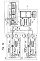
- a microcomputer 252 is constituted of a CPU (Central Processing Unit), RAM (Random Access Memory) and ROM (Read Only Memory), and driven by the power supplied through a reg (regulator) 253.
- the microcomputer 252 collects information about a current supplied to the battery cell 251 which is detected by a resister 256 and a current detector 257, an internal temperature of the SQ battery pack detected by a thermistor 256 and a charging voltage of the cell detected by a voltage detector 258 together with information (of the present time) about the SQ battery pack relating to a charging capacity Q, a charging voltage Vr, a charging standard capacity Qs, an offset voltage Voffset, the corresponding charging mode (The charging mode of the SQ battery pack is super-quick charging mode.) and the like; controls a communication circuit 254; and supplies an output signal to the battery charger 151 by means of the communication terminal 114.
- the charging capacity hereby means a value obtained by multiplying a dischargeable current value and dischargeable time relating to the battery cell 251 in that moment.
- the charging standard capacity means a value obtained by multiplying dischargeable current value and dischargeable time relating to the battery cell 251 at the condition of full charge.
- the microcomputer of the battery charger 151 is constituted of a CPU, a RAM and a ROM to execute various processings of the battery charger 151 and displays various information on the displaying portion 168.
- the communication circuit 272 is controlled by the microcomputer 271 to communicate with either of SQ battery packs 1a and 1b attached to the slots 162a and 162b by a communication switching unit 273.
- the charging changeover switch 274 is controlled by the microcomputer 271 to switch to a terminal 274b or 274c which corresponds to either of the slots 162a and 162b to be charged from a terminal 274a which is a currently resting terminal at the start of charging.
- a charging mode changeover switch 275 is controlled by the microcomputer 271 to switch to the charging mode corresponding to on or off state of the type of battery pack deciding switch 214. More specifically, the charging mode changeover switch 275 is switched from a currently resting terminal 275a to a terminal 275c connected to a quick charging mode power source 277 in case of the battery pack 11 and to a terminal 275c connected to a super-quick charging mode power source 276, the current value of which is larger than that of a quick charging mode in case of the SQ battery pack 1 under charging in accordance with the type of the battery pack set to the slot 162.
- an initial charging mode of super-low current (approximately 100mA)
- This initial charging mode is a mode utilized in the case when the characteristic of the battery cell 251 is deteriorated if it is charged by the nominal current value, for example, when the SQ battery is under over-discharge condition, when a over-discharge protection circuit which is not shown is operated, or the like.
- an AC power source 280 supplies power to the SQ battery pack by converting power supplied through an AC input terminal of outside, which is not shown, to DC power.
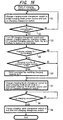
- a step S1 the microcomputer 271 connects the charging mode changeover switch 275 from the terminal 275a connected in the resting state to the terminal 275d to change to the initial charging mode power source 278, and moreover changes the charging changeover switch 274 from the terminal 274a to the terminal 274b and starts charging in the initial charging mode.
- step S2 the microcomputer 271 judges whether or not communication can be made with the SQ battery pack 1 being currently charged in the initial charging mode and continues charging in the initial charging mode until communication can be made.
- step S2 the processing advances to step S3.
- the SQ battery pack 1 receives requests for charging capacity Q, charging voltage Vr, standard charging capacity Qs, pre end voltage Vpre, end voltage Ve and offset voltage Voffset from the microcomputer 271 of the battery charger 151 and transmit those information.
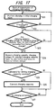
- a step S21 the battery cell 251 is charged (receives power) in the initial charging mode through the processing step S1 in the flowchart in FIG. 16.
- the microcomputer 252a judges whether or not communication can be made and repeats charging through the processing in the step S21 until communication is possible.
- the microcomputer 252a judges in a step S23 whether or not charging capacity Q, charging voltage Vr, standard charging capacity Qs, pre end voltage Vpre, end voltage Ve and offset voltage Voffset are requested from the microcomputer 271 of the battery charger 151 and repeats the processing until they are requested.
- charging capacity Q, charging voltage Vr, standard capacity Qs, pre end voltage Vpre, end voltage Ve and offset voltage Voffset are requested, the process advances to a step S24.
- the microcomputer 252 controls the voltage detector 258, measures the charging voltage Vr, further reads the up to date values of the charging capacity Q, standard charging capacity Qs, pre end voltage Vpre, end voltage Ve and offset voltage Voffset stored in the RAM, controls the communication circuit 254, and transmits the data to the battery charger 151.
- the microcomputer 252 cannot be driven, so that during the above period, only charging is executed through the processing in the step S21, and when the battery pack 1 is charged until the microcomputer 252 can be driven, the started microcomputer 252 judges whether or not communication is possible in the step S22 and executes the judgment of the request in the step S23.
- a step S4 the microcomputer 271 judges whether or not the charging voltage Vr is smaller than the sum of the end voltage Ve and the offset voltage Voffset.
- the microcomputer 271 judges in a step S5 whether or not the charging capacity Q is equal to or more than A% (e.g. A% is equal to 40%) of the standard charging capacity Qs.
- the microcomputer judges that the charging capacity Q is equal to or more than A% of the standard charging capacity Qs, it controls, in a step S6, the communication circuit 272 and transmits to the SQ battery pack 1 a command for making the SQ battery pack 1 rewrite (correct) the charging capacity Q to zero.
- a step S7 the microcomputer 271 controls the charging mode changeover switch 275 to select the terminal 275b and changes the current power source to the super-quick charging mode power source 276 for the super-quick charging mode.
- a step S8 the microcomputer 271 controls the communication circuit 272, judges whether on not charging is completed by the communicating with the SQ battery pack 1, and repeats the processing until charging is completed.
- the microcomputer 271 in a step S9, changes the charging mode changeover switch 275 to the terminal 275a and additionally connects the charging changeover switch 274 to the terminal 274a to complete charging.
- step S4 When it is judged in the step S4 that the charging voltage Vr is not smaller than the sum of the end voltage Ve and offset voltage Voffset, the processing in the step S5 and S6 is skipped and the processing advances to a step S7.
- step S5 when it is judged that the capacity Q is not more than A% of the standard charging capacity Qs, the processing in the step S6 is skipped and the processing advances to the step S7.
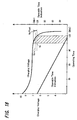
- the charging capacity Q has a small value in a low voltage state (small charging capacity state) in a voltage range (hatched range in FIG. 18) from the end voltage Ve up to the end voltage Ve + offset voltage Voffset in the case that an offset voltage Voffset (e.g. 0.4 V) is set slightly larger than the difference between the pre end voltage Vpre and end voltage Ve, so that if the charging capacity Q transmitted from the SQ battery pack 1 has a large value, it can be said the value includes an error. Therefore, when setting the maximum value of the charging capacity Q to be A% (e.g.
- the stored charging capacity Q is regarded as an incorrect value far away from an actual charging capacity.
- the actual charging capacity Q is regarded as a value close to zero and the value is corrected to zero.
- a charging capacity is corrected to zero in that range by setting an offset voltage Voffset which does not greatly influence on a necessary charging time or allowable operation time.
- a step S25 the microcomputer 252 judges whether or not a command for rewriting the charging capacity Q is received, and when, for example, a command for rewriting a charging capacity to zero is received through the processing in the step S6 in the flowchart of FIG. 16, the microcomputer 252 judges that the command is received and corrects the charging capacity Q stored in the RAM to zero in a step S26.
- a step S27 the microcomputer 252 judges whether or not charging is completed, repeats the processing until charging is completed, and completes the processing when charging is completed.
- step S25 when a command for rewriting a charging capacity is not received, that is, when it is judged in the step S4 in the flowchart of FIG. 16 that the charging voltage Vr is not smaller than the sum of the end voltage Ve and the offset voltage Voffset or it is judged in the step S5 that the charging capacity Q is not more than A% of the standard charging capacity Qs, the processing in the step S26 is skipped.
- the charging voltage of the SQ battery pack 1 has a characteristic in which the charging voltage is maximized when there is no load (supplied current value is zero) and lowers as a load (supplied current value) increases according to the relation between the charging voltage and the charging capacity. Therefore, in the step S24 in the flowchart of FIG. 17, an accurate charging voltage is measured, because a small current supplied from the initial charging mode power source 278 and the load from the battery charger 151 is substantially close to zero.
- the microcomputer 271 of the battery charger 151 judges whether or not the charging capacity Q of the SQ battery pack 1 is a correctly stored value, but it is allowed that the microcomputer 252 of the SQ battery pack 1 judges in accordance with the technique same as the above whether or not its own charging capacity Q is correctly stored and corrects the charging capacity Q by itself when it necessary.
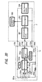
- the battery charger 151 corrects the charging capacity Q, but as shown in FIG. 20, for example, it is also allowed that a unit such as a video camera 2 or the like in which the SQ battery pack 1 supplies power corrects the charging capacity Q.
- a microcomputer 352 constituted by a CPU, a RAM and a ROM controls every operation and a video camera system 354 including the rotational mechanism and recording mechanism of the video camera.
- the microcomputer 352 makes a displaying portion 353 display the information on the SQ battery pack 1.
- the pre end voltage Vpre and the end voltage Ve of the SQ battery pack 1 are stored in the RAM of the microcomputer 352.
- the microcomputer 352 requests to the set SQ battery pack 1 only for the charging voltage Vr through a communication circuit 351 and receives it.
- the microcomputer 352 temporarily stops supply of power from the SQ battery pack 1, measures the voltage opened charging voltage Vr (this is also regarded as the voltage of the power to be supplied to a video camera) under no load state or small load state close to no load state, and receives it (as a result, the accurate charging voltage Vr under a small load is measured).
- the microcomputer 352 judges whether or not the received charging voltage Vr is equal to or lower than the pre end voltage Vpre.
- the microcomputer 352 judges that the received charging voltage Vr is equal to or lower than the pre end voltage Vpre, it makes the SQ battery pack 1 correct the stored charging capacity Q to zero and displays the corrected charging capacity Q on the displaying portion 353. Moreover, when the received charging voltage Vr is not equal to or lower than the pre end voltage Vpre, the microcomputer 352 does not correct the charging capacity Q.
- a case of correcting a charging capacity to zero is described above, but it is not always necessary that a corrected value is equal to zero as long as the value is a value corresponding to zero which shows that a charging capacity is decreased.
- the software is installed in a computer in which a program constituting the software is built in exclusively in a hardware or a general purpose personal computer capable of executing various functions by installing various programs from a program storing medium.
- FIG. 21 shows a configuration of an embodiment of a personal computer for realizing the battery charger 151 by software.
- the CPU 501 of the personal computer controls all operations of the personal computer. Moreover, when a command is input from an input section 506 comprising a keyboard or mouse by a user through a bus 504 and an input/output interface 505, the CPU 501 executes a program stored in a ROM (Read Only Memory) 502 in correspondence with the input command. Moreover, the CPU 501 loads a program read from a magnetic disk 521, an optical disk 522, a magneto-optical disk 523 or a semiconductor memory 524 connected to a drive 510 and installed in a storing section 508 in a RAM (Random Access Memory) 503 to execute the program. Thereby, functions of the above described image processor 1 are realized by software. Moreover, the CPU 501 controls a communication section 509 to communicate with an external unit and execute exchange of data.
- ROM Read Only Memory
- a program storing medium in which programs are recorded is constituted by not only a package medium comprising the magnetic disk 521 (including a floppy disk), the optical disk 522 (including CD-ROM (Compact Disk-Read Only Memory), a DVD (Digital Versatile Disk)), the magnetooptic disk 523 (MD (Mini Disk)), or the semiconductor memory 524 in which programs are recorded and which are distributed to provide programs for users differently from a computer but also constituted by a hard disk included in the ROM 502 and a storing section 508 in which programs are recorded and which is provided for users while previously built in the computer.
- the semiconductor memory 524 in which programs are recorded and which are distributed to provide programs for users differently from a computer but also constituted by a hard disk included in the ROM 502 and a storing section 508 in which programs are recorded and which is provided for users while previously built in the computer.
- a step of describing a program recorded in a program storing medium includes not only processings to be executed in time series along the described sequence but also processings to be executed in parallel or individually instead of being executed in time series.
- a system denotes the whole of an apparatus constituted by a plurality of units.
- a standard charging capacity is stored, the present charging capacity is stored, a charging voltage value is measured, the information on the standard charging capacity, the charging capacity and the charging voltage value is transmitted to a power supplying apparatus, a command for correcting the charging capacity is received from the power supplying apparatus, and the stored charging capacity is corrected in accordance with the received command.
- the information on the standard charging capacity, the charging capacity and the charging voltage value of a charging/discharging apparatus transmitted from the charging/discharging apparatus is received and a command for correcting a charging capacity to zero or a value corresponding to zero is transmitted to the charging/discharging apparatus when the charging voltage value is equal to or less than a predetermined voltage value corresponding to a charging capacity close to zero and the charging capacity has a predetermined rate of the standard charging capacity or more.
- a charging/discharging apparatus stores a standard charging capacity and the present charging capacity, measures a charging voltage value, transmits the information on the standard charging capacity, the charging capacity and the charging voltage value to a power supplying apparatus, receives a command for correcting the charging capacity from the power supplying apparatus, corrects the stored charging capacity in accordance with the received command, and the power supplying apparatus receives the information on the standard charging capacity, the charging capacity and the charging voltage value of the charging/discharging apparatus transmitted from the charging/discharging apparatus and transmits a command for correcting a charging capacity to zero or a value corresponding to zero when the charging voltage value is equal to or lower than a predetermined voltage value corresponding to a charging capacity close to zero and the charging capacity has a predetermined rate of the standard charging capacity or more.
Landscapes
- Engineering & Computer Science (AREA)
- Power Engineering (AREA)
- Charge And Discharge Circuits For Batteries Or The Like (AREA)
- Tests Of Electric Status Of Batteries (AREA)
- Secondary Cells (AREA)
Abstract
In case of the present invention, a microcomputer
(271) controls a charging mode changeover switch (275) and
connects the switch to a terminal (275d) to change the
terminal (275d) to an initial charging mode power source
(278). In this case, the microcomputer (271) requests the
information on the charging capacity stored in a
microcomputer (252) as charging information, the charging
voltage measured by a voltage detector (258) and a standard
charging capacity and obtains the information through a
communication circuits (254) and (272). The microcomputer
(271) obtains an actual charging capacity in accordance
with a received measured charging voltage, compares the
actual charging capacity with a stored charging capacity,
and updates the actual charging capacity to zero when the
comparison result is equal to or larger than a threshold
value and the charging voltage is equal to or less than
another threshold value. According to the present
invention, a charging capacity is correctly corrected.
Description
The present invention relates to a
charging/discharging apparatus and method, a power
supplying apparatus and method, a power supplying system
and method, a program storing medium, and a program; and
particularly to a charging/discharging apparatus and method,
power supplying apparatus and method, a power supplying
system and method, a program storing medium, and a program
where the charging capacity of a charging/discharging
apparatus can accurately be corrected.
A so called charging/discharging technique is
generally becoming popular in which power is supplied from
such a power supplying apparatus as a battery charger to a
charging/discharging apparatus represented by a battery
pack used in a video camera or the like to charge the same.
As a recent battery pack, a battery pack of such
a type where a microcomputer is incorporated therein and
the charging capacity of the battery pack is memorized or
stored in the computer has been provided for a practical
use. In the battery pack of this type, the computer causes
a built-in RAM (Random Access Memory), an EEPROM
(Electrically Erasable Programmable Read Only Memory), a
ROM (Read Only Memory) or the like to store data or
information on the charging capacity of a battery pack now
on use. When this battery pack is set to a video camera or
a battery charger, the microcomputer reads out the stored
information on the charging capacity to transmit the
information to the video camera or the battery charger. On
the other hand, the operation time or the charging time of
the battery pack is calculated on the basis of this
information and displayed in the video camera or the
battery charger.
Regarding the power charged in a battery pack,
however, it has been known that, even though the battery
pack which has just charged had a charging capacity from
which an allowable operation time of 120 minutes is
calculated, for example, as shown in Fig. 1, when the
battery pack is left in a non-use state for a long time,
the battery pack gradually self-discharges. For example,
when the charged battery pack is put in a non-use state for
six months, the charging capacity of the battery pack
stored in a memory is 120 minutes but its actual charging
capacity is reduced to about 10% of the charging capacity
stored in the memory.
In general, the allowable operation time of a
battery pack has a relationship with the charging voltage
of the battery pack shown in Fig. 2. That is, in case of
the charging capacity of a battery pack which can drive a
video camera for 120 minutes at maximum, for example,
indication of about 8.4V shows a full charged state (100%
charged state), and a time display of 120 minutes is
performed as the allowable operation time. Then, the
charging voltage and the allowable operation time decreases
as an operating time elapses. Here, a pre-end voltage Vpre
(Voltage Pre-end) (for example, 6.7 V) in Fig. 2 is a
voltage value indicating that only a short allowable
operation time is left. That is, when the allowable
operation time becomes zero, there may occurs a problem
that a saving operation can not be performed safely during
execution of various processing. Under such circumstances,
the pre-end voltage Vpre is set for warning a user in a
state the allowable operation time is still left before the
charging voltage reaches an end voltage Ve (Voltage end)
(for example, 6.5V: a voltage at which a video camera or
the like can not be driven) in order to prompt the user to
perform a saving operation safely.
However, when the battery pack fully charged is
kept in a non-operation state for a long time, the
relationship between the charging time and the allowable
operation time varies due to self-discharging of the
battery pack, for example, as shown in Fig. 3. That is,
since the charging voltage is changed to a lowered state
(the charging capacity is reduced) due to the self-discharging,
which results in reduction in actual allowable
operation time. Even in this state, however, since the
allowable operation time at a full charged state has been
stored in the RAM, there is a problem that, though an
actual allowable operation time is 30 minutes or so, the
allowable operation time indication displays about 80
minutes, which causes an error. Incidentally, the
allowable charging capacity has been actually stored in the
RAM, and the allowable operation time is computed in the
battery charger or the like on the basis of the allowable
charging capacity to be displayed.
Also, as a method for detecting a self-discharge
of a battery pack in case that the battery pack is left for
a long time without using the same, there is a method where
the state of a battery pack while it is not operated is
monitored by a microcomputer in the battery pack and a
self-discharged amount corresponding to the monitored state
is reduced from the original charged state so that an error
in an allowable operation time display of the battery is
corrected. At this time, a power source for driving the
microcomputer in the battery pack uses the power of the
battery pack.
However, in case that the self-discharged amount
due to the long term non-use is detected by the
microcomputer in the battery pack, there occurs a case that
a power more than that discharged due to the self-discharging
of the battery pack is consumed for driving the
microcomputer, and therefore a problem occurs that a non-use
time of the battery pack must be significantly reduced.
Furthermore, there is a problem that an overdischarged
state occurs in that the voltage of the battery
pack is discharged below a voltage level required for
maintaining functions of the battery pack, which injures a
safety or a reliability of the battery pack.
As set forth above, it is considered to be
desirable that the microcomputer in the battery pack is
controlled to a non-operation state (microcomputer sleep)
in a state that the battery pack is not used (a state that
charging and discharging are not conducted).
The present invention has been made in view of
these circumstances, and an object thereof is to perform
correction such that an allowable operation time of a
battery pack can be displayed accurately.
A first charging/discharging apparatus of the
present invention is characterized by comprising standard
charging capacity storing means for storing a standard
charging capacity, charging capacity storing means for
storing the present charging capacity, charging voltage
value measuring means for measuring a charging voltage
value, transmitting means for transmitting the information
on a standard charging capacity, a charging capacity and a
charging voltage value to a power supplying apparatus,
receiving means for receiving a command for correcting a
charging capacity form the power supplying apparatus, and
correcting means for correcting the stored charging
capacity based on the received from the receiving means.
It is possible to make the charging voltage value
measuring means measure a charging voltage value when the
value of the current of the power supplied from a power
supplying apparatus is zero or a sufficiently small value
close to zero.
When the charging voltage value is a
predetermined voltage value corresponding to a charging
capacity close to zero or less and the charging capacity
stored by the charging capacity storing means has a
predetermined rate of a standard charging capacity or more,
it is possible to make the correcting means correct the
stored charging capacity to zero or a value corresponding
to zero.
It is possible to further provide current value
measuring means for measuring the charging current value or
discharging current value.
It is possible to make the current value
measuring means measure a charging current value or a
discharging current value when the power supplied from a
power supplying apparatus is equal to zero or a
sufficiently small value close to zero.
When the charging current value is equal to or
less than a predetermined current value corresponding to a
charging capacity close to zero and the charging capacity
stored by the charging capacity storing means has a
predetermined rate of a standard charging capacity or more,
it is possible to make the correcting means correct the
stored charging capacity to zero.
It is possible to make the transmitting means
further transmit not only the information on a standard
charging capacity, a charging capacity and a charging
voltage value but also a charging current value, a
discharging current value or temperature data to a power
supplying apparatus.
A first charging/discharging method of the
present invention is characterized by including a standard
charging capacity storing step of storing a standard
charging capacity, a charging capacity storing step of
storing the present charging capacity, a charging voltage
value measuring step of measuring a charging voltage value,
a transmitting step of transmitting the information on a
standard charging capacity, a charging capacity and a
charging voltage value to a power supplying apparatus, a
receiving step of receiving a command for correcting a
charging capacity from the power supplying apparatus, and a
correcting step of correcting the stored charging capacity
based on the command received through the processing in the
receiving step.
A program of a first program storing medium of
the present invention is characterized by including a
standard charging capacity storage controlling step of
controlling storage of a standard charging capacity, a
charging capacity storage controlling step of controlling
storage of the present charging capacity, a charging
voltage value measurement controlling step of controlling
measurement of a charging voltage value, a transmission
controlling step of controlling transmission of the
information on a standard charging capacity, charging
capacity, and charging voltage value to a power supplying
apparatus, a reception controlling step of controlling
reception of a command for correcting a charging capacity,
and a correction controlling step of controlling correction
of the stored charging capacity.
A first program of the present invention is
characterized by executing a standard charging capacity
storage controlling step of controlling storage of a
standard charging capacity, a charging capacity storage
controlling step of controlling storage of the present
charging capacity, a charging voltage value measurement
controlling step of controlling measurement of a charging
voltage value, a transmission controlling step of
controlling transmission of the information on a standard
charging capacity, a charging capacity and a charging
voltage value to a power supplying apparatus, a reception
controlling step of controlling reception of a command for
correcting a charging capacity and a correction controlling
step of controlling correction of the stored charging
capacity.
A power supplying apparatus of the present
invention is characterized by comprising receiving means
for receiving the information on the standard charging
capacity, the charging capacity and the charging voltage
value of a charging/discharging apparatus transmitted from
the charging/discharging apparatus and transmitting means
for transmitting a command for correcting a charging
capacity to zero or a value corresponding to zero to the
charging/discharging apparatus when a charging voltage
value is equal to or less than a predetermined voltage
value corresponding to a charging capacity close to zero
and the charging capacity has a predetermined rate of the
standard charging capacity or more.
It is possible to further provide current
controlling means for controlling the current value of the
power to be supplied to the charging/discharging apparatus
and set a charging voltage value to a value when a current
is controlled to zero or a sufficiently small value close
to zero by current controlling means.
It is possible to make the receiving means
receive not only a standard charging capacity, a charging
capacity and a charging voltage value but also a charging
current value or a discharging current value transmitted
from a charging/discharging apparatus.
It is possible to further provide current
controlling means for controlling the value of the power to
be supplied to the charging/discharging apparatus and set a
charging current value or a discharging current value to a
value when the current value is controlled to zero of a
sufficiently small value close to zero by current
controlling means.
A power supplying method of the present invention
is characterized by including a receiving step of receiving
the information on the standard charging capacity, the
charging capacity and the charging voltage value of a
charging/discharging apparatus transmitted from the
charging/discharging apparatus and a transmitting step of
transmitting a command for correcting a charging capacity
to zero or a value corresponding to zero when a charging
voltage value is equal to or less than a predetermined
voltage value corresponding to a charging capacity close to
zero and the charging capacity has a predetermined rate of
the standard charging capacity or more.
A program of a second program storing medium of
the present invention is characterized by including a
reception controlling step of controlling reception of the
information on the standard charging capacity, the charging
capacity and the charging voltage value of a
charging/discharging apparatus transmitted from the
charging/discharging apparatus and a transmission
controlling step of controlling transmission of a command
for correcting a charging capacity to zero or a value
corresponding to zero when the charging capacity has a
predetermined rate of the standard charging capacity or
more.
A second program of the present invention is
characterized by executing a reception controlling step of
controlling reception of the information on the standard
charging capacity, the charging capacity and the charging
voltage value of a charging/discharging apparatus
transmitted from the charging/discharging apparatus and a
transmission controlling step of controlling transmission
of a command for correcting a charging capacity to zero or
a value corresponding to zero when the charging voltage
value is equal to or less than a predetermined voltage
value corresponding to a charging capacity close to zero
and the charging capacity has a predetermine rate of the
standard charging capacity.
A first power supplying system of the present
invention is characterized in that a charging/discharging
apparatus is provided with standard charging capacity
storing means for storing a standard charging capacity,
charging capacity storing means for storing the present
charging capacity, charging voltage value measuring means
for measuring a charging voltage value, first transmitting
means for transmitting the information on a standard
charging capacity, charging capacity, and charging voltage
value to a power supplying apparatus, first receiving means
for receiving a command for correcting the charging
capacity from the power supplying apparatus, and correcting
means for correcting the stored charging capacity in
accordance with the command received by the first receiving
means; and the power supplying apparatus is provided with
second receiving means for receiving the standard charging
capacity, charging capacity, and charging voltage value of
the charging/discharging apparatus transmitted from the
charging/discharging apparatus and second transmitting
means for transmitting a command for correcting the
charging capacity to zero or a value corresponding to zero
when the charging voltage value is equal to or less than a
predetermined voltage value corresponding to a charging
capacity close to zero and the charging capacity has a
predetermined rate of the standard charging capacity or
more.
A power supplying method of a first power
supplying system of the present invention is characterized
in that a charging/discharging method of a
charging/discharging apparatus includes a standard charging
capacity storing step of storing a standard charging
capacity, a charging capacity storing step of storing the
present charging capacity, a charging voltage value
measuring step of measuring a charging voltage value, a
first transmitting step of transmitting the information on
a standard charging capacity, a charging capacity and a
charging voltage value to a power supplying apparatus, a
first receiving step of receiving a command for correcting
the charging capacity from the power supplying apparatus,
and a correcting step of correcting the stored charging
capacity based on the command received through the
processing in the first receiving step; and a power
supplying method of the power supplying apparatus includes
a second receiving step of receiving the standard charging
capacity, the charging capacity and the charging voltage
value of the charging/discharging apparatus transmitted
from the charging/discharging apparatus and a second
transmitting step of transmitting a command for correcting
the charging capacity to zero or a value corresponding to
zero when the charging voltage value is equal to or less
than a predetermined voltage value corresponding to a
charging capacity close to zero and the charging capacity
has a predetermined rate of the standard charging capacity
or more.
A program of a third program storing medium of
the present invention is characterized in that a program
for controlling a charging/discharging apparatus includes a
standard charging capacity storage controlling step of
controlling storage of a standard charging capacity, a
charging capacity storage controlling step of controlling
storage of the present charging capacity, a charging
voltage value measurement controlling step of controlling
measurement of a charging voltage value, a fist
transmission controlling step of controlling transmission
of the information on a standard charging capacity, a
charging capacity and a charging voltage value to a power
supplying apparatus, a first reception controlling step of
controlling reception of a command for correcting the
charging capacity from the power supplying apparatus, and a
correction controlling step of controlling correction of
the stored charging capacity in accordance with the command
received through the processing in the first reception
controlling step; and a program for controlling the power
supplying apparatus includes a second reception controlling
step of controlling reception of the information on the
standard charging capacity, charging capacity, and charging
voltage value of the charging/discharging apparatus
transmitted from the charging/discharging apparatus and a
second transmission controlling step of controlling
transmission of a command for correcting a charging
capacity to zero or a value corresponding to zero when the
charging voltage value is equal to or less than a
predetermined voltage value corresponding to a charging
capacity close to zero and the charging capacity has a
predetermined rate of the standard charging capacity or
more.
A third program of the present invention is
characterized by making a computer for controlling a
charging/discharging apparatus execute a standard charging
capacity storage controlling step of controlling storage of
a standard charging capacity, a charging capacity storage
controlling step of controlling storage of the present
charging capacity, a charging voltage value measurement
controlling step of controlling measurement of a charging
voltage value, a first transmission controlling step of
controlling transmission of the information on a standard
charging capacity, a charging capacity and a charging
voltage value to a power supplying apparatus, a first
reception controlling step of controlling reception of a
command for correcting a charging capacity from the power
supplying apparatus, and a correction controlling step of
controlling correction of a charging capacity based on the
command received through the processing in the first
reception controlling step; and a computer for controlling
the power supplying apparatus execute a second reception
controlling step of controlling reception of the
information on the standard charging capacity, the charging
capacity and the charging voltage value of the
charging/discharging apparatus transmitted from the
charging/discharging apparatus and a second transmission
controlling step of controlling transmission of a command
for correcting a charging capacity to zero or a value
corresponding to zero when the charging capacity has a
predetermined rate of the standard charging capacity.
In case of charging/discharging apparatus and
method and a program of the present invention, a standard
charging capacity is stored, the present charging capacity
is stored, a charging voltage value is measured, the
information of the standard charging capacity, the charging
capacity and the charging voltage value are transmitted to
a power supplying apparatus, and a command for correcting a
charging capacity is received from the power supplying
apparatus and the stored charging capacity is corrected
based on the received command.
In case of power supplying apparatus and method
and a program of the present invention, the standard
charging capacity, the charging capacity and the charging
voltage value of a charging/discharging apparatus
transmitted from the charging/discharging apparatus are
received and a command for correcting a charging capacity
to zero or a value corresponding to zero is transmitted to
the charging/discharging apparatus when a charging voltage
value is equal to or less than a predetermined voltage
value corresponding to a charging capacity close to zero
and the charging capacity has a predetermined rate of the
standard charging capacity or more.
In case of power supplying system and method and
a program of the present invention, a charging/discharging
apparatus stores a standard charging capacity and the
present charging capacity, measures a charging voltage
value, and transmits the information on a standard charging
capacity, a charging capacity and a charging voltage value
to a power supplying apparatus; and a power supplying
apparatus receives a command for correcting a charging
capacity, corrects the stored charging capacity based on
the received command, receives the information on the
standard charging capacity, the charging capacity and the
charging voltage value of the charging/discharging
apparatus transmitted from the charging/discharging
apparatus, and transmits a command for correcting a
charging capacity to zero or a value corresponding to zero
to the charging/discharging apparatus when the charging
voltage value is equal to or less than a predetermined
voltage value corresponding to a charging capacity close to
zero and the charging capacity has a predetermined rate of
the standard charging capacity.
FIG. 4 is a view showing a configuration of an
embodiment of a SQ (Super-quick) battery pack 1 of the
present invention. The SQ battery pack 1 is set to a
battery attaching portion 3 of a video camera 2. The SQ
battery pack 1 is attached to the battery attaching portion
3 of the video camera 2 to supply power to the video camera
2. Moreover, with reference to FIG. 8, the SQ battery pack
1 is constituted such that it can be attached to a battery
charger 151 to be described later, which is charged by the
battery charger 151. Moreover, a conventional battery pack
11 (FIG. 7) can be set to the battery attaching portion 3.
The charging time of the SQ battery pack 1 is shorter than
that of the conventional battery pack 11, because it can be
charged at a larger current when it is charged by the
battery charger 151.
Then, details of the SQ battery pack 1 are
described below with reference to FIG. 5. As shown in FIG.
5, a case 101 ,which stores a battery cell 251a or 251b
with reference to FIG. 15, is provided in the pack 1.
The case 101 of the SQ battery pack 1 is formed
by a synthetic resin. Guide grooves 102a to 102d (FIG. 6)
for guiding the battery attaching portion 3, or slots 162a
or 162b of battery charger 151 in the attaching direction
shown by the arrow A in FIG. 5 are formed on the width
directional both side faces of the case 101. In FIG. 5 ,
only the guide grooves 102a and 102b are shown.
In the following description, the guide grooves
102a to 102d are referred to as the guide 102 when it is
not necessary to individually distinguish the guide grooves
102a to 102d. The same is applied to other configurations.
As shown in FIG. 6, each guide groove 102 on each
side face is formed while one end of the groove 102 is
opened on the bottom 115 of the case 101 and formed in the
longitudinal direction of the case 101 in parallel.
Input/ output terminals 112 and 113 are formed at
the width directional both sides of the case 101 at the
front portion 111 shown by the direction of the arrow A in
FIG. 6 to the battery attaching portion 3 or a slot 162 of
the battery charger 151 and a communication terminal 114 is
attached to the approximate center in the width direction.
The input/ output terminals 112 and 113 receive
power from the battery charger 151 and at the same time
supply power to the video camera 2 via terminals not shown.
The communication terminal 114 communicates with the
battery charger 151 or the video camera 2 relating the
information such as the charging capacity, the standard
charging capacity and the charging voltage of and SQ
battery pack 1. Outward one ends of the input/ output
terminals 112 and 113 and communication terminal 114 are
located in an approximately rectangular concave portion
formed at the front portion 111 of the case 101. Therefore,
the battery attaching portion 3 or the battery charger 151
is prevented from being broken due to the contact with a
portion other than each connection terminal.
A pair of controlling concave portions 116 and
117 are formed on the front portion 111 in the setting
direction (front portion in longitudinal direction) shown
by the arrow A in FIG. 6 at the bottom 115 of the case 101.
As shown in FIG. 6, these controlling concave portions 116
and 117 are formed so as to be line symmetric to the
approximate center line (not illustrated) in the transverse
direction. For setting, these controlling concave portions
116 and 117 are engaged with controlling convex portions
206 and 207 of the battery charger 151 (FIG. 10) to control
the width directional tilt of the bottom 115 of the case
101 from the slots 162.
As shown in FIG. 6, the controlling concave
portions 116 and 117 are respectively provided with a first
portion formed perpendicularly to the bottom 115 of the
case 101 and a second portion formed perpendicularly to the
first portion and whose cross sections are respectively
formed like L shape. Moreover, an approximately
rectangular identifying concave portion 118 for identifying
the adaptive slot 162 is formed at the approximate center
of the bottom 115 of the case 101.
As shown in FIG. 6, the identifying concave
portion 118 is formed on the approximate center line of the
case 101 in its width direction and located at the front
portion 111 at the approximate center of the bottom 115 of
the case 101. An approximately rectangular identifying
groove 119 is continuously formed at the longitudinal
directional both ends on the approximate width directional
center line of the case 101 at the bottom of the inside of
the identifying concave portion 118. A stepped portion is
formed at the width directional both sides of the bottom
115 of the case 101 in the identifying concave portion 118.
The dimension of the width-directional both sides of the identifying concave portion 118 is formed at the dimension widthWO (WO is a predetermined dimension).
Moreover, a guide groove 120 adjacent to the
communication terminal 114 is formed in parallel with the
longitudinal direction of the case 101. One end of the
guide groove 120 opens at the front portion 111 of the case
101 and the other end of it is formed by being continued
with the identifying concave portion 118. Stepped portions
121 different from each other in depth are formed on the
guide groove 120 in the direction perpendicular to the
bottom 115 of the case 101 at the position adjacent to the
front portion 111 of the case 101. The guide groove 120
guides the SQ battery pack 1 in the setting direction shown
by the arrow A to the slot 162 of the battery charger 151.
As shown in FIG. 6, a guide groove 122 is formed
at the position opposite to the guide groove 120 at the
both sides of the communication terminal 114. The guide
groove 122 is formed in parallel with the longitudinal
direction of the bottom 115 of the case 101.
A controlling groove 103 (though not illustrated,
another groove 103 is also formed at the same position of
the left side face of the front portion 111) adjacent to
the input/ output terminals 112 and 113 is formed at the
width directional both side faces of the case 101. The
controlling groove 103 opens at the front portion 111 and
is formed in approximately parallel with the bottom 115 to
control the width directional tilt of the bottom 115 from
the slots 162.
A small locking concave portion 124 and a large
locking concave portion 125 to be engaged with the slot 162
are formed on the bottom 115 of the case 101 when the
bottom 115 is attached to the battery charger 151. The
small locking concave portion 124 is formed into an
approximate rectangle on the approximate center line of the
case 101 in its width direction so as to be adjacent to the
identifying concave portion 118. The large locking concave
portion 125 is formed into an approximate rectangle
slightly larger than the small locking concave portion 124
at the back side in the attaching direction on the
approximate center line of the case 101 in its width
direction.
A type of battery pack deciding concave portion
131 serves as a concave portion for identifying the SQ
battery pack 1 and the battery pack 11 when the portion 131
is attached to the slot 162 of the battery charger 151. As
shown in FIG. 7, in case of the type of battery pack
deciding concave portion 131, a concave portion is formed
on the portion shown by B of the conventional battery pack
11 in FIG. 7 by the same depth as the guide groove 122 and
the same length as the longitudinal direction of the
controlling portion 117 when viewed from the bottom 115.
That is, the type of battery pack deciding concave portion
131 has a configuration in which a part of the bottom 115
of the conventional battery pack 11 is cut out. Because
the difference between shapes of the conventional battery
pack 11 and SQ battery pack 1 lies in only presence or
absence of the type of battery pack deciding concave
portion 131, other description is omitted.
Then, the configuration of the battery charger
151 is described below with reference to FIG. 8.
It is possible to attach two battery packs to the
battery charger 151. Moreover, terminal shutters 161a and
161b of the battery charger 151 are flat. Therefore, when
the SQ battery pack 1 or the battery pack 11 is not
attached, the shutters 161a and 161b are pushed out in the
direction opposite to the direction of the arrow A in FIG.
8 due to the repulsion of a not illustrated spring built in
the body of the battery charger 151 and fixed at a
predetermined length to cover terminal portions of the
battery charger 151 to be described later. Moreover, when
the SQ battery pack 1 or battery pack 11 is attached along
the slot 162 and the terminal shutters 161 are pushed
against the repulsion of a not illustrated spring by the
front portion 111, the shutters 161 slide in the direction
of the arrow A in FIG. 8 and are stored in the body of the
battery charger 151. Thus, because the terminal shutters
161 are stored, the terminal portion of the battery charger
151 is exposed and moreover, the SQ battery pack 11 or
battery pack 1 is attached (connected). Details of the
slot 162 will be described later.
A DC (Direct Current) input terminal 163 is a
terminal to which a not illustrated cable for supplying
power to the battery charger 151 is attached and rated
power is supplied. A DC output terminal 164 is a terminal
to which a not illustrated cable for outputting the power
supplied from the DC input terminal 163 to a video camera 2
is attached and which outputs the power at a voltage value
and a current value corresponding to the video camera 2. It
should be noted that an AC (Active Current) input terminal
is also provided therein.
A mode changing switch 166 is a switch for
changing operation modes of the battery charger 151 and
selecting either of the mode to output to a video camera
set to the DC output terminal 164 and the mode to charge a
battery pack attached to the slots 162.
A charging mode lamp 167 shows two modes while
the battery charger 151 performs charging. One of them is
a quick charging mode for charging the conventional battery
pack 11 and the other of them is a super-quick charging
mode for charging the SQ battery pack 1. The super-quick
charging mode is a charging mode to quickly perform
charging at a large current compared to the case of the
quick charging mode.
A display portion 168 is constituted of a LCD
(Liquid Crystal Display) or the like to display a charged
state or other information.
FIG. 9 shows details of the displaying portion
168. FIG. 9 shows a state in which all portions which can
be displayed as an LCD are displayed. Therefore, a part of
the display in FIG. 9 is actually displayed.
A charging trouble displaying portion 181 is a
portion showing "charging trouble" located at the top left
of the displaying portion 168, which is displayed when a
trouble is detected in the set SQ battery pack 1 or battery
pack 11 while it is charged.
A remaining charging time displaying portion 182
displays a remaining charging time, on which a message "up
to end of practical use charging" is displayed when showing
a practical use charged state, that is, the time up to an
operable charged state, a message "up to end of full
charging" when showing the charging time until completely
charged in the display "up to end of practical use full
charging" and in this case, the time up to end of each
charging is displayed on a time displaying portion 183.
An allowable operation time displaying portion
184 is displayed when displaying the allowable operation
time of the SQ battery pack 11 or battery pack 11 and in
this case, a corresponding allowable operation time is
displayed on the time displaying portion 183.
A video camera displaying portion 185 is
displayed in a mode in which power is supplied to the video
camera 2 by the mode changing switch 166.
A full charge displaying portion 186 is displayed
when the attached SQ battery pack 1 or battery pack 11 is
fully charged (charging capacity of 100%). A battery mark
187 displays a charged state of the SQ battery pack 1 or
battery pack 11, in which a displayed portion increases as
the current charged state approaches a fully charged state
and the displayed portion decreases when a charged capacity
is small.
The battery charger 151 in FIG. 8 is described
below again.
A charge slot displaying lamp 169 is constituted
of two lamps showing the slots 162a and 162b respectively
and is a lamp showing that the displaying portion 168 shows
the information on an attached battery pack.
A display changing button 170 is a button for
changing displayed contents of the displaying portion 168
whenever the display charging button is pressed. Whenever
pressing the display charging button, the displayed slot
162 is changed (change of charge slot lamp 169) and the
time display up to end of charging and the allowable
operation time display are changed.
Then, the detailed configuration of the slot 162
is described below with reference to FIG. 10. The slot
162a and 162b have the same configuration.
The slot 162 is formed so as to be slightly
larger than the shape of the bottom 115 of the SQ battery
pack 1 or battery pack 11. The slot 162 has a pair of
guide convex portions 201a and 201b engaged with each guide
groove 102 of the SQ battery pack 1 of battery pack 11
adjacently to a mounting face 208 at each side opposite to
the width directional both sides of the SQ battery pack 1
of battery pack 11. Though not illustrated, two guide
portions 201a and 201b are further provided at opposed
positions to the width direction of the slots 162.
The guide convex portions 201 are inserted into
the guide grooves 102 of the case 101 respectively when
attaching the SQ battery pack 1 or battery pack 11.
Thereby, the slot 162 guides an inserting direction by
making the bottom 115 of the case 101 approximately
parallel with the mounting face 208 and hold the SQ battery
pack 1 or battery pack 11.
When setting the SQ battery pack 1 or battery
pack 11, connection terminals 202 and 203 and a
communication terminal 204 are arranged on the bumping face
205 of a slot opposite to the front portion 111. These
terminals are usually covered under a state in which the
terminal shutter 161 slides up to the same position as the
right side in FIG. 10 where the controlling convex portions
206 and 207 become L shape in the direction opposite to the
direction of the arrow A and protected from an impact or
the like. FIG. 10 shows a state in which the terminal
shutter 168 slides in the direction of the arrow A and is
housed in the body of the battery charger 151.
The connection terminals 202 and 203 are located
at the width directional both sides of the slot 162 and
connected to the input/ output terminals 112 and 113 of the
SQ battery pack 1 or battery pack 11 respectively. The
communication terminal 204 is located at the approximate
center of the slot 162 in its width directions and
connected to the communication terminal 114 of the battery
pack 1. The connection terminals 202 and 203 and the
communication terminal 204 are arranged on the bumping face
205 of the slot 162 in parallel with the bottom 115 of the
SQ battery pack 1 or battery pack 11 and in parallel with
the longitudinal direction of the SQ battery pack 1 or
battery pack 11.
Moreover, a pair of controlling convex potions
206 and 207 engaged with the controlling concave portions
116 and 117 of the SQ battery pack 1 or battery pack 11
respectively while bestriding the bumping face 205 and
mounting face 208 are respectively integrally formed on the
slot 162 line symmetrically to the approximate center line
in the width direction.
These controlling convex portions 206 and 207
respectively have a first portion formed perpendicularly to
the mounting face 208 and a second portion formed
perpendicularly to the first portion and whose cross
sections respectively show an approximate L shape. These
controlling convex portions 206 and 207 control that the
bottom 115 of the battery pack 11 is tilted from the
mounting face 208 of the slot 162 in the width direction.
Moreover, a guide convex portion 210 for guiding
the inserting direction of the SQ battery pack 1 or battery
pack 11 are integrally formed at a position adjacent to the
communication terminal 204 while bestriding the bumping
face 205 and mounting face 208. As shown in FIG. 10, the
guide convex portion 210 is formed in parallel with the
longitudinal direction of the mounting face 208 at a
position engaged with the guide groove 120 at the bottom
115 of the SQ battery pack 1 or battery pack 11 to be
attached.
Furthermore, a guide convex portion 211 for
guiding the attaching direction of the SQ battery pack 1 or
battery pack 11 is formed on the slot 162 in parallel with
the longitudinal direction of the mounting face 208 while
bestriding the bumping face 205 and mounting face 208. The
guide convex portion 211 guides the setting direction by
engaging with the guide groove 122 of the SQ battery pack 1
or battery pack 11.
Furthermore, a controlling pawl 209 engaging with
a controlling groove 123 is integrally protruded and formed
at the width directional both sides of the slot 162
respectively. The controlling pawl 209 is formed in
parallel with the mounting face 208 and the longitudinal
direction of the SQ battery pack 1 or battery pack 11.
Though not illustrated, one more controlling pawl 209 is
formed on an opposed face to the width direction of the
slot 162.
Furthermore, an identifying convex portion 212
engaging with the identifying convex portion 118 for
identifying whether the SQ battery pack 1 or battery pack
11 can be charged is integrally formed with the slot 162 at
the approximate center of the mounting face 208. The
identifying convex portion 212 is formed into an
approximate rectangular parallelepiped. A convex piece
212a engaging with the identifying groove 119 of the SQ
battery pack 1 or battery pack 11 is integrally formed at
the front end of the identifying convex portion 212.
Furthermore, as shown in FIG. 10, the identifying convex
portion 212 is formed such that the dimension of the
mounting face 208 parallel with the width direction becomes
equal to a width W1 smaller than the width W0 of the
identifying concave portion 118 of the SQ battery pack 1 or
battery pack 11 and the portion 212 can be inserted into
the identifying concave portion 118. Furthermore, the
identifying convex portion 212 is formed at a position
separate by a predetermined distance in the direction
orthogonal to the bumping face 205.
A charging on/off switch 213 is a spring like
switch which can be pressed to the upper and lower
direction of the figure and is turned on when the SQ
battery pack 1 or battery pack 11 is attached on the
mounting face 208 so as to contact with the bottom 115 and
pressed by the bottom 115 at a force equal to or more than
the repulsion of the spring of the charging on/off switch
213 while sliding in the direction of the arrow A in FIG.
10 and outputs to a microcomputer 271 (FIG. 15).
A type of battery pack deciding switch 214 is a
spring like switch which can be pressed to the upper and
lower direction of the figure and identifies whether a set
battery pack is the conventional battery pack 11 or SQ
battery pack 1. As shown in FIG. 8, for example, when the
SQ battery pack 1 is attached, the type of battery pack
deciding concave portion 131 is provided for a position
corresponding to the type of battery pack deciding switch
214 of the SQ battery pack 1 and because of the concave
portion, the type of battery pack deciding switch 214 is
not pressed by the bottom 115 of the SQ battery pack 1 as
shown in FIG. 12 . In this case, contact points 291a and
291b are kept contacted each other due to the upward
repulsion of a spring 292, the electrically connected
information is communicated to the microcomputer 271 (FIG.
15), and thereby it is recognized that an attached battery
pack is the SQ battery pack 1 under the charging to be
described later. The type of battery pack deciding switch
214 decides an off state when the contact points 291a and
291b contact.
Moreover, as shown in FIG. 13, when the
conventional battery pack 11 is attached, the portion B
having no concave portion shown in FIG. 7 slides to a
position corresponding to the type of battery pack deciding
switch 214 of the battery pack 11 in the direction of the
arrow A in FIG. 13. Therefore, as shown in FIG. 14, the
bottom 115 presses the type of battery pack deciding switch
214 at a force equal to or more than the upward repulsion
of the spring 292 in FIG. 14. In this case, the contact
points 291a and 291b become non contact state and thereby,
become a not electrically connected state. When the above
information is communicated to the microcomputer 271 (FIG.
15) and thereby, it is recognized that a set battery pack
is the conventional battery pack 11 under the charging to
be described later. The type of battery pack deciding
switch 214 decides the on state when the contact points
291a and 291b are kept in a non contact state.
Since the slot 162 is constituted as described
above, it is possible to attach the SQ battery pack 1 or
battery pack 11 to the battery charger 151.
The battery attaching portion 3 of the video
camera 2 to which the battery pack 11 is attached has the
same configuration as the slot 162, so that the explanation
thereof is omitted.
Then, an electrical configuration (first
configuration) of the SQ battery pack 1 and battery charger
151 is described below with reference to FIG. 15. The SQ
battery pack 1 is attached to the slots 162a and 162b in
FIG. 15 and the both configurations are the same.
The battery cell 251 of the SQ battery pack 1 is
a cell for storing the power supplied from the battery
charger 151 by the input/ output terminals 112 and 113.
A microcomputer 252 is constituted of a CPU
(Central Processing Unit), RAM (Random Access Memory) and
ROM (Read Only Memory), and driven by the power supplied
through a reg (regulator) 253. The microcomputer 252
collects information about a current supplied to the
battery cell 251 which is detected by a resister 256 and a
current detector 257, an internal temperature of the SQ
battery pack detected by a thermistor 256 and a charging
voltage of the cell detected by a voltage detector 258
together with information (of the present time) about the
SQ battery pack relating to a charging capacity Q, a
charging voltage Vr, a charging standard capacity Qs, an
offset voltage Voffset, the corresponding charging mode
(The charging mode of the SQ battery pack is super-quick
charging mode.) and the like; controls a communication
circuit 254; and supplies an output signal to the battery
charger 151 by means of the communication terminal 114. The
charging capacity hereby means a value obtained by
multiplying a dischargeable current value and dischargeable
time relating to the battery cell 251 in that moment. In
addition the charging standard capacity means a value
obtained by multiplying dischargeable current value and
dischargeable time relating to the battery cell 251 at the
condition of full charge. Though the conventional battery
pack 11 has the same configuration, it cannot be charged at
a large current compared to the SQ battery pack 1, because
the characteristic of the battery cell 251 is different.
Then, an electrical configuration example (first
configuration) of the battery charger 151 is described
below.
The microcomputer of the battery charger 151 is
constituted of a CPU, a RAM and a ROM to execute various
processings of the battery charger 151 and displays various
information on the displaying portion 168. The
communication circuit 272 is controlled by the
microcomputer 271 to communicate with either of SQ battery
packs 1a and 1b attached to the slots 162a and 162b by a
communication switching unit 273.
The charging changeover switch 274 is controlled
by the microcomputer 271 to switch to a terminal 274b or
274c which corresponds to either of the slots 162a and 162b
to be charged from a terminal 274a which is a currently
resting terminal at the start of charging.
A charging mode changeover switch 275 is
controlled by the microcomputer 271 to switch to the
charging mode corresponding to on or off state of the type
of battery pack deciding switch 214. More specifically,
the charging mode changeover switch 275 is switched from a
currently resting terminal 275a to a terminal 275c
connected to a quick charging mode power source 277 in case
of the battery pack 11 and to a terminal 275c connected to
a super-quick charging mode power source 276, the current
value of which is larger than that of a quick charging mode
in case of the SQ battery pack 1 under charging in
accordance with the type of the battery pack set to the
slot 162. In more detail, during the initial time after the
start of charging the battery pack 11 or the SQ battery
pack 1 set in a charging position and charging is generally
done by an initial charging mode of super-low current
(approximately 100mA), so that the charging mode changeover
switch 275 is switched to a terminal 275d and to an initial
charging power supply. This initial charging mode is a
mode utilized in the case when the characteristic of the
battery cell 251 is deteriorated if it is charged by the
nominal current value, for example, when the SQ battery is
under over-discharge condition, when a over-discharge
protection circuit which is not shown is operated, or the
like. In addition, when the charging mode changeover switch
275 is switched to a terminal 275e, an AC power source 280
supplies power to the SQ battery pack by converting power
supplied through an AC input terminal of outside, which is
not shown, to DC power.
Then, the charging capacity correction processing
when charging the SQ battery pack 1 by setting it to the
slot 162 of the battery charger 151 is described below with
reference to the flowchart shown in FIG. 16. It should be
noted that in the explanation below, the slots 162a and
162b are explained at the same time without distinguishing
each other, because they are formed as same constructions
or symmetrically.
In a step S1, the microcomputer 271 connects the
charging mode changeover switch 275 from the terminal 275a
connected in the resting state to the terminal 275d to
change to the initial charging mode power source 278, and
moreover changes the charging changeover switch 274 from
the terminal 274a to the terminal 274b and starts charging
in the initial charging mode.
In a step S2, the microcomputer 271 judges
whether or not communication can be made with the SQ
battery pack 1 being currently charged in the initial
charging mode and continues charging in the initial
charging mode until communication can be made. When it is
judged in the step S2 that communication can be made with
the SQ battery pack 1, the processing advances to step S3.
The microcomputer 271, through the communication
circuit 272 and the communication switching unit 273,
requests the microcomputer 252 of the attached SQ battery
pack 1 to send the information on charging capacity Q,
charging voltage Vr, standard charging capacity Qs, pre end
voltage Vpre, end voltage Ve and offset voltage Voffset and
reads them.
Then, the process is described below with
reference to the flowchart in FIG. 17, in which the SQ
battery pack 1 receives requests for charging capacity Q,
charging voltage Vr, standard charging capacity Qs, pre end
voltage Vpre, end voltage Ve and offset voltage Voffset
from the microcomputer 271 of the battery charger 151 and
transmit those information.
In a step S21, the battery cell 251 is charged
(receives power) in the initial charging mode through the
processing step S1 in the flowchart in FIG. 16. In a step
S22, the microcomputer 252a judges whether or not
communication can be made and repeats charging through the
processing in the step S21 until communication is possible..
When it is judged in the step S22 that communication, the
microcomputer 252a judges in a step S23 whether or not
charging capacity Q, charging voltage Vr, standard charging
capacity Qs, pre end voltage Vpre, end voltage Ve and
offset voltage Voffset are requested from the microcomputer
271 of the battery charger 151 and repeats the processing
until they are requested. When it is judged that charging
capacity Q, charging voltage Vr, standard capacity Qs, pre
end voltage Vpre, end voltage Ve and offset voltage Voffset
are requested, the process advances to a step S24.
In the step S24, the microcomputer 252 controls
the voltage detector 258, measures the charging voltage Vr,
further reads the up to date values of the charging
capacity Q, standard charging capacity Qs, pre end voltage
Vpre, end voltage Ve and offset voltage Voffset stored in
the RAM, controls the communication circuit 254, and
transmits the data to the battery charger 151.
In this case when charging is performed in the
initial charging mode and the SQ battery pack 1 is
overdischarged, the microcomputer 252 cannot be driven, so
that during the above period, only charging is executed
through the processing in the step S21, and when the
battery pack 1 is charged until the microcomputer 252 can
be driven, the started microcomputer 252 judges whether or
not communication is possible in the step S22 and executes
the judgment of the request in the step S23.
Then, the flowchart in FIG. 16 is described below
again.
In a step S4, the microcomputer 271 judges
whether or not the charging voltage Vr is smaller than the
sum of the end voltage Ve and the offset voltage Voffset.
When it is judged in the step S4 that the charging voltage
Vr is smaller than the sum of the end voltage Ve and the
offset voltage Voffset, the microcomputer 271 judges in a
step S5 whether or not the charging capacity Q is equal to
or more than A% (e.g. A% is equal to 40%) of the standard
charging capacity Qs. When the microcomputer judges that
the charging capacity Q is equal to or more than A% of the
standard charging capacity Qs, it controls, in a step S6,
the communication circuit 272 and transmits to the SQ
battery pack 1 a command for making the SQ battery pack 1
rewrite (correct) the charging capacity Q to zero.
In a step S7, the microcomputer 271 controls the
charging mode changeover switch 275 to select the terminal
275b and changes the current power source to the super-quick
charging mode power source 276 for the super-quick
charging mode.
In a step S8, the microcomputer 271 controls the
communication circuit 272, judges whether on not charging
is completed by the communicating with the SQ battery pack
1, and repeats the processing until charging is completed.
In the step S8, when it is judged that charging is
completed, the microcomputer 271, in a step S9, changes the
charging mode changeover switch 275 to the terminal 275a
and additionally connects the charging changeover switch
274 to the terminal 274a to complete charging.
When it is judged in the step S4 that the
charging voltage Vr is not smaller than the sum of the end
voltage Ve and offset voltage Voffset, the processing in
the step S5 and S6 is skipped and the processing advances
to a step S7.
In the step S5, when it is judged that the
capacity Q is not more than A% of the standard charging
capacity Qs, the processing in the step S6 is skipped and
the processing advances to the step S7.
In more detail, as shown in FIG. 18, in the
processings in the steps S4, S5 and S6, it is estimated
that the charging capacity Q has a small value in a low
voltage state (small charging capacity state) in a voltage
range (hatched range in FIG. 18) from the end voltage Ve up
to the end voltage Ve + offset voltage Voffset in the case
that an offset voltage Voffset (e.g. 0.4 V) is set slightly
larger than the difference between the pre end voltage Vpre
and end voltage Ve, so that if the charging capacity Q
transmitted from the SQ battery pack 1 has a large value,
it can be said the value includes an error. Therefore,
when setting the maximum value of the charging capacity Q
to be A% (e.g. 40%) of the standard charging capacity Qs
and the charging capacity Q transmitted from the SQ battery
pack 1 is its maximum value (=Qs×A%) or more, the stored
charging capacity Q is regarded as an incorrect value far
away from an actual charging capacity. Additionally, in a
low voltage state (small charging capacity state) in the
voltage range from the end voltage Ve up to the end voltage
Ve + offset voltage, i.e., Voffset, the actual charging
capacity Q is regarded as a value close to zero and the
value is corrected to zero.
In more detail, theoretically the actual charging
capacity Q might be accurately calculated in accordance
with the characteristic and the charging voltage shown in
FIG. 18 even in a low voltage state, but the characteristic
shown in FIG. 18 easily causes an error due to a
temperature particularly in a low voltage state. Therefore,
according to the present invention, a charging capacity is
corrected to zero in that range by setting an offset
voltage Voffset which does not greatly influence on a
necessary charging time or allowable operation time.
Back to the flowchart in FIG. 17 its explanation
is done below again.
In a step S25, the microcomputer 252 judges
whether or not a command for rewriting the charging
capacity Q is received, and when, for example, a command
for rewriting a charging capacity to zero is received
through the processing in the step S6 in the flowchart of
FIG. 16, the microcomputer 252 judges that the command is
received and corrects the charging capacity Q stored in the
RAM to zero in a step S26.
In a step S27, the microcomputer 252 judges
whether or not charging is completed, repeats the
processing until charging is completed, and completes the
processing when charging is completed.
In the step S25, when a command for rewriting a
charging capacity is not received, that is, when it is
judged in the step S4 in the flowchart of FIG. 16 that the
charging voltage Vr is not smaller than the sum of the end
voltage Ve and the offset voltage Voffset or it is judged
in the step S5 that the charging capacity Q is not more
than A% of the standard charging capacity Qs, the
processing in the step S26 is skipped.
Now, as shown in FIG. 19, the charging voltage of
the SQ battery pack 1 has a characteristic in which the
charging voltage is maximized when there is no load
(supplied current value is zero) and lowers as a load
(supplied current value) increases according to the
relation between the charging voltage and the charging
capacity. Therefore, in the step S24 in the flowchart of
FIG. 17, an accurate charging voltage is measured, because
a small current supplied from the initial charging mode
power source 278 and the load from the battery charger 151
is substantially close to zero.
In the description above, the microcomputer 271
of the battery charger 151 judges whether or not the
charging capacity Q of the SQ battery pack 1 is a correctly
stored value, but it is allowed that the microcomputer 252
of the SQ battery pack 1 judges in accordance with the
technique same as the above whether or not its own charging
capacity Q is correctly stored and corrects the charging
capacity Q by itself when it necessary.
Moreover, a case is described above in which the
battery charger 151 corrects the charging capacity Q, but
as shown in FIG. 20, for example, it is also allowed that a
unit such as a video camera 2 or the like in which the SQ
battery pack 1 supplies power corrects the charging
capacity Q. In case of the video camera 2 in FIG. 20, a
microcomputer 352 constituted by a CPU, a RAM and a ROM
controls every operation and a video camera system 354
including the rotational mechanism and recording mechanism
of the video camera. Moreover, the microcomputer 352
makes a displaying portion 353 display the information on
the SQ battery pack 1. Furthermore, the pre end voltage
Vpre and the end voltage Ve of the SQ battery pack 1 are
stored in the RAM of the microcomputer 352.
In this case, the microcomputer 352 requests to
the set SQ battery pack 1 only for the charging voltage Vr
through a communication circuit 351 and receives it. In
this case, the microcomputer 352 temporarily stops supply
of power from the SQ battery pack 1, measures the voltage
opened charging voltage Vr (this is also regarded as the
voltage of the power to be supplied to a video camera)
under no load state or small load state close to no load
state, and receives it (as a result, the accurate charging
voltage Vr under a small load is measured). The
microcomputer 352 judges whether or not the received
charging voltage Vr is equal to or lower than the pre end
voltage Vpre. When the microcomputer 352 judges that the
received charging voltage Vr is equal to or lower than the
pre end voltage Vpre, it makes the SQ battery pack 1
correct the stored charging capacity Q to zero and displays
the corrected charging capacity Q on the displaying portion
353. Moreover, when the received charging voltage Vr is
not equal to or lower than the pre end voltage Vpre, the
microcomputer 352 does not correct the charging capacity Q.
The above correction substantially becomes the
same as the processing where the offset voltage Voffset
shown in FIG. 18 is set to the value of the difference
between the pre end voltage Vpre and the end voltage Ve
(=Vpre-Ve=Voffset) and A% which is used for setting the
above maximum value is set to 0%. Therefore, the
correction accuracy is lower than that of the processing
described with reference to the flowchart in FIG. 16 (the
width of a voltage value set in accordance with the offset
voltage Voffset shown in FIG. 18 decreases and as a result,
the width of a voltage value which can be corrected
decreases), but it is unnecessary to further set a value
other than the pre end voltage Vpre or the end voltage Ve
to the microcomputer 352 of the video camera 2 and further,
it is unnecessary to perform a new calculation processing,
so that the charging capacity Q can be simply corrected so
as to be practically usable.
A case of correcting a charging capacity to zero
is described above, but it is not always necessary that a
corrected value is equal to zero as long as the value is a
value corresponding to zero which shows that a charging
capacity is decreased.
As described above, since a charging capacity is
corrected even when resting the SQ battery pack 1 for a
long time without using it, it is possible to display an
accurate charging capacity and realize efficient charging.
Though it is possible to execute a series of
processings described above by hardware, it is also
possible to execute them by software. To execute a series
of processings by software, the software is installed in a
computer in which a program constituting the software is
built in exclusively in a hardware or a general purpose
personal computer capable of executing various functions by
installing various programs from a program storing medium.
FIG. 21 shows a configuration of an embodiment of
a personal computer for realizing the battery charger 151
by software. The CPU 501 of the personal computer controls
all operations of the personal computer. Moreover, when a
command is input from an input section 506 comprising a
keyboard or mouse by a user through a bus 504 and an
input/output interface 505, the CPU 501 executes a program
stored in a ROM (Read Only Memory) 502 in correspondence
with the input command. Moreover, the CPU 501 loads a
program read from a magnetic disk 521, an optical disk 522,
a magneto-optical disk 523 or a semiconductor memory 524
connected to a drive 510 and installed in a storing section
508 in a RAM (Random Access Memory) 503 to execute the
program. Thereby, functions of the above described image
processor 1 are realized by software. Moreover, the CPU
501 controls a communication section 509 to communicate
with an external unit and execute exchange of data.
As shown in FIG. 21, a program storing medium in
which programs are recorded is constituted by not only a
package medium comprising the magnetic disk 521 (including
a floppy disk), the optical disk 522 (including CD-ROM
(Compact Disk-Read Only Memory), a DVD (Digital Versatile
Disk)), the magnetooptic disk 523 (MD (Mini Disk)), or the
semiconductor memory 524 in which programs are recorded and
which are distributed to provide programs for users
differently from a computer but also constituted by a hard
disk included in the ROM 502 and a storing section 508 in
which programs are recorded and which is provided for users
while previously built in the computer.
In this description, a step of describing a
program recorded in a program storing medium includes not
only processings to be executed in time series along the
described sequence but also processings to be executed in
parallel or individually instead of being executed in time
series.
Moreover, in this description, a system denotes
the whole of an apparatus constituted by a plurality of
units.
According to first charging/discharging apparatus
and method and a program of the present invention, a
standard charging capacity is stored, the present charging
capacity is stored, a charging voltage value is measured,
the information on the standard charging capacity, the
charging capacity and the charging voltage value is
transmitted to a power supplying apparatus, a command for
correcting the charging capacity is received from the power
supplying apparatus, and the stored charging capacity is
corrected in accordance with the received command.
According to power supplying apparatus and method
and a program of the present invention, the information on
the standard charging capacity, the charging capacity and
the charging voltage value of a charging/discharging
apparatus transmitted from the charging/discharging
apparatus is received and a command for correcting a
charging capacity to zero or a value corresponding to zero
is transmitted to the charging/discharging apparatus when
the charging voltage value is equal to or less than a
predetermined voltage value corresponding to a charging
capacity close to zero and the charging capacity has a
predetermined rate of the standard charging capacity or
more.
According to first power supplying system and
method and a program of the present invention, a
charging/discharging apparatus stores a standard charging
capacity and the present charging capacity, measures a
charging voltage value, transmits the information on the
standard charging capacity, the charging capacity and the
charging voltage value to a power supplying apparatus,
receives a command for correcting the charging capacity
from the power supplying apparatus, corrects the stored
charging capacity in accordance with the received command,
and the power supplying apparatus receives the information
on the standard charging capacity, the charging capacity
and the charging voltage value of the charging/discharging
apparatus transmitted from the charging/discharging
apparatus and transmits a command for correcting a charging
capacity to zero or a value corresponding to zero when the
charging voltage value is equal to or lower than a
predetermined voltage value corresponding to a charging
capacity close to zero and the charging capacity has a
predetermined rate of the standard charging capacity or
more.
As a result, it is possible to accurately correct
the charging capacity of the charging/discharging apparatus
and moreover perform efficient charging in any case.
Claims (21)
- A charging/discharging apparatus for receiving power from a power supplying apparatus, comprising:standard charging capacity storing means for storing a standard charging capacity;charging capacity storing means for storing the present charging capacity;charging voltage value measuring means for measuring a charging voltage value;transmitting means for transmitting the information on said standard charging capacity, said charging capacity, and said charging voltage value to said power supplying apparatus;receiving means for receiving a command for correcting said charging capacity from said power supplying apparatus; andcorrecting means for correcting said stored charging capacity based on said command received from said receiving means.
- A charging/discharging apparatus according to claim 1, characterized in that said charging voltage value measuring means measures a charging voltage value when the value of the power supplied from said power supplying apparatus is equal to zero or a sufficiently small value close to zero.
- A charging/discharging apparatus according to claim 1, characterized in that said correcting means corrects said stored charging capacity to zero or a value corresponding to zero when said charging voltage value is equal to or less than a predetermined voltage value corresponding to said charging capacity close to zero and the charging capacity stored by said charging capacity storing means has a predetermined rate of said standard charging capacity.
- A charging/discharging apparatus according to claim 1 further comprising current value measuring means for measuring a charging current value or discharging current value.
- A charging/discharging apparatus according to claim 4, characterized in that said current value measuring means measures a charging current value or a discharging current value when the value of the current of the power supplied from said power supplying apparatus is equal to zero or a sufficiently small value close to zero.
- A charging/discharging apparatus according to claim 4, characterized in that said correcting means corrects said stored charging capacity to zero when said charging current value is equal to or less than a current value corresponding to said charging capacity close to zero and the charging capacity stored by said charging capacity storing means has a predetermined rate of said standard charging capacity.
- A charging/discharging apparatus according to claim 4, characterized in that said transmitting means further transmits said charging current value, said discharging current value, or temperature data to said power supplying apparatus in addition to the information on said standard charging capacity, said charging capacity and said charging voltage value.
- A charging/discharging method of a charging/discharging apparatus for receiving power from a power supplying apparatus, comprising:a standard charging capacity storing step for storing a standard charging capacity;a charging capacity storing step for storing the present charging capacity;a charging voltage value measuring step for measuring a charging voltage value;a transmitting step for transmitting the information on said standard charging capacity, said charging capacity, and said charging voltage value to said power supplying apparatus; anda correcting step for correcting said stored charging capacity based on said command received through the processing in said receiving step.
- A program storing medium storing a computer readable program for controlling a charging/discharging apparatus for receiving power from a power supplying apparatus, characterized in that said program includes;a standard charging capacity storage controlling step for controlling storage of a standard charging capacity,a charging capacity storage controlling step for controlling storage of the present charging capacity,a charging voltage value measurement controlling step for controlling measurement of a charging voltage value;a transmission controlling step for controlling transmission of the information on said standard charging capacity, said charging capacity, and said charging voltage value to said power supplying apparatus,a reception controlling step for controlling reception of a command for correcting said charging capacity from said power supplying apparatus, anda correction controlling step for controlling correction of said stored charging capacity based on said command received through the processing in said reception controlling step.
- A program for making a computer for controlling a charging/discharging apparatus for receiving power from a power supplying apparatus execute:a standard charging capacity storage controlling step for controlling storage of a standard charging capacity;a charging capacity storage controlling step for controlling storage of the present charging capacity;a charging voltage value measurement controlling step for controlling measurement of a charging voltage value;a transmission controlling step for controlling transmission of the information on said standard charging capacity, said charging capacity and said charging voltage value to said power supplying apparatus;a reception controlling step for controlling reception of a command for correcting said charging capacity from said power supplying apparatus; anda correction controlling step for controlling correction of said stored charging capacity based on said command received through the processing in said reception controlling step.
- A power supplying apparatus for supplying power to a charging/discharging apparatus, comprising:receiving means for receiving the information on the standard charging capacity, the charging capacity and the charging voltage value of said charging/discharging apparatus; andtransmitting means for transmitting a command for correcting said charging capacity to zero or a value corresponding to zero to said charging/discharging apparatus when said charging voltage value is equal to or less than a predetermined voltage value corresponding to said charging capacity close to zero and said charging capacity has a predetermined rate of said standard charging capacity or more.
- A power supplying apparatus according to claim 11, further comprising current controlling means for controlling the value of the current of the power to be supplied to said charging/discharging apparatus; characterized in thatsaid charging voltage value is equal to a value when said current is controlled to zero or a sufficiently small value close to zero.
- A power supplying apparatus according to claim 11, characterized in that said receiving means further receives a charging current value or discharging current value in addition to said standard charging capacity, said charging capacity and said charging voltage value transmitted from said charging/discharging apparatus.
- A power supplying apparatus according to claim 13, further comprising current controlling means for controlling the value of the current of the power to be supplied to said charging/discharging apparatus; characterized in thatsaid charging current value or the discharging current value is equal to a value when said current value is controlled to zero or a sufficiently small value close to zero.
- A power supplying method of a power supplying apparatus for supplying power to a charging/discharging apparatus, characterized by including:a receiving step for receiving the information on the standard charging capacity, the charging capacity and the charging voltage value of said charging/discharging apparatus transmitted from said charging/discharging apparatus; anda transmitting step for transmitting a command for correcting said charging capacity to zero or a value corresponding to zero to said charging/discharging apparatus when said charging voltage value is equal to or less than a predetermined voltage value corresponding to said charging capacity close to zero and the charging capacity has a predetermined rate of said standard charging capacity or more.
- A program storing medium storing a computer readable program for controlling a power supplying apparatus for supplying power to a charging/discharging apparatus, characterized in that said program includes;a reception controlling step for controlling reception of the information on the standard charging capacity, the charging capacity and the charging voltage value of said charging/discharging apparatus transmitted from said charging, anda transmission controlling step for controlling transmission of a command for correcting said charging capacity to zero or a value corresponding to zero to said charging/discharging apparatus when said charging voltage value is equal to or less than a predetermined voltage value corresponding to said charging capacity close to zero and said charging capacity has a predetermined rate of said standard charging capacity or more.
- A program for making a computer for controlling a power supplying apparatus for supplying power to a charging/discharging apparatus execute:a reception controlling step for controlling the information on the standard charging capacity, the charging capacity and the charging voltage value of said charging/discharging apparatus transmitted from said charging/discharging apparatus; anda transmission controlling step for controlling transmission of a command for correcting said charging capacity to zero or a value corresponding to zero to the charging/discharging apparatus when said charging voltage value is equal to or less than a predetermined voltage value corresponding to said charging capacity close to zero and said charging capacity has a predetermined rate of said standard charging capacity or more.
- A power supplying system comprising a charging/discharging apparatus and a power supplying apparatus, characterized in thatsaid charging/discharging apparatus is provided with;standard charging capacity storing means for storing a standard charging capacity,charging capacity storing means for storing the present charging capacity;charging voltage value measuring means for measuring a charging voltage value;first transmitting means for transmitting the information on said standard charging capacity, said charging capacity and said charging voltage value to said power supplying apparatus,first receiving means for receiving a command for correcting said charging capacity from said power supplying apparatus, andcorrecting means for correcting said stored charging capacity based on the command received by said first receiving means, andsaid power supplying apparatus is provided with;second receiving means for receiving the information on the standard charging capacity, the charging capacity and the charging voltage value of said charging/discharging apparatus transmitted from said charging/discharging apparatus; andsecond transmitting means for transmitting a command for correcting said charging capacity to zero or a value corresponding to zero when said charging voltage value is equal to or less than a predetermined voltage value corresponding to said charging capacity close to zero and said charging capacity has a predetermined rate of said standard charging capacity or more.
- A power supplying method of a power supplying system comprising a charging/discharging apparatus and a power supplying apparatus, characterized in thata charging/discharging method of said charging/discharging apparatus includes;a standard charging capacity storing step for storing a standard charging capacity,a charging capacity storing step for storing the present charging capacity,a charging voltage value measuring step for measuring a charging voltage value,a first transmitting step for transmitting said standard charging capacity, said charging capacity, and said charging voltage value to said power supplying apparatus,a first receiving step for receiving a command for correcting said charging capacity from said power supplying apparatus, anda correcting step for correcting said stored charging capacity based on said command received through the processing in said first receiving step, anda power supplying method of said power supplying apparatus includes;a second receiving step for receiving the information on the standard charging capacity, the charging capacity and the charging voltage value of said charging/discharging apparatus transmitted from said charging/discharging apparatus, anda second transmitting step for transmitting a command for correcting said charging capacity to zero or a value corresponding to zero to said charging/discharging apparatus when said charging voltage value is equal to or less than a predetermined voltage value corresponding to said charging capacity close to zero and said charging capacity has a predetermined rate of said standard charging capacity or more.
- A program storing medium storing a computer readable program for controlling a computer for controlling a power supplying system comprising a charging/discharging apparatus and a power supplying apparatus, characterized in thata program for controlling said charging/discharging apparatus includes;a standard charging capacity storage controlling step for controlling storage of a standard charging capacity,a charging capacity storage controlling step for controlling storage of the present charging capacity,a charging voltage value measurement controlling step for controlling measurement of a charging voltage value,a first transmission controlling step for controlling transmission of the information on said standard charging capacity, said charging capacity and said charging voltage value to said power supplying apparatus,a first reception controlling step for controlling reception of a command for correcting said charging capacity from said power supplying apparatus anda correction controlling step for controlling correction of said stored charging capacity based on the command received through the processing in said first reception controlling step, anda program for controlling said power supplying apparatus includes;a second reception controlling step for controlling reception of the information on the standard charging capacity, the charging capacity and the charging voltage value of said charging/discharging apparatus transmitted from said charging/discharging apparatus, anda second transmission controlling step for controlling transmission of a command for correcting said charging capacity to zero or a value corresponding to zero to said charging/discharging apparatus when said charging voltage value is equal to or less than a predetermined voltage value corresponding to said charging capacity close to zero and said charging capacity has a predetermined rate of said standard charging capacity or more.
- A program for makinga computer for controlling a charging/discharging apparatus among computers for controlling a power supplying system comprising a charging/discharging apparatus and a power supplying apparatus execute;a standard charging capacity storage controlling step for controlling storage of a standard charging capacity,a charging capacity storage controlling step for controlling storage of the present charging capacity,a charging voltage value measurement controlling step for controlling measurement of a charging voltage value,a first transmission controlling step for controlling transmission of the information on said standard charging capacity, said charging capacity and said charging voltage value to said power supplying apparatus,a first reception controlling step for controlling reception of a command for correcting said charging capacity from said power supplying apparatus, anda correction controlling step for controlling correction of said charging capacity based on said command received through the processing in said first reception controlling step, anda computer for controlling said power supplying apparatus execute;a second reception controlling step for controlling the standard charging capacity, the charging capacity and the charging voltage value of said charging/discharging apparatus transmitted from said charging/discharging apparatus, anda second transmission controlling step for controlling transmission of a command for correcting said charging capacity to zero or a value corresponding to zero to said charging/discharging apparatus.
Applications Claiming Priority (3)
| Application Number | Priority Date | Filing Date | Title |
|---|---|---|---|
| JP2001037412A JP4691796B2 (en) | 2001-02-14 | 2001-02-14 | Charging / discharging device and method, power supply device and method, power supply system and method, program storage medium, and program |
| JP2001037412 | 2001-02-14 | ||
| PCT/JP2002/001041 WO2002065612A1 (en) | 2001-02-14 | 2002-02-07 | Charging/discharging apparatus and method, power supplying apparatus and method, power supplying system and method, program storage medium, and program |
Publications (2)
| Publication Number | Publication Date |
|---|---|
| EP1306957A1 true EP1306957A1 (en) | 2003-05-02 |
| EP1306957A4 EP1306957A4 (en) | 2006-10-18 |
Family
ID=18900546
Family Applications (1)
| Application Number | Title | Priority Date | Filing Date |
|---|---|---|---|
| EP02700570A Withdrawn EP1306957A4 (en) | 2001-02-14 | 2002-02-07 | CHARGE / DISCHARGE APPARATUS AND METHOD, POWER SUPPLY APPARATUS AND METHOD, POWER SUPPLY SYSTEM AND METHOD, PROGRAM STORAGE MEANS, AND PROGRAM |
Country Status (4)
| Country | Link |
|---|---|
| US (2) | US6825639B2 (en) |
| EP (1) | EP1306957A4 (en) |
| JP (1) | JP4691796B2 (en) |
| WO (1) | WO2002065612A1 (en) |
Cited By (3)
| Publication number | Priority date | Publication date | Assignee | Title |
|---|---|---|---|---|
| ITUA20163386A1 (en) * | 2016-05-12 | 2017-11-12 | One Way Tattoo | Direct current variable voltage power supply |
| EP3361525A1 (en) * | 2017-02-10 | 2018-08-15 | Sony Corporation | Battery and connection apparatus |
| EP4016718A1 (en) * | 2017-02-10 | 2022-06-22 | Sony Group Corporation | Battery and connection apparatus |
Families Citing this family (20)
| Publication number | Priority date | Publication date | Assignee | Title |
|---|---|---|---|---|
| JP4274276B2 (en) * | 2001-02-14 | 2009-06-03 | ソニー株式会社 | Charging apparatus and method, program storage medium, and program |
| JP4274275B2 (en) * | 2001-02-14 | 2009-06-03 | ソニー株式会社 | Charger |
| JP4691796B2 (en) * | 2001-02-14 | 2011-06-01 | ソニー株式会社 | Charging / discharging device and method, power supply device and method, power supply system and method, program storage medium, and program |
| JP4274274B2 (en) * | 2001-02-14 | 2009-06-03 | ソニー株式会社 | Battery pack |
| JP2002320341A (en) | 2001-02-14 | 2002-10-31 | Sony Corp | Charge / discharge device and method, power supply device and method, power supply system and method, program storage medium, and program |
| US7176654B2 (en) | 2002-11-22 | 2007-02-13 | Milwaukee Electric Tool Corporation | Method and system of charging multi-cell lithium-based batteries |
| JP4311168B2 (en) | 2003-11-14 | 2009-08-12 | ソニー株式会社 | Battery pack and remaining battery charge calculation method |
| JP4059838B2 (en) * | 2003-11-14 | 2008-03-12 | ソニー株式会社 | Battery pack, battery protection processing device, and control method for battery protection processing device |
| DE102004030037B4 (en) * | 2003-11-19 | 2012-01-12 | Milwaukee Electric Tool Corp. | accumulator |
| US7166989B2 (en) * | 2004-03-01 | 2007-01-23 | Acer Incorporated | Power supply system for supplying power to an electronic apparatus |
| DE102005020356A1 (en) * | 2005-05-02 | 2006-11-09 | Robert Bosch Gmbh | Device, in particular charger device |
| US20090066348A1 (en) * | 2006-09-06 | 2009-03-12 | Young Shik Shin | Apparatus and method for quantitative determination of target molecules |
| JP4991514B2 (en) * | 2007-12-25 | 2012-08-01 | キヤノン株式会社 | Electronic device and control method thereof |
| KR20110088718A (en) * | 2010-01-29 | 2011-08-04 | 삼성전자주식회사 | Charging circuit device and operation method in portable terminal |
| JP5699840B2 (en) * | 2011-07-20 | 2015-04-15 | トヨタ自動車株式会社 | Management device |
| CN102951033B (en) * | 2011-08-18 | 2017-04-05 | 上海博灿信号设备有限公司 | Vehicle auto-split charging inflating device |
| DE102012108810A1 (en) * | 2011-09-20 | 2013-03-21 | Beijing Lenovo Software Ltd. | ELECTRONIC DEVICE AND CONDITION CONTROL SYSTEM |
| CN104391248B (en) * | 2013-11-22 | 2017-05-31 | 朱云 | A kind of portable power source Auto-Test System |
| JP6961985B2 (en) * | 2017-02-10 | 2021-11-05 | ソニーグループ株式会社 | Battery and connected devices |
| JP7780940B2 (en) * | 2021-12-20 | 2025-12-05 | キヤノン株式会社 | Electronic device, control method, and program |
Family Cites Families (27)
| Publication number | Priority date | Publication date | Assignee | Title |
|---|---|---|---|---|
| US169017A (en) * | 1875-10-19 | Improvement in tire-tighteners | ||
| US34780A (en) * | 1862-03-25 | Machine for dressing millstones | ||
| US4016473A (en) * | 1975-11-06 | 1977-04-05 | Utah Research & Development Co., Inc. | DC powered capacitive pulse charge and pulse discharge battery charger |
| US5206097A (en) * | 1991-06-05 | 1993-04-27 | Motorola, Inc. | Battery package having a communication window |
| GB2261735A (en) * | 1991-11-20 | 1993-05-26 | Chloride Silent Power Ltd | Battery monitoring and management system |
| US5514946A (en) * | 1993-03-19 | 1996-05-07 | Compaq Computer Corp. | Battery pack including static memory and a timer for charge management |
| JP3304507B2 (en) * | 1993-05-27 | 2002-07-22 | セイコーエプソン株式会社 | Battery remaining capacity meter |
| JP3345519B2 (en) * | 1994-06-08 | 2002-11-18 | 富士通株式会社 | Power supply |
| JP3121732B2 (en) * | 1994-11-04 | 2001-01-09 | 三菱電機株式会社 | Secondary battery parameter measurement method, secondary battery charge / discharge control method and life prediction method using the same, secondary battery charge / discharge control device, and power storage device using the same |
| JPH08138749A (en) * | 1994-11-16 | 1996-05-31 | Pfu Ltd | Battery control system |
| US5565759A (en) * | 1994-12-15 | 1996-10-15 | Intel Corporation | Smart battery providing battery life and recharge time prediction |
| JPH1069925A (en) | 1996-08-27 | 1998-03-10 | Sony Corp | Communication method, remaining capacity calculation method, total capacity calculation method, overcharge protection method, information display method, and battery pack |
| JP3454657B2 (en) * | 1997-01-30 | 2003-10-06 | 三洋電機株式会社 | Remaining battery capacity detection method |
| JPH10260236A (en) * | 1997-03-17 | 1998-09-29 | Fuji Elelctrochem Co Ltd | Monitoring method of remaining capacity of secondary battery |
| JP3392693B2 (en) * | 1997-03-31 | 2003-03-31 | 三洋電機株式会社 | Rechargeable battery capacity detection method |
| US5903764A (en) * | 1997-05-02 | 1999-05-11 | Micro International, Ltd. | Smart battery selector offering power conversion internally within a portable device |
| US6025695A (en) * | 1997-07-09 | 2000-02-15 | Friel; Daniel D. | Battery operating system |
| JP3634612B2 (en) * | 1998-01-19 | 2005-03-30 | 松下電器産業株式会社 | Secondary battery charge completion time prediction method, secondary battery charge completion time prediction device, battery pack, and electronic device |
| JP4339423B2 (en) * | 1998-02-13 | 2009-10-07 | ソニー株式会社 | Battery pack, battery system, and charging control method for battery system |
| JP4038860B2 (en) * | 1998-02-16 | 2008-01-30 | ソニー株式会社 | Charger |
| MY125512A (en) * | 1999-03-05 | 2006-08-30 | Sony Corp | Battery pack, method for charging/discharging counting and method for setting residual capacity of the battery pack |
| JP2001057247A (en) | 1999-08-17 | 2001-02-27 | Hitachi Maxell Ltd | Rechargeable battery or rechargeable battery pack |
| JP4186092B2 (en) * | 1999-08-18 | 2008-11-26 | ソニー株式会社 | Battery device and battery management method |
| JP2001126779A (en) | 1999-10-29 | 2001-05-11 | Sanyo Electric Co Ltd | Method for calculating capacity of secondary battery |
| JP4691796B2 (en) * | 2001-02-14 | 2011-06-01 | ソニー株式会社 | Charging / discharging device and method, power supply device and method, power supply system and method, program storage medium, and program |
| FR2828562B1 (en) * | 2001-08-10 | 2004-01-30 | Peugeot Citroen Automobiles Sa | METHOD FOR ESTIMATING PARAMETERS OF THE POWER BATTERY OF AN ELECTRIC MOTOR VEHICLE |
| US6771046B2 (en) * | 2002-01-10 | 2004-08-03 | Honda Giken Kogyo Kabushiki Kaisha | Method and system for controlling charging of batteries |
-
2001
- 2001-02-14 JP JP2001037412A patent/JP4691796B2/en not_active Expired - Fee Related
-
2002
- 2002-02-07 EP EP02700570A patent/EP1306957A4/en not_active Withdrawn
- 2002-02-07 US US10/257,299 patent/US6825639B2/en not_active Expired - Fee Related
- 2002-02-07 WO PCT/JP2002/001041 patent/WO2002065612A1/en not_active Ceased
-
2004
- 2004-08-11 US US10/916,667 patent/US7096130B2/en not_active Expired - Fee Related
Cited By (6)
| Publication number | Priority date | Publication date | Assignee | Title |
|---|---|---|---|---|
| ITUA20163386A1 (en) * | 2016-05-12 | 2017-11-12 | One Way Tattoo | Direct current variable voltage power supply |
| EP3361525A1 (en) * | 2017-02-10 | 2018-08-15 | Sony Corporation | Battery and connection apparatus |
| US10615384B2 (en) | 2017-02-10 | 2020-04-07 | Sony Corporation | Battery and connection apparatus |
| US10938001B2 (en) | 2017-02-10 | 2021-03-02 | Sony Corporation | Battery and connection apparatus |
| EP4016718A1 (en) * | 2017-02-10 | 2022-06-22 | Sony Group Corporation | Battery and connection apparatus |
| US11909057B2 (en) | 2017-02-10 | 2024-02-20 | Sony Group Corporation | Battery and connection apparatus |
Also Published As
| Publication number | Publication date |
|---|---|
| WO2002065612A1 (en) | 2002-08-22 |
| US7096130B2 (en) | 2006-08-22 |
| US20030188204A1 (en) | 2003-10-02 |
| US6825639B2 (en) | 2004-11-30 |
| EP1306957A4 (en) | 2006-10-18 |
| JP2002238175A (en) | 2002-08-23 |
| JP4691796B2 (en) | 2011-06-01 |
| US20050021253A1 (en) | 2005-01-27 |
Similar Documents
| Publication | Publication Date | Title |
|---|---|---|
| US6825639B2 (en) | Charging/discharging apparatus and method, power supplying apparatus and method, power supplying system and method, program storage medium, and program | |
| EP1300921A1 (en) | Charging/discharging device and method, power supplying device and method, power supplying system and method, progrom storing medium, and program | |
| US7656131B2 (en) | Methods of charging battery packs for cordless power tool systems | |
| US7663339B2 (en) | Battery pack having a communicator for communicating with electric device and electric device using the same | |
| EP1699096B1 (en) | Battery device and electronic apparatus | |
| US7649339B2 (en) | Calculating remaining battery capacity based on battery-side end voltage and device-side end voltage | |
| EP0911939B1 (en) | Battery charging device and method and electronic device | |
| US7570014B2 (en) | Battery pack and electronic equipment having a discrimination function to determine battery pack type | |
| EP2207251A1 (en) | Battery pack, charger, and battery pack system | |
| EP1796243B1 (en) | Methods of charging battery packs for cordless power tool systems | |
| RU2314601C2 (en) | Battery bank, method for charge control, and application device | |
| US7911531B2 (en) | Battery, camera and camera system | |
| JP4274276B2 (en) | Charging apparatus and method, program storage medium, and program | |
| JP4360036B2 (en) | Power supply apparatus and method, program storage medium, and program | |
| JP2002165383A (en) | Electronic equipment and charge control device | |
| JP2007325499A (en) | Charging / discharging device and method, power supply device and method, power supply system and method, program storage medium, and program | |
| JP2022047802A (en) | Electronic apparatus, battery pack, control method and program | |
| JP5025455B2 (en) | Electronic device, program, and computer-readable storage medium | |
| KR100788424B1 (en) | Battery level indicator and its control method | |
| JP2000260487A (en) | Battery pack and overcharge / overdischarge prevention control method thereof | |
| JP2007325498A (en) | Charging / discharging device and method, power supply device and method, power supply system and method, program storage medium, and program | |
| KR20050021122A (en) | Portable storage device with recharger and method thereof |
Legal Events
| Date | Code | Title | Description |
|---|---|---|---|
| PUAI | Public reference made under article 153(3) epc to a published international application that has entered the european phase |
Free format text: ORIGINAL CODE: 0009012 |
|
| 17P | Request for examination filed |
Effective date: 20021104 |
|
| AK | Designated contracting states |
Designated state(s): AT BE CH CY DE DK ES FI FR GB GR IE IT LI LU MC NL PT SE TR |
|
| RIC1 | Information provided on ipc code assigned before grant |
Ipc: 7H 02J 7/00 A |
|
| A4 | Supplementary search report drawn up and despatched |
Effective date: 20060920 |
|
| 17Q | First examination report despatched |
Effective date: 20100413 |
|
| STAA | Information on the status of an ep patent application or granted ep patent |
Free format text: STATUS: THE APPLICATION IS DEEMED TO BE WITHDRAWN |
|
| 18D | Application deemed to be withdrawn |
Effective date: 20150829 |