EP1306929A1 - Male contact - Google Patents
Male contact Download PDFInfo
- Publication number
- EP1306929A1 EP1306929A1 EP01947847A EP01947847A EP1306929A1 EP 1306929 A1 EP1306929 A1 EP 1306929A1 EP 01947847 A EP01947847 A EP 01947847A EP 01947847 A EP01947847 A EP 01947847A EP 1306929 A1 EP1306929 A1 EP 1306929A1
- Authority
- EP
- European Patent Office
- Prior art keywords
- mating
- contact
- section
- male contact
- another
- Prior art date
- Legal status (The legal status is an assumption and is not a legal conclusion. Google has not performed a legal analysis and makes no representation as to the accuracy of the status listed.)
- Granted
Links
- 230000013011 mating Effects 0.000 claims abstract description 95
- 238000005452 bending Methods 0.000 description 10
- 238000004519 manufacturing process Methods 0.000 description 3
- 238000009413 insulation Methods 0.000 description 2
- 239000000463 material Substances 0.000 description 2
- 238000004804 winding Methods 0.000 description 2
- 229910000881 Cu alloy Inorganic materials 0.000 description 1
- 239000011324 bead Substances 0.000 description 1
- 230000000694 effects Effects 0.000 description 1
- 239000007769 metal material Substances 0.000 description 1
- 238000004080 punching Methods 0.000 description 1
- 239000003381 stabilizer Substances 0.000 description 1
- 230000000087 stabilizing effect Effects 0.000 description 1
Images




Classifications
-
- H—ELECTRICITY
- H01—ELECTRIC ELEMENTS
- H01R—ELECTRICALLY-CONDUCTIVE CONNECTIONS; STRUCTURAL ASSOCIATIONS OF A PLURALITY OF MUTUALLY-INSULATED ELECTRICAL CONNECTING ELEMENTS; COUPLING DEVICES; CURRENT COLLECTORS
- H01R13/00—Details of coupling devices of the kinds covered by groups H01R12/70 or H01R24/00 - H01R33/00
- H01R13/02—Contact members
- H01R13/04—Pins or blades for co-operation with sockets
-
- H—ELECTRICITY
- H01—ELECTRIC ELEMENTS
- H01R—ELECTRICALLY-CONDUCTIVE CONNECTIONS; STRUCTURAL ASSOCIATIONS OF A PLURALITY OF MUTUALLY-INSULATED ELECTRICAL CONNECTING ELEMENTS; COUPLING DEVICES; CURRENT COLLECTORS
- H01R4/00—Electrically-conductive connections between two or more conductive members in direct contact, i.e. touching one another; Means for effecting or maintaining such contact; Electrically-conductive connections having two or more spaced connecting locations for conductors and using contact members penetrating insulation
- H01R4/10—Electrically-conductive connections between two or more conductive members in direct contact, i.e. touching one another; Means for effecting or maintaining such contact; Electrically-conductive connections having two or more spaced connecting locations for conductors and using contact members penetrating insulation effected solely by twisting, wrapping, bending, crimping, or other permanent deformation
- H01R4/18—Electrically-conductive connections between two or more conductive members in direct contact, i.e. touching one another; Means for effecting or maintaining such contact; Electrically-conductive connections having two or more spaced connecting locations for conductors and using contact members penetrating insulation effected solely by twisting, wrapping, bending, crimping, or other permanent deformation by crimping
- H01R4/183—Electrically-conductive connections between two or more conductive members in direct contact, i.e. touching one another; Means for effecting or maintaining such contact; Electrically-conductive connections having two or more spaced connecting locations for conductors and using contact members penetrating insulation effected solely by twisting, wrapping, bending, crimping, or other permanent deformation by crimping for cylindrical elongated bodies, e.g. cables having circular cross-section
- H01R4/184—Electrically-conductive connections between two or more conductive members in direct contact, i.e. touching one another; Means for effecting or maintaining such contact; Electrically-conductive connections having two or more spaced connecting locations for conductors and using contact members penetrating insulation effected solely by twisting, wrapping, bending, crimping, or other permanent deformation by crimping for cylindrical elongated bodies, e.g. cables having circular cross-section comprising a U-shaped wire-receiving portion
- H01R4/185—Electrically-conductive connections between two or more conductive members in direct contact, i.e. touching one another; Means for effecting or maintaining such contact; Electrically-conductive connections having two or more spaced connecting locations for conductors and using contact members penetrating insulation effected solely by twisting, wrapping, bending, crimping, or other permanent deformation by crimping for cylindrical elongated bodies, e.g. cables having circular cross-section comprising a U-shaped wire-receiving portion combined with a U-shaped insulation-receiving portion
-
- H—ELECTRICITY
- H01—ELECTRIC ELEMENTS
- H01R—ELECTRICALLY-CONDUCTIVE CONNECTIONS; STRUCTURAL ASSOCIATIONS OF A PLURALITY OF MUTUALLY-INSULATED ELECTRICAL CONNECTING ELEMENTS; COUPLING DEVICES; CURRENT COLLECTORS
- H01R43/00—Apparatus or processes specially adapted for manufacturing, assembling, maintaining, or repairing of line connectors or current collectors or for joining electric conductors
- H01R43/16—Apparatus or processes specially adapted for manufacturing, assembling, maintaining, or repairing of line connectors or current collectors or for joining electric conductors for manufacturing contact members, e.g. by punching and by bending
Definitions
- the present invention relates to a male contact formed by bending a sheet of metallic plate.
- a male contact having a mating section for mating with a female contact on one end of a base and a wire connecting section on another end of the base, the male contact being formed by punching processing and bending processing of a sheet of metallic plate.
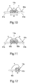
- Fig. 10 is a sectional view of a mating section of the conventional male contact taken along the direction perpendicular to the mating direction (cf. Japanese Toku-Kai-Hei 8 - 162191).
- a mating section 10a is formed in such a manner that both edge portions 51a and 51a extending in the mating direction of a sheet of plate member 50a represented by a broken line are folded (of. arrows a), so that both the edge portions 51a and 51a are confronted with one another at the center of the plate member 50a.
- Fig. 11 is a sectional view of a mating section of another conventional male contact taken along the direction perpendicular to the mating direction (cf. Japanese Toku-Kai-Hei 7 - 192793).
- a mating section 10b is formed in such a manner that both edge portions 51b and 51b extending in the mating direction of a sheet of plate member 50b represented by a broken line are wound (cf. arrows b), so that both the edge portions 51b and 51b are confronted with one another at the center of the plate member.
- the mating section 10b is different from the mating section 10a formed by folding of both the edge portions as shown in Fig. 10, and is provided with cavity sections 52b and 52b at both edges of the mating section 10b by winding.
- Fig. 12 is a sectional view of a mating section of further another conventional male contact taken along the direction perpendicular to the mating direction (cf. Japanese Toku-Kai-Hei 8 - 162191).
- a mating section 10c is formed in such a manner that a sheet of plate member 50c represented by a broken line is folded taking as a crease the center axis extending in the mating direction of the plate member 50c (cf. an arrow c), so that both edge portions of the plate member 50c are confronted with one another at one end of the plate member 50c and thereby forming a cavity 52c.
- Fig. 13 is a perspective view showing a state of a mating section of the conventional another male contact before the folding processing (cf. Japanese Toku-Kai-Hei 9 - 147947).
- a mating section formed at one end of a base 20d is formed in such a manner that a sheet of plate member 50d having a length twice the mating section extending along the mating direction is folded at the intermediate section 53d in a longitudinal direction of the plate member, which will be the top of the mating section, toward the side of the base 20d (cf. an arrow d).
- Fig. 14 shows another male contact disclosed by the above-mentioned Japanese Patent Publication Gazette.
- Part (a) of Fig. 14 is a perspective view showing a state of the mating section before bending processing of the mating section of the male contact.
- Part (b) of Fig. 14 is a perspective view showing a state of the mating section after the bending processing of the mating section of the male contact.
- a mating section 10e shown in the part (b) of Fig. 14 is formed by performing the bending processing for a sheet of plate member 50e shown in the part (a) of Fig. 14.
- the bending processing is performed in such a manner that both edge portions 51e and 51e, which extend in the mating direction from a base (not illustrated) to a top portion 54d of a plate member 50e, are folded (cf. arrows e1), and both the edge portions 51e and 51e are confronted with one another at the center of the plate member 50e, and the edge side of the top portion 54d of the plate member is folded to the base side not illustrated (of. an arrow e2).
- the mating section 10b formed by winding of both edge portions as shown in Fig. 11 has no flat portion on the top thereof, so that a contact area with an elastic contact segment of the female contact is small, and thus it is difficult to enhance a reliability of the electric contact.
- the mating section 10c formed by folding taking the center axis as a crease as shown in Fig. 12 is formed using a plate member having a plate thickness satisfying a desired strength, the narrower width w of the mating section, the more arc-like shape the folding side is concerned with.
- the present invention provides a male contact formed by folding a sheet of metallic plate, said male contact comprising a base and a mating section adapted to mate with a female contact, characterized in that said mating section is formed in such a manner that two sheets of plate members, which individually extend from said base, are superposed on one another by folding on said base; said two sheets of plate members superposed on one another have each a flat section extending in an mating direction and formed flat on an associated outer surface opposite to surfaces on which said two sheets of plate members are in contact with one another; and a tip of one of said two sheets of plate members is folded to overlap a tip of another.
- said mating section has a projecting section on one of said two sheets of plate members superposed on one another, said projecting section projecting toward another plate member, and a recess portion adapted to mate said projecting section with said another plate member.
- Fig. 1 is a perspective view of a male contact of an embodiment of the present invention.
- a male contact 1 is formed by bending processing of a sheet of metallic plate such as a copper alloy.
- the male contact 1 is provided with a mating section 10 at one end of a base 20, and a wire connecting section 30 at another end of the base 20.
- a plurality of male contacts 1 is coupled with a carrier 40 at another end of the wire connecting section 30, and is separated from the carrier 40 when the male contacts 1 are actually used.
- the wire connecting section 30 electrically connects wires (not illustrated).
- the mating section 10 mates with a female contact (not illustrated) in an mating direction P to electrically connect with an elastic contact section (not illustrated) of the female contact.
- the mating section 10 has two sheets of plate members 11 and 12 individually extending from the base 20. Those two sheets of plate members 11 and 12 are substantially the same as one anther in geometry excepting the tip and individually extend along the mating direction P.
- the mating section 10 is formed in such a manner that those two sheets of plate members 11 and 12 are folded on the base 20 to be superposed on one another. Thickness (0.64 mm in the present embodiment) of the mating section 10, which is the narrowest part of the parts of the male contact 1, is about a little longer than twice the plate thickness (0.25 mm in the present embodiment) of the plate member.
- a plurality of male contacts 1 is fixed on an insulating housing (not illustrated) and is used as an electrical connector.
- Fig. 2 is a left side elevation of the male contact of Fig. 1.
- Fig. 3 is a plan view of the male contact of Fig. 1.
- Fig. 4 is a right side elevation of the male contact of Fig. 1.
- Fig. 5 is a bottom view of the male contact of Fig, 1.
- Fig. 6 is a front view of the male contact of Fig. 1.
- Fig. 7 is a sectional view taken along the line A-A of Fig. 5.
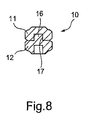
- Fig. 8 is a sectional view taken along the line B-B of Fig. 5.
- Fig. 9 is a sectional view taken along the line C-C of Fig. 3.
- a cross sectional size of the mating section 10 is 0.64 mm x 0.64 mm, and width of the flat section 15 is secured with about 0.3 mm.
- a tip 13 of the plate member 12 of the lower side is folded to overlap on a tip 14 of the plate member 11 of the upper side.
- This folding makes it possible to fix the plate members 11 and 12 on each other not so as to be separated in the vicinity of the tips.
- thickness of the plate members 11 and 12 is 0.25 mm.
- the tips 14 and 13 of the plate members 11 and 12 are formed thin by coining and the like, and those thinner sections 13 and 14 are superimposed each other, so that the plate thickness is formed within a desired value (according to the embodiment, 0.64 mm).
- shapes of the tips 13 and 14 of the plate members 11 and 12 are formed in such a way that when the plate members 12 and 11 are superimposed each other, the tips 13 and 14 are mutually out of place in the right and left of Fig.
- the tip 13 of the plate member 12 of the lower side is obliquely folded to the side of the plate member 11 of the upper side and the tip 14 of the plate member 11 of the upper side is obliquely folded to the side of the plate member 12 of the lower side, so that the tip of one of the plate members 11 and 12 is overlapped with the tip of another.
- a projecting portion 16 projecting toward the plate member 11 of the upper side.
- the plate member 11 of the upper side is provided with a recess portion 17, which mates with the projecting portion 16, in the vicinity of center of the plate member.
- the projecting portion 16 and the recess portion 17 are formed by press processing before superimposing two sheets of plate members 11 and 12, and are mated by superimposing those two sheets of plate members 11 and 12. Mating of the projecting portion 16 and the recess portion 17 may prevent the mutual deviation of the two sheets of plate members 11 and 12 in a horizontal direction perpendicular to the mating direction P (cf. Fig. 1).
- the base 20 has a lance 21 for fixing the male contact 1 on housing (not illustrated) and a stabilizer for stabilizing the posture of male contact 1 with in the housing.
- the wire connecting section 30 has an insulation barrel 31 for fixing a covering section (not illustrated) of a wire and a wire barrel 32 electrically connecting with a core of a wire.
- the insulation barrel 31 and the wire barrel 32 apply the covering section and the core wire respectively by a folding processing.
- the male contact 1 is fabricated with a metallic material having the lowest plate thickness satisfying a desired strength as a result of a strength computation.
- width and height of the mating section are defined by a standard and the like. According to the present embodiment, in order to provide the lowest plate thickness satisfying a desired strength for a plate thickness of the plate member and also satisfy conditions of width and height of the mating section defined, as shown in Fig.
- legs 18, 18, 18 and 18 obliquely standing with respect to the opposite direction to the associated plate member in the vicinity of both the edges extending along the respective mating direction P (cf. Fig. 1) of the two plate members 11 and 12.
- Slants 18_1, 18_1, 18_1 and 18_1, which incline toward the flat sections 15 and 15 side of the legs 18, are slants necessarily formed for forming the mating section 10 having thickness 0.64 mm using two plate members each having the plate thickness 0.25 mm according to the present embodiment.
- Slants 18_1, 18_1, 18_1 and 18_1 also function as planing off the corners of the edge portions extending along the mating direction P of the mating section 10.
- This feature makes it possible to prevent the female contact from being damaged at the time of mating. Further, as the legs 18, 18, 18 and 18 are formed, a cavity 19 is formed in the vicinity of the center axis of the mating section 10 extending the mating direction P so that the same effect as forming of beads on the plate members 11 and 12 is obtained. This feature makes it possible to enhance the mechanical strength of the mating section 10.
- the present invention is not restricted to the present embodiment, and can be modified within the spirit of the present invention as an occasion arises.
- the tip of the plate member 11 of the upper side is folded on the tip of the plate member 12 of the lower side.
- the plate member 11 of the upper side is provided with a projecting portion projecting toward the plate member 12 of the lower side, and the plate member 12 of the lower side is provided with a recess portion mating with the projecting portion.
- said male contact in the male contact formed by folding a sheet of metallic plate, said male contact comprising a base and a mating section adapted to mate with a female contact, said mating section is formed in such a manner that two sheets of plate members, which individually extend from said base, are superposed on one another by folding on said base; said two sheets of plate members superposed on one another have each a flat section extending in an mating direction and formed flat on an associated outer surface opposite to surfaces on which said two sheets of plate members are in contact with one another; and a tip of one of said two sheets of plate members is folded to overlap a tip of another.
- This feature makes it possible to provide a male contact which is high in reliability of an electric contact with the female contact and has a mating section capable of being formed with a compactness using a plate member having a plate thickness satisfying a desired strength, wherein the tips of the two sheets of plate members are hard to open.
- said mating section has a projecting section on one of said two sheets of plate members superposed on one another, said projecting section projecting toward another plate member, and a recess portion adapted to mate said projecting section with said another plate member.
Landscapes
- Coupling Device And Connection With Printed Circuit (AREA)
- Connector Housings Or Holding Contact Members (AREA)
Abstract
Description
- The present invention relates to a male contact formed by bending a sheet of metallic plate.
- There is well known, as shown in Fig. 10 to Fig. 14, a male contact having a mating section for mating with a female contact on one end of a base and a wire connecting section on another end of the base, the male contact being formed by punching processing and bending processing of a sheet of metallic plate.
- Fig. 10 is a sectional view of a mating section of the conventional male contact taken along the direction perpendicular to the mating direction (cf. Japanese Toku-Kai-Hei 8 - 162191). A
mating section 10a is formed in such a manner that bothedge portions plate member 50a represented by a broken line are folded (of. arrows a), so that both theedge portions plate member 50a. - Fig. 11 is a sectional view of a mating section of another conventional male contact taken along the direction perpendicular to the mating direction (cf. Japanese Toku-Kai-Hei 7 - 192793). A mating section 10b is formed in such a manner that both
edge portions plate member 50b represented by a broken line are wound (cf. arrows b), so that both theedge portions mating section 10a formed by folding of both the edge portions as shown in Fig. 10, and is provided withcavity sections - Fig. 12 is a sectional view of a mating section of further another conventional male contact taken along the direction perpendicular to the mating direction (cf. Japanese Toku-Kai-Hei 8 - 162191). A
mating section 10c is formed in such a manner that a sheet ofplate member 50c represented by a broken line is folded taking as a crease the center axis extending in the mating direction of theplate member 50c (cf. an arrow c), so that both edge portions of theplate member 50c are confronted with one another at one end of theplate member 50c and thereby forming acavity 52c. - Fig. 13 is a perspective view showing a state of a mating section of the conventional another male contact before the folding processing (cf. Japanese Toku-Kai-Hei 9 - 147947). A mating section formed at one end of a
base 20d is formed in such a manner that a sheet ofplate member 50d having a length twice the mating section extending along the mating direction is folded at theintermediate section 53d in a longitudinal direction of the plate member, which will be the top of the mating section, toward the side of thebase 20d (cf. an arrow d). - Fig. 14 shows another male contact disclosed by the above-mentioned Japanese Patent Publication Gazette. Part (a) of Fig. 14 is a perspective view showing a state of the mating section before bending processing of the mating section of the male contact. Part (b) of Fig. 14 is a perspective view showing a state of the mating section after the bending processing of the mating section of the male contact. A
mating section 10e shown in the part (b) of Fig. 14 is formed by performing the bending processing for a sheet ofplate member 50e shown in the part (a) of Fig. 14. The bending processing is performed in such a manner that bothedge portions top portion 54d of aplate member 50e, are folded (cf. arrows e1), and both theedge portions plate member 50e, and the edge side of thetop portion 54d of the plate member is folded to the base side not illustrated (of. an arrow e2). - Higher density of loading electric components needs compactness of male contacts. However, it is difficult to implement the compactness of mating sections having the conventional aspects as shown in Fig. 10 to Fig 14 with a plate member having a plate thickness satisfying a desired strength. Specifically, in the event that the
mating section 10a formed by folding of both the edges as shown in Fig. 10 is formed using a plate member having a plate thickness satisfying a desired strength, the narrower width w (cf. Fig 10) of the mating section, it is more difficult to perform folding both the edges. Even if processing for the folding of both the edges is carried out, a section of the mating section is easy to be a circle in its shape. This will cause a contact area with an elastic contact segment of the female contact to be small, and thus there is a possibility that a reliability of the electric contact is lowered. Further, the mating section 10b formed by winding of both edge portions as shown in Fig. 11 has no flat portion on the top thereof, so that a contact area with an elastic contact segment of the female contact is small, and thus it is difficult to enhance a reliability of the electric contact. In the event that themating section 10c formed by folding taking the center axis as a crease as shown in Fig. 12 is formed using a plate member having a plate thickness satisfying a desired strength, the narrower width w of the mating section, the more arc-like shape the folding side is concerned with. This will cause a contact area with an elastic contact segment of the female contact to be small, and thus it is difficult to enhance a reliability of the electric contact. In the event that the mating section formed by bending processing by folding to the base side as shown in Fig. 13 needs a plate member having twice length of the mating section extending along the mating direction. This involves a basic problem that the production efficiency is not so good and a yield rate of the materials is low, while the contact area is secured. Themating section 10e formed by folding of three points as shown in Fig. 14 is associated with a possibility that an elastic contact segment of the female contact is damaged by a seam on an upper surface of the mating section, as well as the basic problem that the production efficiency is inefficient. - In view of the foregoing, it is an object of the present invention to provide a male contact solving the above-mentioned problem, or a male contact which is high in reliability of an electric contact with the female contact and has a mating section capable of being formed with a compactness using a plate member having a plate thickness satisfying a desired strength.
- The present invention provides a male contact formed by folding a sheet of metallic plate, said male contact comprising a base and a mating section adapted to mate with a female contact, characterized in that said mating section is formed in such a manner that two sheets of plate members, which individually extend from said base, are superposed on one another by folding on said base; said two sheets of plate members superposed on one another have each a flat section extending in an mating direction and formed flat on an associated outer surface opposite to surfaces on which said two sheets of plate members are in contact with one another; and a tip of one of said two sheets of plate members is folded to overlap a tip of another.
- In the male contact according to the present invention as mentioned above, it is preferable that said mating section has a projecting section on one of said two sheets of plate members superposed on one another, said projecting section projecting toward another plate member, and a recess portion adapted to mate said projecting section with said another plate member.
-
- Fig. 1 is a perspective view of a male contact of an embodiment of the present invention.
- Fig. 2 is a left side elevation of the male contact of Fig. 1.
- Fig. 3 is a plan view of the male contact of Fig. 1.
- Fig. 4 is a right side elevation of the male contact of Fig. 1.
- Fig. 5 is a bottom view of the male contact of Fig. 1.
- Fig. 6 is a front view of the male contact of Fig. 1.
- Fig. 7 is a sectional view taken along the line A-A of Fig. 5.
- Fig. 8 is a sectional view taken along the line B-B of Fig. 5.
- Fig. 9 is a sectional view taken along the line C-C of Fig. 3.
- Fig. 10 is a sectional view of a mating section of the conventional male contact taken along the direction perpendicular to the mating direction.
- Fig. 11 is a sectional view of a mating section of another conventional male contact taken along the direction perpendicular to the mating direction.
- Fig. 12 is a sectional view of a mating section of further another conventional male contact taken along the direction perpendicular to the mating direction.
- Fig. 13 is a perspective view showing a state of a mating section of the conventional another male contact before the folding processing.
- Fig. 14 shows another conventional male contact. Part (a) of Fig. 14 is a perspective view showing a state of the mating section before bending processing of the mating section of the male contact. Part (b) of Fig. 14 is a perspective view showing a state of the mating section after the bending processing of the mating section of the male contact.
-
- Embodiments of the present invention will be described hereinafter. Fig. 1 is a perspective view of a male contact of an embodiment of the present invention. A
male contact 1 is formed by bending processing of a sheet of metallic plate such as a copper alloy. Themale contact 1 is provided with amating section 10 at one end of abase 20, and awire connecting section 30 at another end of thebase 20. A plurality ofmale contacts 1 is coupled with acarrier 40 at another end of thewire connecting section 30, and is separated from thecarrier 40 when themale contacts 1 are actually used. Thewire connecting section 30 electrically connects wires (not illustrated). Themating section 10 mates with a female contact (not illustrated) in an mating direction P to electrically connect with an elastic contact section (not illustrated) of the female contact. Themating section 10 has two sheets ofplate members base 20. Those two sheets ofplate members mating section 10 is formed in such a manner that those two sheets ofplate members mating section 10, which is the narrowest part of the parts of themale contact 1, is about a little longer than twice the plate thickness (0.25 mm in the present embodiment) of the plate member. Thus, it is possible to implement a compactness of the mating section using the plate member having a plate thickness satisfying a desired strength, and also it is easy in processing. A plurality ofmale contacts 1 is fixed on an insulating housing (not illustrated) and is used as an electrical connector. - Hereinafter, there will be explained the
male contact 1 using Fig. 2 to Fig. 9 taking themating section 10 as a leading part. Fig. 2 is a left side elevation of the male contact of Fig. 1. Fig. 3 is a plan view of the male contact of Fig. 1. Fig. 4 is a right side elevation of the male contact of Fig. 1. Fig. 5 is a bottom view of the male contact of Fig, 1. Fig. 6 is a front view of the male contact of Fig. 1. Fig. 7 is a sectional view taken along the line A-A of Fig. 5. Fig. 8 is a sectional view taken along the line B-B of Fig. 5. Fig. 9 is a sectional view taken along the line C-C of Fig. 3. - In Fig. 7, on the respective surfaces (outer surfaces) of two sheets of plate member opposite to the contacting surface of the mutually superposed two sheets of
plate members 11 and 2, that is, an upper surface 11_1 of theplate member 11 and a lower surface 12_1 of theplate member 12, there are providedflat portions flat portions mating section 10 is 0.64 mm x 0.64 mm, and width of theflat section 15 is secured with about 0.3 mm. - As shown in Fig. 2, a
tip 13 of theplate member 12 of the lower side is folded to overlap on atip 14 of theplate member 11 of the upper side. This folding makes it possible to fix theplate members plate members tip 13 of theplate member 12 of the lower side is simply folded on thetip 14 of theplate member 11 of the upper side, thickness of this folding section would become about 0.75 mm. For this reason, as apparent from Fig. 9, thetips plate members thinner sections tips plate members plate members tips tip 13 of theplate member 12 of the lower side is obliquely folded to the side of theplate member 11 of the upper side and thetip 14 of theplate member 11 of the upper side is obliquely folded to the side of theplate member 12 of the lower side, so that the tip of one of theplate members - As shown in Fig. 8 and Fig. 9, in the vicinity of the center of the
plate member 12 of the lower side of theplate members mating section 10. there is provided a projectingportion 16 projecting toward theplate member 11 of the upper side. Theplate member 11 of the upper side is provided with arecess portion 17, which mates with the projectingportion 16, in the vicinity of center of the plate member. The projectingportion 16 and therecess portion 17 are formed by press processing before superimposing two sheets ofplate members plate members portion 16 and therecess portion 17 may prevent the mutual deviation of the two sheets ofplate members - On the
male contact 1, there are additionally formed abase 20 and awire connecting section 30. As shown in Fig. 2, thebase 20 has alance 21 for fixing themale contact 1 on housing (not illustrated) and a stabilizer for stabilizing the posture ofmale contact 1 with in the housing. Thewire connecting section 30 has aninsulation barrel 31 for fixing a covering section (not illustrated) of a wire and awire barrel 32 electrically connecting with a core of a wire. Theinsulation barrel 31 and thewire barrel 32 apply the covering section and the core wire respectively by a folding processing. - Incidentally, according to the present embodiment, the thinner plate thickness of the
plate members male contact 1 becomes easier. Thus, themale contact 1 is fabricated with a metallic material having the lowest plate thickness satisfying a desired strength as a result of a strength computation. On the other hand, width and height of the mating section are defined by a standard and the like. According to the present embodiment, in order to provide the lowest plate thickness satisfying a desired strength for a plate thickness of the plate member and also satisfy conditions of width and height of the mating section defined, as shown in Fig. 7, there are providedlegs plate members flat sections legs 18, are slants necessarily formed for forming themating section 10 having thickness 0.64 mm using two plate members each having the plate thickness 0.25 mm according to the present embodiment. Slants 18_1, 18_1, 18_1 and 18_1 also function as planing off the corners of the edge portions extending along the mating direction P of themating section 10. This feature makes it possible to prevent the female contact from being damaged at the time of mating. Further, as thelegs cavity 19 is formed in the vicinity of the center axis of themating section 10 extending the mating direction P so that the same effect as forming of beads on theplate members mating section 10. - While the above explanation is made for the preferred embodiment of the present invention, the present invention is not restricted to the present embodiment, and can be modified within the spirit of the present invention as an occasion arises. For example, it is acceptable that the tip of the
plate member 11 of the upper side is folded on the tip of theplate member 12 of the lower side. Alternatively, it is acceptable that theplate member 11 of the upper side is provided with a projecting portion projecting toward theplate member 12 of the lower side, and theplate member 12 of the lower side is provided with a recess portion mating with the projecting portion. - According to the male contact disclosed in
claim 1, in the male contact formed by folding a sheet of metallic plate, said male contact comprising a base and a mating section adapted to mate with a female contact, said mating section is formed in such a manner that two sheets of plate members, which individually extend from said base, are superposed on one another by folding on said base; said two sheets of plate members superposed on one another have each a flat section extending in an mating direction and formed flat on an associated outer surface opposite to surfaces on which said two sheets of plate members are in contact with one another; and a tip of one of said two sheets of plate members is folded to overlap a tip of another. This feature makes it possible to provide a male contact which is high in reliability of an electric contact with the female contact and has a mating section capable of being formed with a compactness using a plate member having a plate thickness satisfying a desired strength, wherein the tips of the two sheets of plate members are hard to open. - Further, according to the male contact disclosed in claim 2, said mating section has a projecting section on one of said two sheets of plate members superposed on one another, said projecting section projecting toward another plate member, and a recess portion adapted to mate said projecting section with said another plate member. This feature makes it possible to prevent the mutual deviation of the two sheets of plate members in a horizontal direction perpendicular to the mating direction.
Claims (2)
- A male contact formed by folding a sheet of metallic plate, said male contact comprising a base and a mating section adapted to mate with a female contact,
wherein said mating section is formed in such a manner that two sheets of plate members, which individually extend from said base, are superposed on one another by folding on said base.
said two sheets of plate members superposed on one another have each a flat section extending in an mating direction and formed flat on an associated outer surface opposite to surfaces on which said two sheets of plate members are in contact with one another, and
a tip of one of said two sheets of plate members is folded to overlap a tip of another. - A male contact according to claim 1, wherein said mating section has a projecting section on one of said two sheets of plate members superposed on one another, said projecting section projecting toward another plate member, and a recess portion adapted to mate said projecting section with said another plate member.
Applications Claiming Priority (3)
| Application Number | Priority Date | Filing Date | Title |
|---|---|---|---|
| JP2000203541 | 2000-07-05 | ||
| JP2000203541 | 2000-07-05 | ||
| PCT/JP2001/005841 WO2002003504A1 (en) | 2000-07-05 | 2001-07-05 | Male contact |
Publications (3)
| Publication Number | Publication Date |
|---|---|
| EP1306929A1 true EP1306929A1 (en) | 2003-05-02 |
| EP1306929A4 EP1306929A4 (en) | 2006-04-05 |
| EP1306929B1 EP1306929B1 (en) | 2009-03-04 |
Family
ID=18700934
Family Applications (1)
| Application Number | Title | Priority Date | Filing Date |
|---|---|---|---|
| EP01947847A Expired - Lifetime EP1306929B1 (en) | 2000-07-05 | 2001-07-05 | Male contact |
Country Status (5)
| Country | Link |
|---|---|
| US (1) | US6786781B2 (en) |
| EP (1) | EP1306929B1 (en) |
| JP (1) | JP4614619B2 (en) |
| DE (1) | DE60137851D1 (en) |
| WO (1) | WO2002003504A1 (en) |
Cited By (5)
| Publication number | Priority date | Publication date | Assignee | Title |
|---|---|---|---|---|
| EP1703600A1 (en) * | 2005-03-17 | 2006-09-20 | Sumitomo Wiring Systems, Ltd. | Chained terminals and method of forming chained terminals |
| EP1526608A3 (en) * | 2003-10-22 | 2008-05-21 | Yazaki Europe Ltd. | Electrical contact element |
| WO2014083179A1 (en) * | 2012-11-30 | 2014-06-05 | Tyco Electronics Amp Gmbh | Contact housing for an electrical connector element and connector element |
| WO2014090422A1 (en) * | 2012-12-13 | 2014-06-19 | Tyco Electronics Amp Gmbh | Contact element and method for producing a contact element |
| WO2015039844A1 (en) * | 2013-09-23 | 2015-03-26 | Phoenix Contact Gmbh & Co. Kg | Cable lug device having a current bar, and connection terminal |
Families Citing this family (6)
| Publication number | Priority date | Publication date | Assignee | Title |
|---|---|---|---|---|
| TW200501521A (en) * | 2003-04-16 | 2005-01-01 | J S T Mfg Co Ltd | Electric coupler and housing of plug-type connector |
| US7104812B1 (en) * | 2005-02-24 | 2006-09-12 | Molex Incorporated | Laminated electrical terminal |
| JP5008492B2 (en) * | 2007-08-01 | 2012-08-22 | 株式会社オートネットワーク技術研究所 | Shield connector |
| JP6193122B2 (en) * | 2010-08-20 | 2017-09-06 | デルフィ・インターナショナル・オペレーションズ・ルクセンブルク・エス・アー・エール・エル | Male electrical terminal |
| JP6536898B2 (en) * | 2015-12-11 | 2019-07-03 | 住友電装株式会社 | Terminal bracket |
| TWI721615B (en) | 2019-10-24 | 2021-03-11 | 大陸商東莞訊滔電子有限公司 | Electrical connector thereof |
Family Cites Families (10)
| Publication number | Priority date | Publication date | Assignee | Title |
|---|---|---|---|---|
| DE4200109A1 (en) | 1992-01-04 | 1993-07-08 | Daut & Rietz Trw | KNIFE CONTACT FOR ELECTRICAL CONNECTORS |
| NL9200118A (en) | 1992-01-22 | 1993-08-16 | Du Pont Nederland | ELECTRICAL CONNECTOR WITH PLATE MATERIAL CONNECTORS. |
| JPH0734563A (en) | 1993-07-22 | 1995-02-03 | Misawa Homes Co Ltd | Composite exterior panel |
| JPH0734563U (en) * | 1993-12-08 | 1995-06-23 | 住友電装株式会社 | Male terminal fitting |
| JPH07192793A (en) | 1993-12-28 | 1995-07-28 | Yazaki Corp | Terminal structure |
| JP3046731B2 (en) | 1994-11-30 | 2000-05-29 | 矢崎総業株式会社 | Male terminal and method of manufacturing male terminal |
| JP3202561B2 (en) | 1995-11-17 | 2001-08-27 | 矢崎総業株式会社 | Male terminal fitting |
| JP3177144B2 (en) * | 1996-02-14 | 2001-06-18 | 矢崎総業株式会社 | Male terminal |
| JP3478022B2 (en) | 1996-10-17 | 2003-12-10 | 住友電装株式会社 | Male terminal fitting |
| JP3316198B2 (en) | 1999-10-29 | 2002-08-19 | タイコエレクトロニクスアンプ株式会社 | Male contact |
-
2001
- 2001-07-05 JP JP2002507477A patent/JP4614619B2/en not_active Expired - Fee Related
- 2001-07-05 EP EP01947847A patent/EP1306929B1/en not_active Expired - Lifetime
- 2001-07-05 US US10/332,090 patent/US6786781B2/en not_active Expired - Lifetime
- 2001-07-05 WO PCT/JP2001/005841 patent/WO2002003504A1/en not_active Ceased
- 2001-07-05 DE DE60137851T patent/DE60137851D1/en not_active Expired - Lifetime
Non-Patent Citations (2)
| Title |
|---|
| No further relevant documents disclosed * |
| See also references of WO0203504A1 * |
Cited By (8)
| Publication number | Priority date | Publication date | Assignee | Title |
|---|---|---|---|---|
| EP1526608A3 (en) * | 2003-10-22 | 2008-05-21 | Yazaki Europe Ltd. | Electrical contact element |
| EP1703600A1 (en) * | 2005-03-17 | 2006-09-20 | Sumitomo Wiring Systems, Ltd. | Chained terminals and method of forming chained terminals |
| WO2014083179A1 (en) * | 2012-11-30 | 2014-06-05 | Tyco Electronics Amp Gmbh | Contact housing for an electrical connector element and connector element |
| WO2014090422A1 (en) * | 2012-12-13 | 2014-06-19 | Tyco Electronics Amp Gmbh | Contact element and method for producing a contact element |
| CN104981945A (en) * | 2012-12-13 | 2015-10-14 | 泰科电子Amp有限责任公司 | Contact element and method of manufacturing contact element |
| CN104981945B (en) * | 2012-12-13 | 2018-02-09 | 泰连德国有限公司 | Contact element and method of manufacturing contact element |
| WO2015039844A1 (en) * | 2013-09-23 | 2015-03-26 | Phoenix Contact Gmbh & Co. Kg | Cable lug device having a current bar, and connection terminal |
| CN105580203A (en) * | 2013-09-23 | 2016-05-11 | 菲尼克斯电气公司 | Cable lug device having current bar, and connection terminal |
Also Published As
| Publication number | Publication date |
|---|---|
| EP1306929A4 (en) | 2006-04-05 |
| DE60137851D1 (en) | 2009-04-16 |
| US6786781B2 (en) | 2004-09-07 |
| WO2002003504A1 (en) | 2002-01-10 |
| EP1306929B1 (en) | 2009-03-04 |
| US20030119383A1 (en) | 2003-06-26 |
| JP4614619B2 (en) | 2011-01-19 |
Similar Documents
| Publication | Publication Date | Title |
|---|---|---|
| US5664974A (en) | Male terminal and method of manufacturing thereof | |
| CN101645544B (en) | A terminal fitting and a method of forming it | |
| JP4372138B2 (en) | Electrical contact | |
| US6077131A (en) | Male terminal | |
| EP1306929B1 (en) | Male contact | |
| US7553203B2 (en) | Connecting terminal | |
| JP2003157920A (en) | Male side tub | |
| CN109616808B (en) | High-current electric connector | |
| EP0569064B1 (en) | Electrical sleeve terminal | |
| JPH0945404A (en) | Female terminal | |
| JP2003036911A (en) | Male terminal fitting | |
| US6790106B2 (en) | Male terminal fitting and method of forming it | |
| JP2017147095A (en) | Female terminal and method for manufacturing female terminal | |
| JP2003217711A (en) | Connector | |
| EP1526613A1 (en) | Male bar-like connection terminal, and method of producing the same | |
| JPH07192793A (en) | Terminal structure | |
| JPWO2002003504A1 (en) | Male Contact | |
| JP3316198B2 (en) | Male contact | |
| JPH0883636A (en) | Female terminal metal | |
| US6416366B2 (en) | Terminal metal fitting | |
| JPH11144789A (en) | Terminal structure | |
| JP7435362B2 (en) | Terminal fittings and chain terminals | |
| EP2575215B1 (en) | Terminal fitting | |
| JP7114053B2 (en) | female terminal | |
| JP2008066271A (en) | Terminal original plate, continuous terminal, manufacturing method of terminal original plate, manufacturing method of continuous terminal, and manufacturing method of electric wire with terminal |
Legal Events
| Date | Code | Title | Description |
|---|---|---|---|
| PUAI | Public reference made under article 153(3) epc to a published international application that has entered the european phase |
Free format text: ORIGINAL CODE: 0009012 |
|
| 17P | Request for examination filed |
Effective date: 20030117 |
|
| AK | Designated contracting states |
Designated state(s): DE FR GB |
|
| A4 | Supplementary search report drawn up and despatched |
Effective date: 20060217 |
|
| 17Q | First examination report despatched |
Effective date: 20080131 |
|
| GRAP | Despatch of communication of intention to grant a patent |
Free format text: ORIGINAL CODE: EPIDOSNIGR1 |
|
| GRAS | Grant fee paid |
Free format text: ORIGINAL CODE: EPIDOSNIGR3 |
|
| GRAA | (expected) grant |
Free format text: ORIGINAL CODE: 0009210 |
|
| AK | Designated contracting states |
Kind code of ref document: B1 Designated state(s): DE FR GB |
|
| REG | Reference to a national code |
Ref country code: GB Ref legal event code: FG4D |
|
| REF | Corresponds to: |
Ref document number: 60137851 Country of ref document: DE Date of ref document: 20090416 Kind code of ref document: P |
|
| PGFP | Annual fee paid to national office [announced via postgrant information from national office to epo] |
Ref country code: FR Payment date: 20090717 Year of fee payment: 9 |
|
| PLBE | No opposition filed within time limit |
Free format text: ORIGINAL CODE: 0009261 |
|
| STAA | Information on the status of an ep patent application or granted ep patent |
Free format text: STATUS: NO OPPOSITION FILED WITHIN TIME LIMIT |
|
| 26N | No opposition filed |
Effective date: 20091207 |
|
| REG | Reference to a national code |
Ref country code: GB Ref legal event code: 746 Effective date: 20100423 |
|
| REG | Reference to a national code |
Ref country code: FR Ref legal event code: CD |
|
| REG | Reference to a national code |
Ref country code: FR Ref legal event code: ST Effective date: 20110331 |
|
| PG25 | Lapsed in a contracting state [announced via postgrant information from national office to epo] |
Ref country code: FR Free format text: LAPSE BECAUSE OF NON-PAYMENT OF DUE FEES Effective date: 20100802 |
|
| PGFP | Annual fee paid to national office [announced via postgrant information from national office to epo] |
Ref country code: GB Payment date: 20200624 Year of fee payment: 20 |
|
| PGFP | Annual fee paid to national office [announced via postgrant information from national office to epo] |
Ref country code: DE Payment date: 20200624 Year of fee payment: 20 |
|
| REG | Reference to a national code |
Ref country code: DE Ref legal event code: R071 Ref document number: 60137851 Country of ref document: DE |
|
| REG | Reference to a national code |
Ref country code: GB Ref legal event code: PE20 Expiry date: 20210704 |
|
| PG25 | Lapsed in a contracting state [announced via postgrant information from national office to epo] |
Ref country code: GB Free format text: LAPSE BECAUSE OF EXPIRATION OF PROTECTION Effective date: 20210704 |