EP1306921A2 - Antenna apparatus for folder type mobile phone - Google Patents

Antenna apparatus for folder type mobile phone Download PDF

Info

Publication number
EP1306921A2
EP1306921A2 EP02024463A EP02024463A EP1306921A2 EP 1306921 A2 EP1306921 A2 EP 1306921A2 EP 02024463 A EP02024463 A EP 02024463A EP 02024463 A EP02024463 A EP 02024463A EP 1306921 A2 EP1306921 A2 EP 1306921A2
Authority
EP
European Patent Office
Prior art keywords
antenna
folder
mobile phone
main body
antenna apparatus
Prior art date
Legal status (The legal status is an assumption and is not a legal conclusion. Google has not performed a legal analysis and makes no representation as to the accuracy of the status listed.)
Ceased
Application number
EP02024463A
Other languages
German (de)
French (fr)
Other versions
EP1306921A3 (en
Inventor
Kyung-Wook Kim
Jin-Woo Park
Juh-Hyung Lee
Dong-In Ha
Krylov Konstantine
Jong-Kui Park
Byung-Man Lim
Jung-Ho Park
Sun-Kyung Kim
Joon-Ho Byun
Wan-Jin Choi
Dong-Hwan Kim
Current Assignee (The listed assignees may be inaccurate. Google has not performed a legal analysis and makes no representation or warranty as to the accuracy of the list.)
Samsung Electronics Co Ltd
Original Assignee
Samsung Electronics Co Ltd
Priority date (The priority date is an assumption and is not a legal conclusion. Google has not performed a legal analysis and makes no representation as to the accuracy of the date listed.)
Filing date
Publication date
Priority claimed from KR10-2002-0024932A external-priority patent/KR100480250B1/en
Application filed by Samsung Electronics Co Ltd filed Critical Samsung Electronics Co Ltd
Publication of EP1306921A2 publication Critical patent/EP1306921A2/en
Publication of EP1306921A3 publication Critical patent/EP1306921A3/en
Ceased legal-status Critical Current

Links

Images

Classifications

    • HELECTRICITY
    • H04ELECTRIC COMMUNICATION TECHNIQUE
    • H04MTELEPHONIC COMMUNICATION
    • H04M1/00Substation equipment, e.g. for use by subscribers
    • H04M1/02Constructional features of telephone sets
    • H04M1/0202Portable telephone sets, e.g. cordless phones, mobile phones or bar type handsets
    • H04M1/0206Portable telephones comprising a plurality of mechanically joined movable body parts, e.g. hinged housings
    • H04M1/0241Portable telephones comprising a plurality of mechanically joined movable body parts, e.g. hinged housings using relative motion of the body parts to change the operational status of the telephone set, e.g. switching on/off, answering incoming call
    • H04M1/0245Portable telephones comprising a plurality of mechanically joined movable body parts, e.g. hinged housings using relative motion of the body parts to change the operational status of the telephone set, e.g. switching on/off, answering incoming call using open/close detection
    • HELECTRICITY
    • H01ELECTRIC ELEMENTS
    • H01QANTENNAS, i.e. RADIO AERIALS
    • H01Q1/00Details of, or arrangements associated with, antennas
    • H01Q1/12Supports; Mounting means
    • H01Q1/22Supports; Mounting means by structural association with other equipment or articles
    • H01Q1/24Supports; Mounting means by structural association with other equipment or articles with receiving set
    • H01Q1/241Supports; Mounting means by structural association with other equipment or articles with receiving set used in mobile communications, e.g. GSM
    • H01Q1/242Supports; Mounting means by structural association with other equipment or articles with receiving set used in mobile communications, e.g. GSM specially adapted for hand-held use
    • HELECTRICITY
    • H01ELECTRIC ELEMENTS
    • H01QANTENNAS, i.e. RADIO AERIALS
    • H01Q1/00Details of, or arrangements associated with, antennas
    • H01Q1/12Supports; Mounting means
    • H01Q1/22Supports; Mounting means by structural association with other equipment or articles
    • H01Q1/24Supports; Mounting means by structural association with other equipment or articles with receiving set
    • H01Q1/241Supports; Mounting means by structural association with other equipment or articles with receiving set used in mobile communications, e.g. GSM
    • H01Q1/242Supports; Mounting means by structural association with other equipment or articles with receiving set used in mobile communications, e.g. GSM specially adapted for hand-held use
    • H01Q1/243Supports; Mounting means by structural association with other equipment or articles with receiving set used in mobile communications, e.g. GSM specially adapted for hand-held use with built-in antennas
    • HELECTRICITY
    • H01ELECTRIC ELEMENTS
    • H01QANTENNAS, i.e. RADIO AERIALS
    • H01Q1/00Details of, or arrangements associated with, antennas
    • H01Q1/12Supports; Mounting means
    • H01Q1/22Supports; Mounting means by structural association with other equipment or articles
    • H01Q1/24Supports; Mounting means by structural association with other equipment or articles with receiving set
    • H01Q1/241Supports; Mounting means by structural association with other equipment or articles with receiving set used in mobile communications, e.g. GSM
    • H01Q1/242Supports; Mounting means by structural association with other equipment or articles with receiving set used in mobile communications, e.g. GSM specially adapted for hand-held use
    • H01Q1/243Supports; Mounting means by structural association with other equipment or articles with receiving set used in mobile communications, e.g. GSM specially adapted for hand-held use with built-in antennas
    • H01Q1/244Supports; Mounting means by structural association with other equipment or articles with receiving set used in mobile communications, e.g. GSM specially adapted for hand-held use with built-in antennas extendable from a housing along a given path
    • HELECTRICITY
    • H01ELECTRIC ELEMENTS
    • H01QANTENNAS, i.e. RADIO AERIALS
    • H01Q1/00Details of, or arrangements associated with, antennas
    • H01Q1/36Structural form of radiating elements, e.g. cone, spiral, umbrella; Particular materials used therewith
    • HELECTRICITY
    • H01ELECTRIC ELEMENTS
    • H01QANTENNAS, i.e. RADIO AERIALS
    • H01Q21/00Antenna arrays or systems
    • H01Q21/30Combinations of separate antenna units operating in different wavebands and connected to a common feeder system
    • HELECTRICITY
    • H04ELECTRIC COMMUNICATION TECHNIQUE
    • H04BTRANSMISSION
    • H04B7/00Radio transmission systems, i.e. using radiation field
    • H04B7/02Diversity systems; Multi-antenna system, i.e. transmission or reception using multiple antennas
    • H04B7/04Diversity systems; Multi-antenna system, i.e. transmission or reception using multiple antennas using two or more spaced independent antennas
    • H04B7/08Diversity systems; Multi-antenna system, i.e. transmission or reception using multiple antennas using two or more spaced independent antennas at the receiving station
    • H04B7/0802Diversity systems; Multi-antenna system, i.e. transmission or reception using multiple antennas using two or more spaced independent antennas at the receiving station using antenna selection
    • H04B7/0805Diversity systems; Multi-antenna system, i.e. transmission or reception using multiple antennas using two or more spaced independent antennas at the receiving station using antenna selection with single receiver and antenna switching
    • HELECTRICITY
    • H04ELECTRIC COMMUNICATION TECHNIQUE
    • H04MTELEPHONIC COMMUNICATION
    • H04M1/00Substation equipment, e.g. for use by subscribers
    • H04M1/02Constructional features of telephone sets
    • H04M1/0202Portable telephone sets, e.g. cordless phones, mobile phones or bar type handsets
    • H04M1/0206Portable telephones comprising a plurality of mechanically joined movable body parts, e.g. hinged housings
    • H04M1/0208Portable telephones comprising a plurality of mechanically joined movable body parts, e.g. hinged housings characterized by the relative motions of the body parts
    • H04M1/0214Foldable telephones, i.e. with body parts pivoting to an open position around an axis parallel to the plane they define in closed position

Definitions

  • the present invention relates generally to a folder type mobile phone, and more particularly, to an antenna apparatus for a folder type mobile phone.
  • Mobile phones have become increasingly developed, aiming for the smaller size, lighter weight, multi functions, and lower power consumption.
  • An antenna one of essential components of the mobile phone, is a crucial factor for determining speech quality.
  • a typically used antenna for the mobile phone is a combination of a helical antenna and a whip antenna, as illustrated in FIG. 1.
  • a helical antenna When the mobile phone is in signal waiting state or the mobile phone's radio environment is favorable, only the helical antenna operates. On the other hand, when the mobile phone is used for conversation or the mobile phone's radio environment is poor, both the helical antenna and the whip antenna are operational.
  • an antenna is an electronic combination of a helical antenna and a whip antenna.
  • the helical antenna has a relatively large volume and is generally affixed on the top end of the mobile phone.
  • the whip antenna's signals can be supplied or not.
  • the folder type mobile phone is more popular among people.
  • the folder type mobile phone is illustrated in FIG. 2 and FIG. 3.
  • the folder type mobile phone includes a main body 100, a folder 200, and a hinge that connects the main body 100 to the folder 200 in a manner that they can rotate.
  • the hinge acts as an opening/closing means for the folder 200 because the folder 200 rotates around a hinge shaft.
  • the main body 100 of the folder type mobile phone includes an antenna apparatus 110 for extending or withdrawing toward the arrow direction on one side of the top end, a keypad 112 comprising a plurality of keys, and a transmitting block 114 with a built-in microphone at the lower side of the keypad 112.
  • the main body 100 includes a side hinge arm 101 for attaching to the folder 200.
  • the folder 200 includes a receiving block 210 with a built-in speaker apparatus on the top end, a LCD (Liquid Crystal Display) module 212 disposed at a lower side of the receiving block 210, and a center hinge arm 201 for combining to the side hinge arm 101.
  • LCD Liquid Crystal Display
  • the main body 100 in addition to the antenna apparatus 110, can further include a diversity antenna 111. That is, through combining signals that are received to these two antennas 110 and 111, respectively, optimal signals are detected, thereby preventing the fading phenomenon and getting better quality signals. As the diversity antenna 111 is more distant from the antenna apparatus 110, the aforementioned effect is improved.
  • the antenna of the folder type mobile phone is that because the antenna is projected from a designated position of the main body, it is inconvenient to carry around the mobile phone. In addition, if a user drops the mobile phone, the antenna is easily damaged. Again, since the antenna is projected from the main body, designing the antenna itself is a difficult task. Unfortunately, all these problems are enhanced by applying the second diversity antenna to the microphone. Likewise, it is difficult to secure sufficient separation distance between the main antenna apparatus and the diversity antenna.
  • an object of the present invention to provide an antenna apparatus for a folder type mobile phone, which is easy to carry and is capable of preventing damage on the antenna.
  • Another object of the present invention is to provide an antenna apparatus for a folder type mobile phone, which is capable of securing sufficient separation distance between a main antenna apparatus and a diversity antenna.
  • an antenna apparatus for a folder type mobile phone in which the mobile phone opens/closes as a folder thereof rotates by a hinge apparatus connecting a main body to the folder, the antenna apparatus including: a first antenna, which is built in one side of the main body extending in a longitudinal direction, and operates when the folder of the mobile phone is open or closed; a second antenna, which is built in the same side of the folder extending in a longitudinal direction, and operates when the folder of the mobile phone is open; and a connecting block, which forms a contact point for connecting the top end of the first antenna to the bottom end of the second antenna.
  • an antenna apparatus for a folder type mobile phone mounted with a receiving block to prevent a fading phenomenon wherein the folder type mobile phone opens/closes as a folder thereof rotates by a hinge apparatus connecting a main body to the folder
  • the antenna apparatus including: a first antenna connected to a transceiving block of the mobile phone, which is built in one side of the main body extending in a longitudinal direction and operates when the folder of the mobile phone is open or closed; a second antenna connectable to the receiving block, which is built in a different side of the folder extending in a longitudinal direction and separated from the first antenna by a designated distance, and operates when the folder of the mobile phone is open; and a connecting block, which forms a contact point for connecting the bottom end of the second antenna to the receiving block as the folder of the mobile phone is open.
  • Still another preferred embodiment of the present invention provides an antenna apparatus for a folder type mobile phone, in which the mobile phone opens/closes as a folder thereof rotates by a hinge apparatus connecting a main body to the folder, the antenna apparatus including: a first antenna, which is formed by combining a helical antenna with a whip antenna, being projected from one side of top end of the main body; and a second antenna, which is built in a different side of the folder extending in a longitudinal direction, and is electrically connected to a main board of the mobile phone.
  • FIG. 4 is an explanatory block diagram of a mobile phone antenna apparatus in accordance with a first preferred embodiment of the present invention.
  • the antenna apparatus for a folder type mobile phone includes a first antenna 2, a second antenna 4, a connecting block 6, a duplexer 8, and a transceiving block 10.
  • the first antenna 2 outputs receiving signals from a base station to the transceiving block 10 via the duplexer 8, and sends transmitting signals that are outputted from the transceiving block 10 via the duplexer 8 to the base station.
  • the first antenna 2 is constructed in such manner that it works even when the folder of the mobile phone is closed, that is, the first antenna operates when the phone is in a call waiting state and also during conversation.
  • the second antenna 4 performs the same function as the first antenna 2, except that the second antenna 4 does not operate when the folder is closed because it is connected to the first antenna 2 through the connecting block 6 only when the folder of the mobile phone is open.
  • FIG. 5 is a diagram showing a closed folder type mobile phone, to which the mobile phone antenna apparatus shown in FIG. 4 is applied
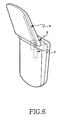
  • FIG. 6 is a diagram showing the folder type mobile phone of FIG. 5 in an open position.
  • the first antenna 2 is built in one side of the main body of the mobile phone extending ina longitudinal direction
  • the second antenna 4 is built in the same side of the folder extending in a longitudinal direction.
  • the first antenna 2 and the second antenna 4 are installed in corresponding positions so that their top end portions as shown in FIG. 5 are electrically connectable when the folder is open as shown in FIG. 6.
  • a whip antenna may be used
  • the second antenna 4 a helical antenna may be used.
  • other kinds of antennas may be applied as well.
  • the connecting block 6 for connecting the first antenna 2 to the second antenna 4 is disposed at the top end of the main body, and comprises a contact point made of metal. In other words, the connecting block 6 connects the first antenna 2 with the second antenna 4 when the folder is open, so these two antennas 2 and 4 operate together.
  • antenna apparatus may be applied to a folder type mobile telephone that, besides the transceiving block, further includes a receiving block to prevent a fading phenomenon, in short, to a folder type mobile phone based on a diversity receiving mode.
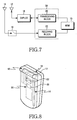
  • FIG. 7 is an explanatory block diagram of a mobile phone antenna apparatus in accordance with a second preferred embodiment of the present invention.
  • the antenna apparatus for a folder type mobile phone includes a first antenna 12, a second antenna 14, a connecting block 16, a duplexer 18, a transceiving block 20, and a receiving block 22.
  • the first antenna 12 outputs received signals from a base station to the transceiving block 20 via the duplexer 18, and sends transmitting signals that are outputted from the transceiving block 20 via the duplexer 18 to the base station.
  • the first antenna 12 operates even when the folder of the mobile phone is closed, that is, the first antenna 12 works not only when the mobile phone is in the call waiting state and but also during conversation.
  • the second antenna 14 outputs receiving signals from the base station to the received block 22. If the folder type mobile phone is open, the second antenna 14 is connected to the receiving block 22 by the connecting block 16 and works simultaneously with the first antenna 12 during the voice call or when text and image data is transceived. Data such as the voice call, the text or the image data are transmitted to the first antenna 12 through MSM chip 70 performing modem function and the transceiving block 20, and the received data are inputted to the MSM chip 70 through the transceiving block 20 and the receiving block 22.
  • FIG. 8 is a diagram showing a closed folder type mobile phone, to which the mobile phone antenna apparatus shown in FIG. 7 is applied
  • FIG. 9 is a diagram showing the folder type mobile phone of FIG. 8 in on open position.
  • the first antenna 12 is built in at one side of the main body extending in a longitudinal direction, and is connected to the transceiving block 20 of the folder type mobile phone.
  • Second antenna 14 is built in an opposite side of the folder extending in a longitudinal direction, and is connectable to the receiving block 22 of the folder type mobile phone.
  • the first antenna 12 and the second antenna 14 are built in at different positions from each other, and more preferably, to get an optical diversity effect, they are disposed in a way to secure a maximum separation distance within the mobile phone.
  • the connecting block 16 that connects the second antenna 14 with the receiving block 22 comprises a metallic contact disposed at the top end of the main body, that is electrical connected to the receiving block 22 included in a main board 30 of the folder type mobile phone.
  • the connecting block 16 that connects the second antenna 14 with the receiving block 22 comprises a metallic contact disposed at the top end of the main body, that is electrical connected to the receiving block 22 included in a main board 30 of the folder type mobile phone.
  • an end of the second antenna 14 contacts the metallic contact, thus connecting second antenna 14 with the receiving block 22 in the main board of the mobile phone. Therefore the first antenna 12 and the second antenna 14 operate, respectively, during the conversation.
  • the second antenna which is connected to the receiving block 22 by the connecting block 16, operates together with the first antenna 12.
  • FIG. 10 is an explanatory block diagram of a mobile phone antenna apparatus in accordance with a third preferred embodiment of the present invention.
  • the drawing illustrates the antenna apparatus for a mobile phone according to the second preferred embodiment of the present invention to which the antenna apparatus based on the diversity receiving mode is applied.
  • the antenna apparatus in such case includes a first antenna 32, a second antenna 34, a duplexer 38, a transceiving block 40, and a receiving block 36.
  • the first antenna 32 outputs received signals from a base station to the transceiving block 40 via the duplexer 38, and sends transmitted signals that are outputted from the transceiving block 40 via the duplexer 38 to the base station.
  • the second antenna 34 outputs received signals from the base station to the receiving block 36.
  • FIG. 11 is a diagram showing an open folder type mobile phone to which the mobile phone antenna apparatus shown in FIG. 10 is applied.
  • the first antenna 32 is projected from one side of the main body of the folder type mobile phone, and can be a combination of a helical antenna with a whip antenna.
  • Second antenna 34a is built in the folder of the folder type mobile phone.
  • the second antenna 34a may be implemented by forming an antenna pattern on a flexible print circuit substrate 50b mounted in the folder, or on the inner wall of a housing of the folder, or the second antenna 34a may be implemented by installing a small helical antenna.
  • the second antenna 34a is located in a place where the separation distance from the first antenna 32 is at its maximum. In case the first and the second antennas are mounted in the main body In case that the second antenna is built in the folder Separation distance 4cm and below 6cm and above Isolation -10dB ⁇ -6dB -20dB and above
  • each antenna's ground is separated from each other, and more separation distance can be secured. Therefore, it is shown that the isolation characteristic, i.e., deterioration of an antenna gain caused by mutual interference of adjacent antennas in the antenna apparatus based on the diversity receiving mode, is much improved.
  • a fixed wire connection 34b is shown for connecting the second antenna 34a with the main board 50a, and forms the connecting block of the prior embodiment.
  • a flexible print circuit substrate 50b mounted in and the folder a flexible print circuit or radio frequency coaxial cable can be used.
  • the first antenna 32 and the second antenna 34 operate all the time regardless of whether the mobile phone is in the busy state or call waiting state.
  • the separation distance between the first antenna 32 and the second antenna 34 is at its maximum when the mobile phone is in the busy state (i.e., the folder is open). Therefore, it is possible to reduce the drop rate and to enhance speed quality by increasing the diversity effect and by improving the isolation characteristic.
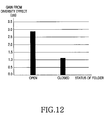
  • FIG. 12 diagrammatically represents an antenna gain by a diversity effect of the first antenna 32 and the second antenna 34.
  • the diversity effect resulted in better antenna gains, for example, when the folder is open, the antenna gain was increased by 2.5dB to 3.0dB, and when the folder is closed, the antenna gain was increased by 1.0dB to 1.5dB.
  • the antenna apparatus for a folder type mobile phone embodying the principles of the present invention has an antenna built in the main body and the folder, so it became much more convenient to carry the folder type mobile phone, and the antenna is rarely damaged by an external shock.
  • the folder type mobile phone based on the diversity receiving mode installed a main antenna apparatus in the main body, and installed an antenna apparatus for maximizing the diversity effect in the folder, and as a result thereof, the separation distance between two antennas became broader.

Landscapes

  • Engineering & Computer Science (AREA)
  • Computer Networks & Wireless Communication (AREA)
  • Signal Processing (AREA)
  • Support Of Aerials (AREA)
  • Telephone Set Structure (AREA)
  • Mobile Radio Communication Systems (AREA)

Abstract

An antenna apparatus for a folder type mobile phone, wherein a first antenna is installed in a main body -of-the-folder type-mobile phone, and a second antenna is installed in the folder. The folder type mobile phone installs a main antenna apparatus in the main body, and an antenna apparatus for maximizing the diversity effect in the folder. As a result, it becomes more convenient to carry the folder type mobile phone based on the diversity mode, while securing a broader separation distance between two antennas at the same time. <IMAGE>

Description

The present invention relates generally to a folder type mobile phone, and more particularly, to an antenna apparatus for a folder type mobile phone.
Mobile phones have become increasingly developed, aiming for the smaller size, lighter weight, multi functions, and lower power consumption. An antenna, one of essential components of the mobile phone, is a crucial factor for determining speech quality.
A typically used antenna for the mobile phone is a combination of a helical antenna and a whip antenna, as illustrated in FIG. 1. When the mobile phone is in signal waiting state or the mobile phone's radio environment is favorable, only the helical antenna operates. On the other hand, when the mobile phone is used for conversation or the mobile phone's radio environment is poor, both the helical antenna and the whip antenna are operational. In general, an antenna is an electronic combination of a helical antenna and a whip antenna. The helical antenna has a relatively large volume and is generally affixed on the top end of the mobile phone. Depending on the antennas state, i.e., whether it is in an extended state or withdrawn state, the whip antenna's signals can be supplied or not.
In recent years, the mobile phones have been produced in diverse forms, such as, bar type, flip type or folder type. Among those, the folder type mobile phone is more popular among people. The folder type mobile phone is illustrated in FIG. 2 and FIG. 3. As depicted in the drawings, the folder type mobile phone includes a main body 100, a folder 200, and a hinge that connects the main body 100 to the folder 200 in a manner that they can rotate. The hinge acts as an opening/closing means for the folder 200 because the folder 200 rotates around a hinge shaft. The main body 100 of the folder type mobile phone includes an antenna apparatus 110 for extending or withdrawing toward the arrow direction on one side of the top end, a keypad 112 comprising a plurality of keys, and a transmitting block 114 with a built-in microphone at the lower side of the keypad 112. In addition, the main body 100 includes a side hinge arm 101 for attaching to the folder 200. The folder 200 includes a receiving block 210 with a built-in speaker apparatus on the top end, a LCD (Liquid Crystal Display) module 212 disposed at a lower side of the receiving block 210, and a center hinge arm 201 for combining to the side hinge arm 101.
To prevent a fading phenomenon the main body 100, in addition to the antenna apparatus 110, can further include a diversity antenna 111. That is, through combining signals that are received to these two antennas 110 and 111, respectively, optimal signals are detected, thereby preventing the fading phenomenon and getting better quality signals. As the diversity antenna 111 is more distant from the antenna apparatus 110, the aforementioned effect is improved.
One possible drawback of the antenna of the folder type mobile phone is that because the antenna is projected from a designated position of the main body, it is inconvenient to carry around the mobile phone. In addition, if a user drops the mobile phone, the antenna is easily damaged. Again, since the antenna is projected from the main body, designing the antenna itself is a difficult task. Unfortunately, all these problems are enhanced by applying the second diversity antenna to the microphone. Likewise, it is difficult to secure sufficient separation distance between the main antenna apparatus and the diversity antenna.
It is, therefore, an object of the present invention to provide an antenna apparatus for a folder type mobile phone, which is easy to carry and is capable of preventing damage on the antenna.
Another object of the present invention is to provide an antenna apparatus for a folder type mobile phone, which is capable of securing sufficient separation distance between a main antenna apparatus and a diversity antenna.
To achieve the above objects, there is provided an antenna apparatus for a folder type mobile phone in which the mobile phone opens/closes as a folder thereof rotates by a hinge apparatus connecting a main body to the folder, the antenna apparatus including: a first antenna, which is built in one side of the main body extending in a longitudinal direction, and operates when the folder of the mobile phone is open or closed; a second antenna, which is built in the same side of the folder extending in a longitudinal direction, and operates when the folder of the mobile phone is open; and a connecting block, which forms a contact point for connecting the top end of the first antenna to the bottom end of the second antenna.
Another aspect of the present invention provides an antenna apparatus for a folder type mobile phone mounted with a receiving block to prevent a fading phenomenon, wherein the folder type mobile phone opens/closes as a folder thereof rotates by a hinge apparatus connecting a main body to the folder, the antenna apparatus including: a first antenna connected to a transceiving block of the mobile phone, which is built in one side of the main body extending in a longitudinal direction and operates when the folder of the mobile phone is open or closed; a second antenna connectable to the receiving block, which is built in a different side of the folder extending in a longitudinal direction and separated from the first antenna by a designated distance, and operates when the folder of the mobile phone is open; and a connecting block, which forms a contact point for connecting the bottom end of the second antenna to the receiving block as the folder of the mobile phone is open.
Still another preferred embodiment of the present invention provides an antenna apparatus for a folder type mobile phone, in which the mobile phone opens/closes as a folder thereof rotates by a hinge apparatus connecting a main body to the folder, the antenna apparatus including: a first antenna, which is formed by combining a helical antenna with a whip antenna, being projected from one side of top end of the main body; and a second antenna, which is built in a different side of the folder extending in a longitudinal direction, and is electrically connected to a main board of the mobile phone.
The above and other features and advantages of the present invention will become more apparent from the following detailed description when taken in conjunction with the accompanying drawings in which:
  • FIG. 1 is an explanatory block diagram of a mobile phone antenna apparatus in accordance with one embodiment of a related art;
  • FIG. 2 is a perspective view of a closed folder type mobile phone to which the mobile phone antenna apparatus shown in FIG. 1 is applied;
  • FIG. 3 is a perspective view of an open folder type mobile phone to which the mobile phone antenna apparatus shown in FIG. 1 is applied;
  • FIG. 4 is an explanatory block diagram of a mobile phone antenna apparatus in accordance with a first preferred embodiment of the present invention;
  • FIG. 5 is a diagram showing a closed folder type mobile phone to which the mobile phone antenna apparatus shown in FIG. 4 is applied;
  • FIG. 6 is a diagram showing an open folder type mobile phone to which the mobile phone antenna apparatus shown in FIG. 4 is applied;
  • FIG. 7 is an explanatory block diagram of a mobile phone antenna apparatus in accordance with a second preferred embodiment of the present invention;
  • FIG. 8 is a diagram showing a closed folder type mobile phone to which the mobile phone antenna apparatus shown in FIG. 7 is applied;
  • FIG. 9 is a diagram showing an open folder type mobile phone to which the mobile phone antenna apparatus shown in FIG. 7 is applied;
  • FIG. 10 is an explanatory block diagram of a mobile phone antenna apparatus in accordance with a third preferred embodiment of the present invention;
  • FIG. 11 is a diagram showing an open folder type mobile phone to which the mobile phone antenna apparatus shown in FIG. 10 is applied; and
  • FIG. 12 diagrammatically represents an antenna gain by a diversity effect of the antenna apparatus for the folder type mobile phone depicted in FIG. 11.
  • Preferred embodiments of the present invention will be described herein below with reference to the accompanying drawings. In the following description, well-known functions or constructions are not described in detail since they would obscure the invention in unnecessary detail.
    FIG. 4 is an explanatory block diagram of a mobile phone antenna apparatus in accordance with a first preferred embodiment of the present invention. As shown in the drawing, the antenna apparatus for a folder type mobile phone according to a first preferred embodiment of the present invention includes a first antenna 2, a second antenna 4, a connecting block 6, a duplexer 8, and a transceiving block 10. The first antenna 2 outputs receiving signals from a base station to the transceiving block 10 via the duplexer 8, and sends transmitting signals that are outputted from the transceiving block 10 via the duplexer 8 to the base station. The first antenna 2 is constructed in such manner that it works even when the folder of the mobile phone is closed, that is, the first antenna operates when the phone is in a call waiting state and also during conversation. The second antenna 4 performs the same function as the first antenna 2, except that the second antenna 4 does not operate when the folder is closed because it is connected to the first antenna 2 through the connecting block 6 only when the folder of the mobile phone is open.
    The antenna apparatus depicted in FIG. 4 is further detailed through FIGS. 5 and 6. FIG. 5 is a diagram showing a closed folder type mobile phone, to which the mobile phone antenna apparatus shown in FIG. 4 is applied, and FIG. 6 is a diagram showing the folder type mobile phone of FIG. 5 in an open position. As shown in the drawings, the first antenna 2 is built in one side of the main body of the mobile phone extending ina longitudinal direction, and the second antenna 4 is built in the same side of the folder extending in a longitudinal direction. Preferably, the first antenna 2 and the second antenna 4 are installed in corresponding positions so that their top end portions as shown in FIG. 5 are electrically connectable when the folder is open as shown in FIG. 6. As for the first antenna 2, a whip antenna may be used, and as for the second antenna 4, a helical antenna may be used. Of course, other kinds of antennas may be applied as well.
    The connecting block 6 for connecting the first antenna 2 to the second antenna 4 is disposed at the top end of the main body, and comprises a contact point made of metal. In other words, the connecting block 6 connects the first antenna 2 with the second antenna 4 when the folder is open, so these two antennas 2 and 4 operate together.
    Thusly constructed antenna apparatus may be applied to a folder type mobile telephone that, besides the transceiving block, further includes a receiving block to prevent a fading phenomenon, in short, to a folder type mobile phone based on a diversity receiving mode.
    FIG. 7 is an explanatory block diagram of a mobile phone antenna apparatus in accordance with a second preferred embodiment of the present invention. As manifested in the drawing, the antenna apparatus for a folder type mobile phone according to a second preferred embodiment of the present invention includes a first antenna 12, a second antenna 14, a connecting block 16, a duplexer 18, a transceiving block 20, and a receiving block 22. The first antenna 12 outputs received signals from a base station to the transceiving block 20 via the duplexer 18, and sends transmitting signals that are outputted from the transceiving block 20 via the duplexer 18 to the base station. The first antenna 12 operates even when the folder of the mobile phone is closed, that is, the first antenna 12 works not only when the mobile phone is in the call waiting state and but also during conversation. The second antenna 14 outputs receiving signals from the base station to the received block 22. If the folder type mobile phone is open, the second antenna 14 is connected to the receiving block 22 by the connecting block 16 and works simultaneously with the first antenna 12 during the voice call or when text and image data is transceived. Data such as the voice call, the text or the image data are transmitted to the first antenna 12 through MSM chip 70 performing modem function and the transceiving block 20, and the received data are inputted to the MSM chip 70 through the transceiving block 20 and the receiving block 22.
    The antenna apparatus for a mobile phone shown in FIG. 7 is further detailed through FIGS. 8 and 9. More specifically, FIG. 8 is a diagram showing a closed folder type mobile phone, to which the mobile phone antenna apparatus shown in FIG. 7 is applied, and FIG. 9 is a diagram showing the folder type mobile phone of FIG. 8 in on open position.As illustrated in the drawings, the first antenna 12 is built in at one side of the main body extending in a longitudinal direction, and is connected to the transceiving block 20 of the folder type mobile phone. Second antenna 14 is built in an opposite side of the folder extending in a longitudinal direction, and is connectable to the receiving block 22 of the folder type mobile phone. The first antenna 12 and the second antenna 14 are built in at different positions from each other, and more preferably, to get an optical diversity effect, they are disposed in a way to secure a maximum separation distance within the mobile phone.
    As for the first antenna 12, a whip antenna can be used, and as for the second antenna 14, a helical antenna may be used. Of course, other kinds of antennas may be employed as well. The connecting block 16 that connects the second antenna 14 with the receiving block 22 comprises a metallic contact disposed at the top end of the main body, that is electrical connected to the receiving block 22 included in a main board 30 of the folder type mobile phone. When the folder is open, an end of the second antenna 14 contacts the metallic contact, thus connecting second antenna 14 with the receiving block 22 in the main board of the mobile phone. Therefore the first antenna 12 and the second antenna 14 operate, respectively, during the conversation. To summarize again, when the folder is open, the second antenna, which is connected to the receiving block 22 by the connecting block 16, operates together with the first antenna 12.
    FIG. 10 is an explanatory block diagram of a mobile phone antenna apparatus in accordance with a third preferred embodiment of the present invention. The drawing illustrates the antenna apparatus for a mobile phone according to the second preferred embodiment of the present invention to which the antenna apparatus based on the diversity receiving mode is applied. The antenna apparatus in such case includes a first antenna 32, a second antenna 34, a duplexer 38, a transceiving block 40, and a receiving block 36. The first antenna 32 outputs received signals from a base station to the transceiving block 40 via the duplexer 38, and sends transmitted signals that are outputted from the transceiving block 40 via the duplexer 38 to the base station. The second antenna 34 outputs received signals from the base station to the receiving block 36. The first antenna 32 and the second antenna 34 operate all the time regardless of whether the mobile phone is in the busy state or call waiting state. Data such as the voice call, the text or the image data are transmitted to the first antenna 32 through MSM chip 80 performing modem function and the transceiving block 40, and received data are inputted to the MSM chip 80 through the transceiving block 40 and the receiving block 36. The antenna apparatus represented in FIG. 10 is now more detailed in FIG. 11. Specifically, FIG. 11 is a diagram showing an open folder type mobile phone to which the mobile phone antenna apparatus shown in FIG. 10 is applied. As depicted in the drawing, the first antenna 32 is projected from one side of the main body of the folder type mobile phone, and can be a combination of a helical antenna with a whip antenna. Even though the present invention illustrates a case where the first antenna 32 is projected from one side of the mobile phone, it may alternatively be built in the main body of the mobile phone as well, as in the related art. Second antenna 34a is built in the folder of the folder type mobile phone. The second antenna 34a may be implemented by forming an antenna pattern on a flexible print circuit substrate 50b mounted in the folder, or on the inner wall of a housing of the folder, or the second antenna 34a may be implemented by installing a small helical antenna. To maximize the diversity effect within the limited space of the folder type mobile phone, the second antenna 34a is located in a place where the separation distance from the first antenna 32 is at its maximum.
    In case the first and the second antennas are mounted in the main body In case that the second antenna is built in the folder
    Separation distance 4cm and below 6cm and above
    Isolation -10dB∼-6dB -20dB and above
    Referring to Table 1, by installing the first antenna 32 in the main body and the second antenna 34a in the folder, each antenna's ground is separated from each other, and more separation distance can be secured. Therefore, it is shown that the isolation characteristic, i.e., deterioration of an antenna gain caused by mutual interference of adjacent antennas in the antenna apparatus based on the diversity receiving mode, is much improved.
    A fixed wire connection 34b is shown for connecting the second antenna 34a with the main board 50a, and forms the connecting block of the prior embodiment. For a flexible print circuit substrate 50b mounted in and the folder, a flexible print circuit or radio frequency coaxial cable can be used.
    The first antenna 32 and the second antenna 34 operate all the time regardless of whether the mobile phone is in the busy state or call waiting state. In fact, the separation distance between the first antenna 32 and the second antenna 34 is at its maximum when the mobile phone is in the busy state (i.e., the folder is open). Therefore, it is possible to reduce the drop rate and to enhance speed quality by increasing the diversity effect and by improving the isolation characteristic.
    Lastly, FIG. 12 diagrammatically represents an antenna gain by a diversity effect of the first antenna 32 and the second antenna 34. As the graph shows, the diversity effect resulted in better antenna gains, for example, when the folder is open, the antenna gain was increased by 2.5dB to 3.0dB, and when the folder is closed, the antenna gain was increased by 1.0dB to 1.5dB.
    In conclusion, the antenna apparatus for a folder type mobile phone embodying the principles of the present invention has an antenna built in the main body and the folder, so it became much more convenient to carry the folder type mobile phone, and the antenna is rarely damaged by an external shock. Likewise, the folder type mobile phone based on the diversity receiving mode installed a main antenna apparatus in the main body, and installed an antenna apparatus for maximizing the diversity effect in the folder, and as a result thereof, the separation distance between two antennas became broader.

    Claims (10)

    1. An antenna apparatus for a folder type mobile phone in which the mobile phone opens/closes as a folder thereof rotates by a hinge apparatus connecting a main body to the folder, the antenna apparatus comprising:
      a first antenna (2), which is built in one side of the main body extending in a longitudinal direction and for operating when the folder of the mobile phone is closed;
      a second antenna (4), which is built in the same side of the folder extending in a longitudinal direction and for operating when the folder of the mobile phone is open; and
      a connecting block (6) for connecting a top end of the first antenna to a bottom end of the second antenna when the folder is open.
    2. An antenna apparatus for a folder type mobile phone mounted with a receiving block (22) to prevent a fading phenomenon, wherein the folder type mobile phone opens/closes as a folder thereof rotates by a hinge apparatus connecting a main body to the folder, the antenna apparatus comprising:
      a first antenna (12), connected to a transceiving block (20) of the mobile phone and built in one side of the main body extending in a longitudinal direction and for operating when the folder of the mobile phone is both open and closed;
      a second antenna (14), connected to the receiving block and built in a side of the folder different from the one side and extending in a longitudinal direction and separated from the first antenna by a designated distance and for operating when the folder of the mobile phone is open; and
      a connecting block (16) for connecting the bottom end of the second antenna to the receiving block when the folder of the mobile phone is open.
    3. An antenna apparatus for a folder type mobile phone, in which the mobile phone opens/closes as a folder thereof rotates by a hinge apparatus connecting a main body to the folder, the antenna apparatus comprising:
      a first antenna (32), which is formed by combining a helical antenna with a whip antenna, being projected from one side of top end of the main body; and
      a second antenna (34), which is built in a different side of the folder extending in a longitudinal direction and is electrically connected to a main board (50a) of the mobile phone.
    4. The antenna apparatus as claimed in claim 3, wherein the first antenna is formed by combining a helical antenna with a whip antenna.
    5. The antenna apparatus as claimed in claim 3, wherein the first antenna is built in one side of top end of the main body of the mobile phone.
    6. The antenna apparatus as claimed in claim 3, wherein the second antenna comprises an antenna pattern formed on a flexible print circuit substrate mounted in the folder.
    7. The antenna apparatus as claimed in claim 3, wherein the second antenna comprises an antenna pattern formed on an inner side of the folder's housing.
    8. The antenna apparatus as claimed in claim 3, wherein the second antenna comprises a small helical antenna.
    9. The antenna apparatus as claimed in claim 3, wherein a radio frequency coaxial cable is used for electrical connection between the second antenna and the main board of the main body.
    10. The antenna apparatus as claimed in claim 3, wherein a flexible print circuit substrate is used for electrical connection between the second antenna and the main board of the main body.
    EP02024463A 2001-10-29 2002-10-29 Antenna apparatus for folder type mobile phone Ceased EP1306921A3 (en)

    Applications Claiming Priority (4)

    Application Number Priority Date Filing Date Title
    KR20010066759 2001-10-29
    KR2001066759 2001-10-29
    KR2002024932 2002-05-07
    KR10-2002-0024932A KR100480250B1 (en) 2001-10-29 2002-05-07 Antenna apparatus for folder type mobile phone

    Publications (2)

    Publication Number Publication Date
    EP1306921A2 true EP1306921A2 (en) 2003-05-02
    EP1306921A3 EP1306921A3 (en) 2003-05-21

    Family

    ID=26639432

    Family Applications (1)

    Application Number Title Priority Date Filing Date
    EP02024463A Ceased EP1306921A3 (en) 2001-10-29 2002-10-29 Antenna apparatus for folder type mobile phone

    Country Status (3)

    Country Link
    US (1) US6897825B2 (en)
    EP (1) EP1306921A3 (en)
    CN (1) CN1416194A (en)

    Cited By (6)

    * Cited by examiner, † Cited by third party
    Publication number Priority date Publication date Assignee Title
    EP1768355A4 (en) * 2004-08-27 2008-05-14 Matsushita Electric Industrial Co Ltd PORTABLE RADIO
    GB2444750A (en) * 2006-12-14 2008-06-18 Sarantel Ltd An antenna arrangement
    US7528796B2 (en) 2006-05-12 2009-05-05 Sarantel Limited Antenna system
    US7633459B2 (en) 2006-06-21 2009-12-15 Sarantel Limited Antenna and an antenna feed structure
    US8022891B2 (en) 2006-12-14 2011-09-20 Sarantel Limited Radio communication system
    CN102368790A (en) * 2011-10-27 2012-03-07 王大俊 Mobile phone capable of reducing radiation on human brain

    Families Citing this family (25)

    * Cited by examiner, † Cited by third party
    Publication number Priority date Publication date Assignee Title
    EP1306922A3 (en) * 2001-10-24 2006-08-16 Matsushita Electric Industrial Co., Ltd. Antenna structure, methof of using antenna structure and communication device
    KR200273898Y1 (en) * 2002-01-17 2002-04-27 김봉영 Heatsink in Personal Computer
    JP2004104419A (en) * 2002-09-09 2004-04-02 Hitachi Cable Ltd Antenna for portable radio
    JP3920196B2 (en) * 2002-11-11 2007-05-30 松下電器産業株式会社 Portable wireless device
    KR100498936B1 (en) * 2002-11-15 2005-07-04 삼성전자주식회사 Diversity antenna apparatus for portable wireless terminal
    ATE545173T1 (en) 2002-12-22 2012-02-15 Fractus Sa MULTI-BAND MONOPOLE ANTENNA FOR A MOBILE TELEPHONE DEVICE
    CN1669179A (en) * 2003-04-23 2005-09-14 三菱电机株式会社 Folding portable radio communication terminal
    US20070126642A1 (en) * 2003-12-09 2007-06-07 Kenji Sato Folding mobile radio device
    JP2005184352A (en) * 2003-12-18 2005-07-07 Alps Electric Co Ltd Cellular phone terminal device
    EP1709704A2 (en) * 2004-01-30 2006-10-11 Fractus, S.A. Multi-band monopole antennas for mobile communications devices
    EP1708373B1 (en) * 2004-03-04 2008-07-16 Murata Manufacturing Co., Ltd. Antenna device and radio communication device using the same
    JP2005295312A (en) * 2004-04-01 2005-10-20 Hitachi Ltd Portable wireless device
    KR101062346B1 (en) * 2004-07-10 2011-09-05 엘지전자 주식회사 Antenna device of mobile communication terminal
    JP4371944B2 (en) * 2004-08-10 2009-11-25 パナソニック株式会社 Foldable communication terminal device
    JP4167649B2 (en) * 2004-12-03 2008-10-15 埼玉日本電気株式会社 Folding type mobile radio telephone with built-in non-contact IC card function
    CN1870450B (en) * 2005-05-26 2010-08-11 启碁科技股份有限公司 Electronic device and signal transceiving method thereof
    KR101435492B1 (en) * 2008-10-30 2014-08-28 삼성전자주식회사 Antenna device of portable wireless terminal
    JP4937989B2 (en) * 2008-11-26 2012-05-23 京セラ株式会社 Portable electronic devices
    JP5150467B2 (en) * 2008-11-26 2013-02-20 京セラ株式会社 Portable electronic devices
    US8649825B2 (en) * 2010-07-30 2014-02-11 Blackberry Limited Mobile wireless communications device with spatial diversity antenna and related methods
    CN102684864B (en) * 2012-05-02 2017-04-19 惠州Tcl移动通信有限公司 Mobile communication terminal
    CN104199326B (en) * 2014-08-25 2017-06-27 联想(北京)有限公司 A kind of control method, controller and electronic equipment
    CN108933325A (en) * 2017-05-23 2018-12-04 中兴通讯股份有限公司 Antenna assembly, antenna switching method, readable storage medium storing program for executing and double screen terminal
    CN110099151A (en) * 2019-05-27 2019-08-06 维沃移动通信有限公司 A kind of method of controlling antenna and mobile terminal
    US11632449B2 (en) * 2020-12-09 2023-04-18 Motorola Mobility Llc Antenna configuration for a foldable device

    Family Cites Families (12)

    * Cited by examiner, † Cited by third party
    Publication number Priority date Publication date Assignee Title
    JPH04337907A (en) 1991-05-15 1992-11-25 Matsushita Electric Works Ltd Antenna
    US5170173A (en) * 1992-04-27 1992-12-08 Motorola, Inc. Antenna coupling apparatus for cordless telephone
    US5649306A (en) * 1994-09-16 1997-07-15 Motorola, Inc. Portable radio housing incorporating diversity antenna structure
    IL116423A0 (en) 1995-12-15 1996-03-31 Geotek Communication Inc A portable radio terminal having diversity reception antennas
    EP0947054B1 (en) * 1996-12-23 2005-06-08 Telefonaktiebolaget LM Ericsson (publ) Radio telephone with separate antenna for stand-by mode
    US6021317A (en) * 1997-04-30 2000-02-01 Ericsson Inc. Dual antenna radiotelephone systems including an antenna-management matrix switch and associated methods of operation
    JP3635195B2 (en) 1997-11-04 2005-04-06 アルプス電気株式会社 Mobile phone
    JPH11289207A (en) 1998-04-03 1999-10-19 Furukawa Electric Co Ltd:The Antennas for mobile communication equipment
    SE9801381D0 (en) 1998-04-20 1998-04-20 Allgon Ab Ground extension arrangement for coupling to ground means in an antenna system, and an antenna system and a mobile radio device having such ground arrangement
    US6272324B1 (en) * 1998-09-28 2001-08-07 Ericsson Inc. Electrical connection for telephone with hinged cover
    JP2000165124A (en) 1998-11-18 2000-06-16 Telefon Ab Lm Ericsson Portable radio terminal, flip and hinge
    JP2001284943A (en) * 2000-03-30 2001-10-12 Sony Corp Wireless communication device and wireless communication method

    Cited By (10)

    * Cited by examiner, † Cited by third party
    Publication number Priority date Publication date Assignee Title
    EP1768355A4 (en) * 2004-08-27 2008-05-14 Matsushita Electric Industrial Co Ltd PORTABLE RADIO
    EP2131558A3 (en) * 2004-08-27 2010-04-14 Panasonic Corporation Mobile radio apparatus
    US7830313B2 (en) 2004-08-27 2010-11-09 Panasonic Corporation Mobile radio apparatus with enhanced antenna characteristics
    US7528796B2 (en) 2006-05-12 2009-05-05 Sarantel Limited Antenna system
    US7633459B2 (en) 2006-06-21 2009-12-15 Sarantel Limited Antenna and an antenna feed structure
    GB2444750A (en) * 2006-12-14 2008-06-18 Sarantel Ltd An antenna arrangement
    GB2444750B (en) * 2006-12-14 2010-04-21 Sarantel Ltd An antenna arrangement
    US8022891B2 (en) 2006-12-14 2011-09-20 Sarantel Limited Radio communication system
    US8134506B2 (en) 2006-12-14 2012-03-13 Sarantel Limited Antenna arrangement
    CN102368790A (en) * 2011-10-27 2012-03-07 王大俊 Mobile phone capable of reducing radiation on human brain

    Also Published As

    Publication number Publication date
    EP1306921A3 (en) 2003-05-21
    US6897825B2 (en) 2005-05-24
    US20030137459A1 (en) 2003-07-24
    CN1416194A (en) 2003-05-07

    Similar Documents

    Publication Publication Date Title
    US6897825B2 (en) Antenna apparatus for folder type mobile phone
    US7298337B2 (en) Antenna device for a mobile phone
    US6125289A (en) Portable terminal having dual opposing flip covers
    US7010334B2 (en) Folding portable radio communication device
    US20040132511A1 (en) Foldable cell phone device
    US6882320B2 (en) Diversity antenna apparatus for portable wireless terminal
    KR100493073B1 (en) Antenna apparatus for portable wireless terminal
    US20020013159A1 (en) Portable radio device having a structure for improving antenna characteristic
    JP4633590B2 (en) Portable radio
    JP3891831B2 (en) Portable radio
    JP3538134B2 (en) Mobile phone
    US7283098B2 (en) Antenna apparatus for portable terminal
    US7656354B2 (en) Antenna apparatus for portable terminal
    US6970728B2 (en) Extended antenna support for a wireless communications device
    KR100689475B1 (en) Built-in antenna device of mobile terminal
    KR20090079720A (en) Portable terminal with an external case-integrated antenna
    KR100705015B1 (en) Intena Sliding Handheld Terminal
    KR100480250B1 (en) Antenna apparatus for folder type mobile phone
    KR200249984Y1 (en) Portable telephone terminal which is folder type having multiple function
    KR200174762Y1 (en) Camera lens mounting device of mobile phone
    KR20020078373A (en) 3nd for folder handyphone
    KR101094770B1 (en) Slide module of mobile communication terminal
    KR100696008B1 (en) Dual clamshell mobile communication terminal with built-in antenna
    JPH1127190A (en) Wireless communication device
    KR20060125393A (en) Mobile communication terminal having a removable antenna module and a removable antenna module

    Legal Events

    Date Code Title Description
    PUAI Public reference made under article 153(3) epc to a published international application that has entered the european phase

    Free format text: ORIGINAL CODE: 0009012

    PUAL Search report despatched

    Free format text: ORIGINAL CODE: 0009013

    17P Request for examination filed

    Effective date: 20021029

    AK Designated contracting states

    Designated state(s): AT BE BG CH CY CZ DE DK EE ES FI FR GB GR IE IT LI LU MC NL PT SE SK TR

    AX Request for extension of the european patent

    Extension state: AL LT LV MK RO SI

    AK Designated contracting states

    Designated state(s): AT BE BG CH CY CZ DE DK EE ES FI FR GB GR IE IT LI LU MC NL PT SE SK TR

    AX Request for extension of the european patent

    Extension state: AL LT LV MK RO SI

    17Q First examination report despatched

    Effective date: 20030814

    AKX Designation fees paid

    Designated state(s): DE FR GB

    STAA Information on the status of an ep patent application or granted ep patent

    Free format text: STATUS: THE APPLICATION HAS BEEN REFUSED

    18R Application refused

    Effective date: 20041123