EP1306838A1 - Disk holding device - Google Patents
Disk holding device Download PDFInfo
- Publication number
- EP1306838A1 EP1306838A1 EP01932132A EP01932132A EP1306838A1 EP 1306838 A1 EP1306838 A1 EP 1306838A1 EP 01932132 A EP01932132 A EP 01932132A EP 01932132 A EP01932132 A EP 01932132A EP 1306838 A1 EP1306838 A1 EP 1306838A1
- Authority
- EP
- European Patent Office
- Prior art keywords
- disk
- pressing
- action
- wire
- holding device
- Prior art date
- Legal status (The legal status is an assumption and is not a legal conclusion. Google has not performed a legal analysis and makes no representation as to the accuracy of the status listed.)
- Granted
Links
Images




Classifications
-
- G—PHYSICS
- G11—INFORMATION STORAGE
- G11B—INFORMATION STORAGE BASED ON RELATIVE MOVEMENT BETWEEN RECORD CARRIER AND TRANSDUCER
- G11B17/00—Guiding record carriers not specifically of filamentary or web form, or of supports therefor
- G11B17/22—Guiding record carriers not specifically of filamentary or web form, or of supports therefor from random access magazine of disc records
-
- G—PHYSICS
- G11—INFORMATION STORAGE
- G11B—INFORMATION STORAGE BASED ON RELATIVE MOVEMENT BETWEEN RECORD CARRIER AND TRANSDUCER
- G11B17/00—Guiding record carriers not specifically of filamentary or web form, or of supports therefor
- G11B17/22—Guiding record carriers not specifically of filamentary or web form, or of supports therefor from random access magazine of disc records
- G11B17/221—Guiding record carriers not specifically of filamentary or web form, or of supports therefor from random access magazine of disc records with movable magazine
- G11B17/223—Guiding record carriers not specifically of filamentary or web form, or of supports therefor from random access magazine of disc records with movable magazine in a vertical direction
-
- G—PHYSICS
- G11—INFORMATION STORAGE
- G11B—INFORMATION STORAGE BASED ON RELATIVE MOVEMENT BETWEEN RECORD CARRIER AND TRANSDUCER
- G11B17/00—Guiding record carriers not specifically of filamentary or web form, or of supports therefor
- G11B17/22—Guiding record carriers not specifically of filamentary or web form, or of supports therefor from random access magazine of disc records
- G11B17/30—Guiding record carriers not specifically of filamentary or web form, or of supports therefor from random access magazine of disc records wherein the playing unit is moved according to the location of the selected record
Definitions
- the present invention relates to a magazine-type disk change device and in particular relates to a disk holding device for pressing the surface of a disk against a disk holder during disk feed.
- disk players of the type in which an optical disk signal is read such as a CD player or DVD player
- a disk change device of a type in which a magazine that accommodates a plurality of disks is employed and disks are selectively extracted from within this magazine and played back continuously is employed.
- a magazine accommodating a plurality of disks in stacked fashion is arranged such that the surfaces of the disks are in the horizontal direction and is constructed such that the disk drive and disk feed section can be raised and lowered with respect to the magazine.
- the magazine is constructed such that a plurality of disk holders on which the disks are placed is accommodated therein in stacked fashion and such that each of the disk holders can be separately extracted.
- a disk that has been played is released from the turntable and held in a corresponding disk holder (clamp-release action). This is followed by return of the disk held in the disk holder to its accommodated position in the magazine, by return of this disk holder into the magazine (unloading action).
- the disk drive and disk feed section are raised or lowered and located in position (raising/lowering action) in accordance with the height of the disk holder holding the next disk to be played back.
- a disk is moved to a prescribed position on the turntable (loading action) by extracting this disk holder from the magazine.
- the disk is held on the turntable and released from the disk holder (clamping action).
- a pressing system using a plate spring provided on the loading chassis, which is the base member of the feed section, is therefore generally employed.
- This pressing system using a plate spring serves to press the surface of the disk on the opposite side against the disk holder by pressing the disk surface by means of the plate spring during disk feeding.
- An object of the present invention is to provide a disk holding device of high operational reliability which is compact and uncomplicated whereby the surface of a disk can be pressed against a disk holder during disk feeding or clamping without causing damage to the disk surface and without increasing the load on the drive system and a wide range of disks having non-standard dimensions can be coped with.
- the disk surface can be pressed against the disk holder without damaging the disk surface and without increasing the load on the drive system during disk feeding and clamping by pressing a roller against the disk surface.
- a disk holding device in a disk change device capable of accommodating a plurality of disk holders carrying disks, wherein the disk surface is pressed against the disk holder during disk feed and/or clamping is characterized by comprising a disk pressing section and a drive control section.
- the disk pressing section is arranged so as to be capable of operation between a pressing position in which it presses against the surface of the disk and a release position in which it is released from the disk.
- the drive control section is adapted to perform drive control of the disk pressing section between the pressing position and the release position.
- the disk pressing section is made to press against the surface of the disk, thereby enabling the surface of the disk on the opposite side to be pressed against the disk holder.
- the disk pressing section is driven and controlled into the pressing position only when necessary, but when pressing is unnecessary the disk pressing section can be subjected to drive control into the release position, the load on the disk or drive system caused by pressure applied by the disk pressing section can be kept to a minimum.
- the disk pressing section is a roller that is capable of rotation.
- the roller performs relative movement with respect to the disk whilst continuously pressing its surface against the disk surface, without rubbing the disk surface. Consequently, there is no possibility of causing damage to the disk surface during disk feed or of increasing the load on the drive system, as there is in the case where a fixed plate spring is employed.
- the roller is preferably formed of resilient material. If a roller made of resilient material is employed, impact force accompanying contact of the roller and the disk surface can be absorbed, so a more stable disk feed action can be achieved.
- the disk pressing section is urged by a resilient body.
- the disk pressing section can be pressed against the surface of the disk reliably by utilizing the urging force of the resilient body.
- the resilient body that urges the disk pressing section is preferably formed of wire having spring properties. If this is done, the constitution in the vicinity of the disk pressing section can be made compact and simplified. Also, since wire is easily subjected to processing such as severing or bending, this is advantageous from the point of view of productivity also.
- the drive control section comprises a cam that is provided on a rotary member for disk feeding and/or clamping and an operating member that performs drive control of the disk pressing section between the pressing position and the release position by operation driven by this cam.
- the drive control section is arranged so as to control the disk pressing section into the pressing position at least during disk clamping.
- Embodiments of a disk holding device according to the present invention applied to a disk change device of a CD player are described in detail below with reference to the drawings.
- Figure 1 is an exploded perspective view illustrating a loading block of a disk change device having a disk holding device according to this embodiment.
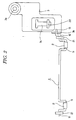
- Figure 2 is a plan view to a larger scale illustrating a main part of the disk holding device.
- One end of the wire 1 is coupled with a cam hole 4a provided in a large-diameter gear (rotary member) 4 of the loading block LB, through a linking plate (operating member) 3 and a coupling pin 3a provided on this linking plate 3.
- this cam hole 4a drive control of the rollers 2 is effected between a pressing position in which they press on the surface of the disk and a release position in which they are separated from the disk.
- the wire 1 functions as a resilient body that urges the rollers 2 by means of its spring properties, it does not need to have outstanding spring properties. In fact it is not necessarily essential for the wire 1 to have spring properties.
- the wire 1 comprises a central section which extends in straight-line fashion and bent sections respectively formed at both ends thereof. Furthermore, at one of the bent sections of the wire 1, there are successively formed, from the middle towards the tip, a roller shaft 11 and a swiveling shaft 12 and at the other bent section there is formed a coupling shaft 13, in addition to a roller shaft 11 and swiveling shaft 12.
- the shafts 11 to 13 are arranged in parallel with gaps therebetween.
- the roller shafts 11 rotatably support the rollers 2 as the rotary shafts of the rollers 2.
- the swiveling shafts 12 are rotatably supported on bearings 21 provided on the loading block LB and the coupling shaft 13 is rotatably supported on a bearing 3b provided in the linking plate 3.
- the linking plate 3 in addition to the bearing 3b that supports the coupling shaft 13 of the wire 1 and the coupling pin 3a that is inserted in the cam hole 4a, there is provided a linear guide hole 3c.
- the linking plate 3 is capable of sliding action in the direction of the guide hole 3c by insertion of the guide projection 22 provided on the loading block LB in this guide hole 3c.
- the large-diameter gear 4 is a member that rotates in order to perform the disk feeding action. During the operation of both of the loading action and the clamping action, it rotates continuously in the clockwise direction in the drawing; during the operation of both of the clamping release action and the unloading action, it rotates continuously in the anti-clockwise direction in the drawing.
- the cam hole 4a of the large diameter gear 4 during the loading action and unloading action, holds the rollers 2 in the pressing position and, matching the timing of the clamping action and the clamping release action, moves the rollers 2 between the pressing position and the released position.
- Figure 3 is a side view showing the operation of the wire 1 and the rollers 2, (A) illustrating the pressing condition and (B) illustrating the release condition, respectively.
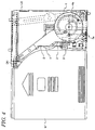
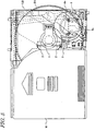
- Figure 4 to Figure 6 are plan views illustrating in step fashion the disk feeding action of a disk change device having a disk holding device, Figure 4 illustrating the initial condition, Figure 5 the loading action completed condition and Figure 6 the clamping action completed condition, respectively.
- M indicates the magazine.
- the linking plate 3 Whilst the large-diameter gear 4 is performing the loading action by rotating from this initial condition, the linking plate 3 is held at the end position (initial position) on the left-hand side in the drawing by the cam hole 4a, so the rollers 2 are held in the pressing position as shown in Figure 3(A). That is, the rollers 2 are held in a condition pressing against the surface of the disk D by the urging force of the wire 1. Consequently, since, during the loading action, the rollers 2 maintain the pressing condition whilst rotating on the surface of the moving disk D, the surface on the opposite side of the disk D can be pressed against the disk holder DH by these rollers 2.
- the rollers 2 are shifted to the release position so that the disk D is put in a condition in which it is capable of rotation.
- the surface of the disk D can be pressed against the disk holder by the rollers 2. Because of this, the rollers 2 move relatively to the disk D with their surface continuously pressed against the surface of the disk D, with no possibility of their rubbing against the surface of the disk D. There is therefore no possibility of damage to the surface of the disk D or of increase of the load on the drive system during the loading action, as there was with the prior art in which a fixed plate spring was employed.
- rollers 2 are made of rubber and can absorb impacts occurring on contact of the rollers and the disk surface, the loading action and unloading action can be made more stable.
- the constitution in the vicinity of the disk pressing section can be made extremely compact and simplified compared with the case where the rollers 2 and the wire 1 are provided separately. Furthermore, since the processes of severing and bending the wire are easy, this is advantageous from the point of view of productivity.
- the wire 1 can be directly rotated by means of the sliding action of the linking plate 3 and the position of the rollers 2 can thus be changed simply by rotating the wire 1 itself.
- the constitution of the drive control section from the cam hole 4a to the wire 1 can be made compact and simplified and there is no need for a special member for changing the position of the rollers 1, so the constitution of the vicinity of the disk pressing section can be made more compact and simplified. Also, as described above, processing of the wire can easily be performed, so providing the roller shafts 11, swiveling shaft 12 and coupling shaft 13 is easy.
- the disk pressing section can be subjected to drive control in accordance with the rotation of the large-diameter gear 4 of the loading block LB, the position of the disk pressing section can be suitably changed over matching the operating timing of the disk feed action and/or the clamping action.
- drive control of the disk pressing section can easily be realized with the desired timing by selection of the dimensions and shape of the cam hole 4a provided on the large-diameter gear 4.
- the constitution of the drive control section can be made extremely compact and simplified.
- the present invention can also be applied to cases in which the surface of the disk is pressed against the disk holder during clamping.
- a disk change device to which the present invention is applied comprises separate pressing means that presses the surface of the disk against the disk holder only during disk feeding but is constructed such that during the clamping action the disk is in an uncontrolled condition, it is necessary to press the disk against the disk holder in order to prevent displacement of the disk position in the uncontrolled condition.
- the disk holding device according to the present invention can be adapted to press the surface of the disk against the disk holder only during clamping. And since the disk pressing section does not slide over the surface of the disk during clamping, the rollers of Figure 2 can be dispensed with.
- Figure 7 is a cross-sectional view to a larger scale illustrating a main part of a disk holding device according to a second embodiment in which the rollers are dispensed with. As shown in this Figure 7, in this embodiment, both the disk pressing section and the resilient body that urges this are constituted solely by a single wire 30.
- a disk pressing section 31 and swiveling shaft 32 there are successively formed, from the center towards the tip, a disk pressing section 31 and swiveling shaft 32.
- a coupling shaft 33 At the other bent section, there are formed, in addition to the disk pressing section 31 and swiveling shaft 32, a coupling shaft 33. That is, apart from the fact that, by removing the rollers 2 from the roller shafts 11 of Figure 2 and using these as disk pressing sections 31, the surface of the disk D is directly pressed against by these disk pressing sections 31, the construction of the wire 30 is similar to that of the wire 1 shown in Figure 2.
- the construction of the other portions is similar to that in the case of the first embodiment shown in Figure 1, it is modified in that the cam hole 4a of the large-diameter gear 4 holds the disk pressing section 31 in the release position between the loading action and the unloading action and shifts the disk pressing section 31 from the release position to the pressing position in accordance with the timing of the clamping action and the clamping release action and, in addition, restores this to the release position.
- a magazine M may be employed having a construction capable of pressing the disk surface against the disk holder.
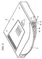
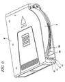
- Figure 8 and Figure 9 are perspective views respectively showing such a magazine M from different directions.
- This magazine M comprises a holder support projection 41 that supports the left and right edges of each individual disk holder DH and is so constructed that, in a condition in which a disk holder DH holding a disk D is accommodated within the magazine M, the surface of the disk D is pressed against the disk holder DH by the holder support projection 41.
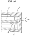
- Figure 10 is a cross-sectional view to a larger scale illustrating the principles of applying pressure to a disk by the holder support projection 41 of the magazine M shown in Figure 8 and Figure 9.
- a recess having a depth substantially the same as the thickness of the disk, by a support plate 42 and side walls 43 that project upwards from the left and right edges of a support plate 42, the disk D being accommodated in this recess.
- the upper surface of the disk D is in a position substantially coplanar with the upper surface of the disk holder DH and somewhat higher than the disk holder DH.
- the distance between the adjacent holder support projections 41 of the magazine M is set to the minimum necessary dimension that will permit sliding of a disk holder DH holding a disk D without obstruction. For this reason, it is arranged that, in a condition in which a disk holder DH is accommodated in the magazine M, the disk D should be pressed against the disk holder DH by the undersurface of a holder support projection 41.
- the disk pressing section 31 of the wire 30 is held in the release position so that the pressing of the disk D is performed by means of the holder support projection 41 of the magazine M. Then, at the point where the loading action has terminated, the disk holder DH is extracted from the magazine M and, at the time point where the left and right edges of the disk D held in the disk holder DH are separated from the undersurface of the holder support projection 41 and pressing against the disk by the holder support projection 41 of the magazine M or by the equivalent member on the mechanism side is released, the disk pressing section 31 of the wire 30 is shifted into the pressing position.
- the disk D that has been released from the holder support projection 41 of the magazine M or the equivalent member on the mechanism side is pressed against the disk holder DH by the disk pressing section 31 of the disk holding device according to the present invention so that positional displacement of the disk D can be prevented.
- the disk D is put in a condition in which it is capable of rotation by shifting the disk pressing section 31 to the release position during the process of clamping the disk D or after clamping has been completed.
- the disk change device when the disk change device is constituted such that it comprises separate disk pressing means during disk feed such as a holder support projection 41 of the magazine M or an equivalent member on the mechanism side and the disk is in an uncontrolled condition during clamping, with the disk holding device according to the present invention, displacement of the disk position can be prevented by pressing against the disk D during the clamping action.
- the disk pressing section 31 is accommodated in the release position, so, during the subsequent disk playback action, there is no possibility of the disk D being inappropriately pressed by the disk pressing section 31, so the disk playback action can be performed satisfactorily.
- the constitution in the vicinity of the disk pressing section can be made extremely compact and simplified compared with the case where rollers 2 are employed.
- the wire forming the wire 30 can easily be subjected to processing such as severing or bending and in this embodiment there is no need to mount rollers on the wire, so this is even more advantageous from the point of view of productivity and assembly of the device. It should be noted that it is not necessarily essential for the wire 30 that the constitutes the disk pressing section 31 to have spring properties.
- the same advantages are obtained as in the case of the first embodiment, in that the position of the disk pressing section can be suitably changed over matching the operating timing of the disk feed action or clamping action, in that drive control of the disk pressing section can easily be realized with the desired timing by selection of the shape and dimensions of the cam hole and in that the constitution of the drive control section can be made extremely compact and simplified due to the use of the existing large-diameter gear 4.
- the present invention is not restricted to the embodiments described above but could be implemented in various other modified modes within the scope of the present invention.
- the shape of the wire could be suitably altered or, as a modified example of the first embodiment, it would be possible to provide the wire and the rollers separately or to dispense with the rollers.
- rollers could be added.
- both the wire and rollers may be given resilience but it is also possible to give resilience only to one or other of the wire and rollers or, further, it is possible to employ wire not having resilience and rollers not having resilience.
- a spring could be provided that urges the rollers, separately from the wire that supports the rollers.
- any of the rotary members associated with the disk feed action or clamping action may be suitably employed, depending on the construction of the disk change device.
- the shape of the cam provided in the rotary member is not restricted to being a cam hole and it would also be possible to provide a cam hole on the side of an operating member coupled with the disk pressing section as a coupling pin.
- the present invention relates to the disk holding device, there are no restrictions at all on the construction of the disk change device itself where this disk holding device is provided or on the magazine that is used therein; so long as it is necessary to press the surface of the disk against the disk holder during disk feeding or clamping, this can be applied in the same way to a disk change device having many different types of construction and the same excellent benefits obtained.
- the operating timing of the drive control of the disk pressing section can be freely set in accordance with requirements; for example, consideration may be given to a construction in which the disk surface is pressed against the disk holder during both disk feeding and clamping.
- a disk holding device that is capable of pressing the surface of a disk against a disk holder and which is of high operating reliability and which is compact and simplified and capable of wide application to disks having non-standard dimensions, without causing damage of the disk surface during disk feeding or clamping and without increasing the load on the drive system.
Landscapes
- Feeding And Guiding Record Carriers (AREA)
- Automatic Disk Changers (AREA)
Abstract
Description
Claims (7)
- A disk holding device for a disk change device capable of accommodating a plurality of disk holders that carry disks, that presses the surface of a disk against a disk holder during disk feeding and/or clamping, comprising:a disk pressing section arranged so as to be capable of operation between a pressing position where the disk pressing section is pressed against the surface of the disk and a release position where it is released from the disk; anda drive control section that performs drive control of said disk pressing section between the pressing position and the release position.
- The disk holding device according to claim 1, wherein the disk pressing section is a rotatable roller.
- The disk holding device according to claim 2, wherein said roller is formed of resilient material.
- The disk holding device according to any of claims 1 to 3, wherein said disk pressing section is urged by a resilient body.
- The disk'holding device according to claim 4, wherein said resilient body is formed by a wire having spring properties.
- The disk holding device according to any of claims 1 to 5, wherein said drive control section comprises a cam provided in a rotary member for disk feeding and/or clamping and an operating member that is driven by this cam and performs drive control of the disk pressing section between said pressing position and release position.
- The disk holding device according to any of claims 1 to 6, wherein said drive control section is adapted to control said disk pressing section to the pressing position at least during disk clamping.
Applications Claiming Priority (3)
| Application Number | Priority Date | Filing Date | Title |
|---|---|---|---|
| JP2000148553 | 2000-05-19 | ||
| JP2000148553 | 2000-05-19 | ||
| PCT/JP2001/004149 WO2001088914A1 (en) | 2000-05-19 | 2001-05-18 | Disk holding device |
Publications (3)
| Publication Number | Publication Date |
|---|---|
| EP1306838A1 true EP1306838A1 (en) | 2003-05-02 |
| EP1306838A4 EP1306838A4 (en) | 2005-07-27 |
| EP1306838B1 EP1306838B1 (en) | 2007-08-15 |
Family
ID=18654563
Family Applications (1)
| Application Number | Title | Priority Date | Filing Date |
|---|---|---|---|
| EP01932132A Expired - Lifetime EP1306838B1 (en) | 2000-05-19 | 2001-05-18 | Disk holding device |
Country Status (5)
| Country | Link |
|---|---|
| US (1) | US6961948B2 (en) |
| EP (1) | EP1306838B1 (en) |
| JP (1) | JP4627954B2 (en) |
| DE (1) | DE60129984T2 (en) |
| WO (1) | WO2001088914A1 (en) |
Families Citing this family (6)
| Publication number | Priority date | Publication date | Assignee | Title |
|---|---|---|---|---|
| US6951028B2 (en) * | 2003-05-21 | 2005-09-27 | Hanpin Electron Co., Ltd. | CD inserting mechanism of a CD player without loading plate |
| TWI254915B (en) * | 2004-08-06 | 2006-05-11 | Lite On It Corp | Disc changer |
| CA2842402C (en) | 2005-03-10 | 2016-02-23 | Gen-Probe Incorporated | Systems and methods to perform assays for detecting or quantifying analytes within samples |
| CN102122516A (en) * | 2010-01-12 | 2011-07-13 | 建兴电子科技股份有限公司 | Advance and eject mechanism for slot-load optical drives |
| US9046507B2 (en) | 2010-07-29 | 2015-06-02 | Gen-Probe Incorporated | Method, system and apparatus for incorporating capacitive proximity sensing in an automated fluid transfer procedure |
| AU2012222178B2 (en) | 2011-02-24 | 2014-12-18 | Gen-Probe Incorporated | Systems and methods for distinguishing optical signals of different modulation frequencies in an optical signal detector |
Family Cites Families (19)
| Publication number | Priority date | Publication date | Assignee | Title |
|---|---|---|---|---|
| US4635150A (en) * | 1982-02-22 | 1987-01-06 | Victor Company Of Japan Ltd. | Apparatus for automatically selecting and reproducing a recording medium |
| JPS6282554A (en) * | 1985-10-07 | 1987-04-16 | Pioneer Electronic Corp | Multi-disk player |
| JPH0640417B2 (en) * | 1985-10-07 | 1994-05-25 | パイオニア株式会社 | Multi-disc player |
| JP3393345B2 (en) * | 1992-10-31 | 2003-04-07 | ソニー株式会社 | Disk playback device, memory control circuit, and memory control method |
| JP2590361Y2 (en) * | 1993-03-10 | 1999-02-10 | アルパイン株式会社 | Disk unit |
| US5631882A (en) * | 1994-06-17 | 1997-05-20 | Nakamichi Corporation | Disk changer device for use with a personal computer and control method for same |
| JP3541484B2 (en) * | 1995-02-13 | 2004-07-14 | ソニー株式会社 | Playback device, recording device |
| JP3001810B2 (en) * | 1996-06-13 | 2000-01-24 | 富士通テン株式会社 | Record carrier reproduction / recording device |
| JP3534542B2 (en) * | 1996-07-04 | 2004-06-07 | パイオニア株式会社 | Disc playback device |
| JP3363712B2 (en) * | 1996-08-06 | 2003-01-08 | 株式会社リコー | Optical disk drive |
| KR100243244B1 (en) * | 1996-10-31 | 2000-02-01 | 윤종용 | Apparatus and method of optical disc player |
| DE69819847T2 (en) * | 1997-03-10 | 2004-09-02 | Mitsubishi Denki K.K. | PLATE SYSTEM |
| KR100288402B1 (en) * | 1997-12-29 | 2001-05-02 | 윤종용 | Method for confronting buffer underrun of optical disc drive |
| JP3565248B2 (en) * | 1998-04-17 | 2004-09-15 | パイオニア株式会社 | Disc playback device |
| JP2000293920A (en) * | 1999-04-01 | 2000-10-20 | Aiwa Co Ltd | Auto-changer device for information equipment |
| US6751181B1 (en) * | 1999-09-28 | 2004-06-15 | Sony Corporation | Recording and/or reproducing device for disks |
| US6693857B1 (en) * | 1999-11-04 | 2004-02-17 | Thomson Licensing S.A. | Data buffer management to enable apparent simultaneous record and playback from a rewritable digital disk |
| JP3594547B2 (en) * | 1999-11-22 | 2004-12-02 | 三洋電機株式会社 | Data recording device |
| US6704387B1 (en) * | 2001-09-11 | 2004-03-09 | Oak Technology, Inc. | Method and apparatus for normalized bit counting |
-
2001
- 2001-05-18 DE DE60129984T patent/DE60129984T2/en not_active Expired - Lifetime
- 2001-05-18 JP JP2001584425A patent/JP4627954B2/en not_active Expired - Fee Related
- 2001-05-18 WO PCT/JP2001/004149 patent/WO2001088914A1/en not_active Ceased
- 2001-05-18 US US10/276,600 patent/US6961948B2/en not_active Expired - Fee Related
- 2001-05-18 EP EP01932132A patent/EP1306838B1/en not_active Expired - Lifetime
Also Published As
| Publication number | Publication date |
|---|---|
| JP4627954B2 (en) | 2011-02-09 |
| EP1306838A4 (en) | 2005-07-27 |
| EP1306838B1 (en) | 2007-08-15 |
| US20030156507A1 (en) | 2003-08-21 |
| JPWO2001088914A1 (en) | 2004-01-08 |
| DE60129984T2 (en) | 2008-05-08 |
| WO2001088914A1 (en) | 2001-11-22 |
| DE60129984D1 (en) | 2007-09-27 |
| US6961948B2 (en) | 2005-11-01 |
Similar Documents
| Publication | Publication Date | Title |
|---|---|---|
| US4627042A (en) | Loading apparatus for a disc | |
| US6250552B1 (en) | Card reader having means for reducing the size of the card reader | |
| US20030227856A1 (en) | Disk loading device for disk player and a method for using the same | |
| CN100437795C (en) | Disk drive device | |
| EP0944073A1 (en) | Disk ejection device | |
| US6961948B2 (en) | Disk holding device | |
| US20010021157A1 (en) | Disk device having disk transferring mechanism capable of being made thin | |
| EP0833320B1 (en) | Disk carrier mechanism | |
| EP1052636B1 (en) | Disk clamp mechanism of disk device | |
| US7987474B2 (en) | Disc ejecting device for slot-in type disc drive | |
| EP0548465B1 (en) | Laser disk player | |
| US20010021156A1 (en) | Disk device having disk transferring mechanism capable of shortening disk replacement time--in its place | |
| JP2915609B2 (en) | Card placement device | |
| KR19990045653A (en) | Disk device | |
| KR100300620B1 (en) | Storage medium transporting mechanism | |
| EP1087389A1 (en) | Disc unit | |
| EP1087391B1 (en) | Disc unit | |
| US20090044210A1 (en) | Slot-in Type Disk Apparatus | |
| JP3638041B2 (en) | Disk centering mechanism | |
| KR20050084026A (en) | Disk player | |
| EP0434136A1 (en) | Disc-record player and centring device for use in the player | |
| KR100854136B1 (en) | disk driving system of slot-in type | |
| KR100461297B1 (en) | Optical disk roading apparatus for optical disk drive | |
| US5021900A (en) | Tape guide driving device for rotating head type tape player | |
| JP2587459Y2 (en) | Disc-shaped recording medium insertion / ejection device |
Legal Events
| Date | Code | Title | Description |
|---|---|---|---|
| PUAI | Public reference made under article 153(3) epc to a published international application that has entered the european phase |
Free format text: ORIGINAL CODE: 0009012 |
|
| 17P | Request for examination filed |
Effective date: 20021219 |
|
| AK | Designated contracting states |
Designated state(s): AT BE CH CY DE DK ES FI FR GB GR IE IT LI LU MC NL PT SE TR |
|
| AX | Request for extension of the european patent |
Extension state: AL LT LV MK RO SI |
|
| RBV | Designated contracting states (corrected) |
Designated state(s): DE FR GB |
|
| A4 | Supplementary search report drawn up and despatched |
Effective date: 20050609 |
|
| RIC1 | Information provided on ipc code assigned before grant |
Ipc: 7G 11B 17/26 A Ipc: 7G 11B 17/22 B |
|
| GRAP | Despatch of communication of intention to grant a patent |
Free format text: ORIGINAL CODE: EPIDOSNIGR1 |
|
| GRAS | Grant fee paid |
Free format text: ORIGINAL CODE: EPIDOSNIGR3 |
|
| GRAA | (expected) grant |
Free format text: ORIGINAL CODE: 0009210 |
|
| AK | Designated contracting states |
Kind code of ref document: B1 Designated state(s): DE FR GB |
|
| REG | Reference to a national code |
Ref country code: GB Ref legal event code: FG4D |
|
| REF | Corresponds to: |
Ref document number: 60129984 Country of ref document: DE Date of ref document: 20070927 Kind code of ref document: P |
|
| ET | Fr: translation filed | ||
| PLBE | No opposition filed within time limit |
Free format text: ORIGINAL CODE: 0009261 |
|
| STAA | Information on the status of an ep patent application or granted ep patent |
Free format text: STATUS: NO OPPOSITION FILED WITHIN TIME LIMIT |
|
| 26N | No opposition filed |
Effective date: 20080516 |
|
| REG | Reference to a national code |
Ref country code: FR Ref legal event code: PLFP Year of fee payment: 16 |
|
| PGFP | Annual fee paid to national office [announced via postgrant information from national office to epo] |
Ref country code: GB Payment date: 20160518 Year of fee payment: 16 Ref country code: DE Payment date: 20160510 Year of fee payment: 16 |
|
| PGFP | Annual fee paid to national office [announced via postgrant information from national office to epo] |
Ref country code: FR Payment date: 20160412 Year of fee payment: 16 |
|
| REG | Reference to a national code |
Ref country code: DE Ref legal event code: R119 Ref document number: 60129984 Country of ref document: DE |
|
| GBPC | Gb: european patent ceased through non-payment of renewal fee |
Effective date: 20170518 |
|
| REG | Reference to a national code |
Ref country code: FR Ref legal event code: ST Effective date: 20180131 |
|
| PG25 | Lapsed in a contracting state [announced via postgrant information from national office to epo] |
Ref country code: DE Free format text: LAPSE BECAUSE OF NON-PAYMENT OF DUE FEES Effective date: 20171201 Ref country code: GB Free format text: LAPSE BECAUSE OF NON-PAYMENT OF DUE FEES Effective date: 20170518 |
|
| PG25 | Lapsed in a contracting state [announced via postgrant information from national office to epo] |
Ref country code: FR Free format text: LAPSE BECAUSE OF NON-PAYMENT OF DUE FEES Effective date: 20170531 |