EP1306806A2 - Signaling adaptive-quantization matrices in JPEG using end-of-block codes - Google Patents
Signaling adaptive-quantization matrices in JPEG using end-of-block codes Download PDFInfo
- Publication number
- EP1306806A2 EP1306806A2 EP02020241A EP02020241A EP1306806A2 EP 1306806 A2 EP1306806 A2 EP 1306806A2 EP 02020241 A EP02020241 A EP 02020241A EP 02020241 A EP02020241 A EP 02020241A EP 1306806 A2 EP1306806 A2 EP 1306806A2
- Authority
- EP
- European Patent Office
- Prior art keywords
- data block
- jpeg
- image
- quantize
- data
- Prior art date
- Legal status (The legal status is an assumption and is not a legal conclusion. Google has not performed a legal analysis and makes no representation as to the accuracy of the status listed.)
- Withdrawn
Links
Images


Classifications
-
- H—ELECTRICITY
- H04—ELECTRIC COMMUNICATION TECHNIQUE
- H04N—PICTORIAL COMMUNICATION, e.g. TELEVISION
- H04N19/00—Methods or arrangements for coding, decoding, compressing or decompressing digital video signals
- H04N19/10—Methods or arrangements for coding, decoding, compressing or decompressing digital video signals using adaptive coding
- H04N19/102—Methods or arrangements for coding, decoding, compressing or decompressing digital video signals using adaptive coding characterised by the element, parameter or selection affected or controlled by the adaptive coding
- H04N19/124—Quantisation
-
- H—ELECTRICITY
- H04—ELECTRIC COMMUNICATION TECHNIQUE
- H04N—PICTORIAL COMMUNICATION, e.g. TELEVISION
- H04N19/00—Methods or arrangements for coding, decoding, compressing or decompressing digital video signals
- H04N19/46—Embedding additional information in the video signal during the compression process
-
- H—ELECTRICITY
- H04—ELECTRIC COMMUNICATION TECHNIQUE
- H04N—PICTORIAL COMMUNICATION, e.g. TELEVISION
- H04N19/00—Methods or arrangements for coding, decoding, compressing or decompressing digital video signals
- H04N19/60—Methods or arrangements for coding, decoding, compressing or decompressing digital video signals using transform coding
Definitions
- the present invention relates in general to the field of adaptive quantization of digitized images, and in particular, to JPEG adaptive-quantization signaling.
- JPEG Joint Photographic Experts Group image-compression standard
- JPEG is the most widely-used method for still image compression.
- the most-commonly-used JPEG mode is referred to as the "baseline sequential mode.”
- a less-commonly used mode of JPEG is the "progressive mode.”
- a baseline-sequential JPEG file is stored as a single scan of an image.
- JPEG progressive mode divides the image into a series of scans. A first scan shows the image at an equivalent of a very low quality setting. Following scans gradually improve quality of the displayed image. Each scan adds to the data already provided so that the total storage requirement is roughly the same as for a baseline JPEG image of the same quality as the final scan.
- An advantage of progressive JPEG is that if an image is being viewed on-the-fly as it is transmitted, one can see an approximation of the whole image very quickly, with gradual improvement of quality as one waits longer.
- a disadvantage is that each scan takes about the same amount of computation to display as a whole baseline JPEG file would.
- Adaptive quantization refers to adaptively varying a quantization matrix (Q matrix) from data block to data block using an encoder.
- adaptive quantization helps to solve some of the problems discussed above, adaptive quantization cannot be used unless a mechanism for signaling the adaptation to the decoder is devised.
- the decoder must vary the Q matrix at each data block in exactly the same manner as the encoder in order to obtain the benefits of adaptive quantization.
- U.S. Patent No. 5,157,488 to Pennebaker (Pennebaker) describes the use of an extra "color" component for signaling. Because JPEG can accommodate any number of components (red, green, blue, and possibly others), extra components can be sub-sampled by an integer factor relative to original components.
- a decoder that can interpret Pennebaker's signaling scheme can be programmed to recognize how the extra component signals a varying Q matrix.
- the decoding system can have a standard encoder rather than one that is "aware" of Pennebaker's signaling scheme. In such a case, the extra component would be decoded incorrectly, limiting the applicability of Pennebaker's approach.
- U.S. Patent No. 5,822,458 to Silverstein, et. al discloses use of the parity of a sum of quantized DCT coefficients in each data block for signaling purposes. After the DCT coefficients are divided by the corresponding elements of the Q matrix, they are rounded to an integer value. Values having fractional portions near to 0.5 can be rounded either up or down without incurring significant additional error. For example, 11.499 can be rounded to either 11 or 12, the error being approximately the same in either case. Silverstein discloses taking the coefficient closest to the quantization midpoint and rounding the midpoint up or down so that the parity of the data block is even or odd. The parity therefore signals information that could be used for adaptive quantization.
- Silverstein's signaling scheme requires a search of the 64 coefficients of each data block in order to determine the coefficient that is closest to the midpoint, which can result in slower encoding and increased computational load.
- rounding by amounts up to 1 might be required. In such cases, the rounding errors could result in less-than-desirable results.
- the present invention provides for signaling JPEG adaptive-quantization matrices using end-of-block (EOB) codes.
- EOB codes normally reserved for use in the less common progressive mode can be sued in the more-common baseline-sequential mode to identify respective quantization matrices.
- a method of JPEG adaptive quantization for image compression includes associating each of a plurality of quantization matrices (Q matrices) to a corresponding end-of-block (EOB) code of a plurality of EOB codes and performing a discrete cosine transform (DCT) of a digitized image file that includes a plurality of data blocks.
- DCT discrete cosine transform
- the discrete-cosine-transformed digitized image file is quantized using at least two of the plurality of Q matrices.
- the EOB code that corresponds to the Q matrix used to quantize the discrete cosine transform of the at least one data block is included in the quantized discrete-cosine-transformed digitized image file for at least one of the data blocks.
- a JPEG image-compression system includes a discrete-cosine-transform element.
- the discrete-cosine-transform element is adapted to perform a discrete-cosine transform of each data block of image data.
- the system also includes a quantizer adapted to quantize each discrete-cosine-transformed data block of the image data using a matrix selected from a plurality of Q matrices.
- the quantizer is also adapted to identify, for each discrete-cosine-transformed data block of the image data, which of the plurality of matrices was used to quantize the discrete-cosine-transformed data block of the image data.
- a JPEG image file includes a Huffman-code table.
- the Huffman code table includes a plurality of EOB codes. Each of the EOB codes corresponds to a particular Q matrix.
- the image file also includes a plurality of data blocks. One of the plurality of EOB codes is included relative to each of the data blocks. The code included corresponds to the particular Q matrix used to quantize a discrete cosine transform of that data block.
- a JPEG image compression-decompression system includes an encoder for encoding an image file.
- the encoder includes a quantizer.
- the quantizer is adapted to quantize the image file using a plurality of Q matrices.
- the image file includes a plurality of data blocks.
- An EOB code identifying which of the plurality of Q matrices was used to quantize a discrete cosine transform of that data block is associated with each data block.
- the image compression-decompression system also includes a decoder for decoding the image file.
- the decoder includes a dequantizer adapted to dequantize the image file using the plurality of Q matrices.
- the dequantizer reads, for each data block, the EOB code associated with that data block in order to determine which of the plurality of Q matrices was used to quantize the discrete cosine transform of that data block.
- An article of manufacture for JPEG-image-compression adaptive quantization includes at least one computer-readable medium and processor instructions contained on the at least one computer-readable medium.
- the processor instructions are configured to be readable from the at least one computer-readable medium.
- the at least one processor reads the processor instructions.
- the instructions cause the at least one processor to operate to associate each of a plurality of Q matrices to a corresponding EOB code of a plurality of EOB codes.
- the processor instructions also cause the processor to operate to quantize a discrete cosine transform of each of a plurality of data blocks of an image file using at least two of the plurality of Q matrices.
- the processor instructions also cause the processor to operate to include in the image file, for at least one data block of the plurality of data blocks, the EOB code corresponding to the Q matrix used to quantize the discrete cosine transform of the at least one data block of the plurality of data blocks.
- a decoder for decoding a JPEG image file includes a dequantizer adapted to dequantize the JPEG image file using a plurality of quantization matrices.
- the dequantizer reads, for each data block of a plurality of data blocks, an end-of-block code associated with that data block in order to determine which of a plurality of quantization matrices was used to quantize a discrete cosine transform of that data block.
- the present invention provides the image-quality benefits of adaptive quantization in a JPEG context without the disadvantages of prior art adaptive-quantization systems. Specifically, the invention provides for compatibility with JPEG decoders that are not aware of the adaptive-decoding scheme, although the results are of lower quality than those achievable by a decoder in accordance with the invention.
- the signaling scheme is less computationally intensive than prior art schemes and requires no additional bandwidth. In contrast to Silverstein's signaling scheme, the present signaling scheme does not compromise image quality.
- FIG. 1 is a block diagram of an image-compression system 100.
- the system 100 can be used to compress a digitized image according to the JPEG baseline sequential mode and includes a discrete-cosine-transform-based (DCT-based) encoder 102, a quantizer-specifications table 108, and an entropy-encoder specifications table 110.
- the DCT-based encoder 102 includes a DCT element 112, a quantizer 114, and an entropy encoder 116.
- the entropy encoder 116 comprises a Huffman encoder.
- the quantizer specifications table 108, entropy encoder specifications table 110, DCT element 112, quantizer 114, and entropy encoder 116 can be implemented as one or more software modules, as firmware, as hardware units, or any combination thereof.
- a blocked source image 104 is input into the system 100.
- a source image may be one of the following: a grayscale image; a color image having three color components (e.g., red, green, blue); or a multi-component image having up to 255 components (i.e., a multi-band image).
- the source image if a color image, is usually transformed into a luminance-chrominance component image (Y-Cb-Cr) and the chrominance components are sub-sampled by a factor of 2 to take advantage of the relative insensitivity of the human visual system to detail in the chrominance space. Following color-space transformation and sub-sampling, the source image typically comprises N parts.
- each of the N parts of the source image is divided into nonoverlapping data blocks, usually of 8x8 pixels.
- the blocked source image 104 which represents a source image after the source image has been divided into data blocks, next undergoes a DCT, which is performed by the DCT element 112.
- the DCT performed by the DCT element 112 maps data of the image 104 from the spatial domain to the frequency domain.
- the DCT is calculated by the DCT element 112 for each data block of the image 104, resulting in a plurality of DCT coefficients for each data block.
- the coefficient D(1,1) is referred to as the DC coefficient and the remaining coefficients are referred to as the AC coefficients.
- the DC coefficient has zero frequency in both the i and the j dimensions, while the AC coefficients have increasing frequency as i and j increase.
- the quantizer 114 quantizes the DCT coefficients of the image 104 by dividing each coefficient D(i,j) by the corresponding Q matrix entry of that coefficient and rounding to the nearest integer.
- the Q matrix can be obtained by the quantizer 114 from the quantizer-specifications table 108.
- the quantizer 114 quantizes the DCT coefficients of the image 104 by applying the equation: wherein Q(i,j) can be found in the quantizer-specifications table 108 and round represents rounding to the nearest integer.
- the entropy encoder 116 encodes the quantized coefficients Dq (i,j) of the image 104 from the quantizer 114 in order to minimize redundancy.
- the quantized DC coefficients are coded separately from the quantized AC coefficients because there is usually strong correlation between DC coefficients of adjacent data blocks.
- zigzag scanning and run-length encoding of the quantized coefficients must be performed by the encoder 116.
- Table 2 illustrates an exemplary matrix D q .
- Table 3 illustrates the order of zigzag scanning of an exemplary matrix D q .
- the entropy encoder 116 scans the matrix D q of Table 2 in a zigzag manner, starting with D q (1,1), which serves to order the quantized coefficients by frequency.
- the zigzag scanning orders the quantized coefficients from least to greatest frequency.
- Table 3 illustrates the order in which the coefficients of D q shown in Table 2 are zigzag scanned.
- the coefficient of D q with value 2 as shown in Table 1 occupies the fifth position
- the coefficient with value 10 occupies the zeroth position
- the coefficient with value 16 occupies the 23rd position.
- the AC coefficients are run-length encoded. As mentioned above, the DC coefficients are encoded separately from the AC coefficients. If D q is the 8x8 matrix shown in Table 2, the DC coefficient is 10 (i.e., D q (1,1)). Run-length coding of the AC coefficients shown in Table 2 produces a sequence of pairs (R,V), wherein R represents the preceding number of zeros of the scan and V represents the value of the non-zero coefficient that follows the number of zeros.
- the first symbol, ZRL is used to designate a gap of 15 or more zeros after which the last non-zero coefficient of the sequence has not yet been reached.
- a second special symbol which indicates the end of the data block, end-of-block (EOB) is generated.
- the run-length-code sequence is: (0,1), (0,-1), (2,2), ZRL, (2,16), EOB. Because the coefficient with value 2 of D q as shown in Table 2 is in the fifth position of the scan and the coefficient with value 16 is in the 23rd position of the scan, there are 17 zeros between the two coefficients.
- the ZRL symbol of the run-length code sequence accounts for 15 of those zeros.
- the next entry in that sequence is (2, 16), which accounts for the remaining two zeros and the value 16.
- the EOB symbol indicates that the coefficient with value 16 is the last non-zero value of D q .
- the entropy encoder 116 encodes each symbol of the run-length-code sequence using a predefined Huffman-code table, which table can be found by the entropy encoder 116 from the encoder-specifications table 110.
- a predefined Huffman-code table which table can be found by the entropy encoder 116 from the encoder-specifications table 110.
- the output of the encoder 116 is a compressed image data 106.
- the compressed image data 106 can be decompressed using a JPEG-compliant decompression system that essentially performs the inverse of the functions described in connection with FIG.1.
- An exemplary decompression system is shown in FIG. 2, which is discussed in more detail below.
- Each entry in Table 4 has a corresponding Huffman code.
- the Huffman codes are not shown herein, but can be found in W. B. Pennebaker and J. L. Mitchell, JPEG: Still image data compression standard , New York: Van Nostrand Reinhold, 1993, which is incorporated by reference.
- the Huffman code for EOB might be 1010
- the Huffman code for ZRL might be 1111111110111.
- the Huffman codes can be optimized for each image using a JPEG-specified algorithm.
- a complete Huffman-code table is included with each image in a JPEG file header.
- the JPEG progressive mode is typically used in applications in which a low-resolution image is sent first and is followed by progressively higher-resolution images.
- the baseline sequential mode is by far the most-often-used JPEG mode.
- a computer operating in accordance with instructions from a software store on a computer readable medium 118 aids the operation of the encoder 102 and the JPEG-image-compression adaptive-quantization process.
- FIG. 2 is a block diagram of an image-decompression system 200.
- the system 200 can be used to decompress an image compressed by, for example, the system 100, according to the JPEG baseline sequential mode.
- the system 200 can be connected to the system 100 by, for example, a wireless or wired communications link (not shown), including, but not limited to, the Internet or an intranet.
- the system 200 includes a DCT-based decoder 202, a dequantizer-specifications table 204, and an entropy-encoder specifications table 206.
- the DCT-based decoder 202 includes an inverse discrete-cosine-transform (IDCT) element 208, a dequantizer 210, and an entropy decoder 212.
- IDCT inverse discrete-cosine-transform
- the entropy decoder 212 comprises a Huffman decoder.
- the system 200 first decodes the compressed image data 106 by essentially performing the inverse of the entropy encoding performed by the entropy encoder 116; namely, Huffman decoding and run-length decoding.
- the entropy decoder 212 obtains the necessary Huffman code table specifications and run-length coding specifications from the entropy decoder specifications table 206.
- the compressed image data 106 is dequantized by the dequantizer 210, which essentially performs the inverse function of the quantizer 114.
- the dequantizer 210 obtains the Q matrix to be used during dequantization from the dequantizer specifications table 204.
- an IDCT is performed by the IDCT element 208 on the compressed image data 106, which results in a reconstructed image 214.
- JPEG permits only one Q matrix to be used for each color component.
- Dequantizer specifications table 204, entropy decoder specifications table 206, IDCT element 208, dequantizer specifications table 204, entropy decoder specifications table 206, IDCT element 208 dequantizer 210, and entropy decoder 212 can be implemented as one or more software modules, as firmware, as hardware units, or any combination thereof.
- Adaptive quantization refers to adaptively varying by an encoder of a quantization (Q) matrix from data block to data block by, for example, quantizing more coarsely in regions where the result will not be noticeable and quantizing less coarsely in areas where the result will be.
- Q quantization
- the JPEG standard uses one Q matrix for the DCT coefficients representing each color component, which Q matrix does not vary from data block to data block within a component. It would be desirable to be able to vary the Q matrix and to signal the variation to a decoder using standard JPEG syntax.
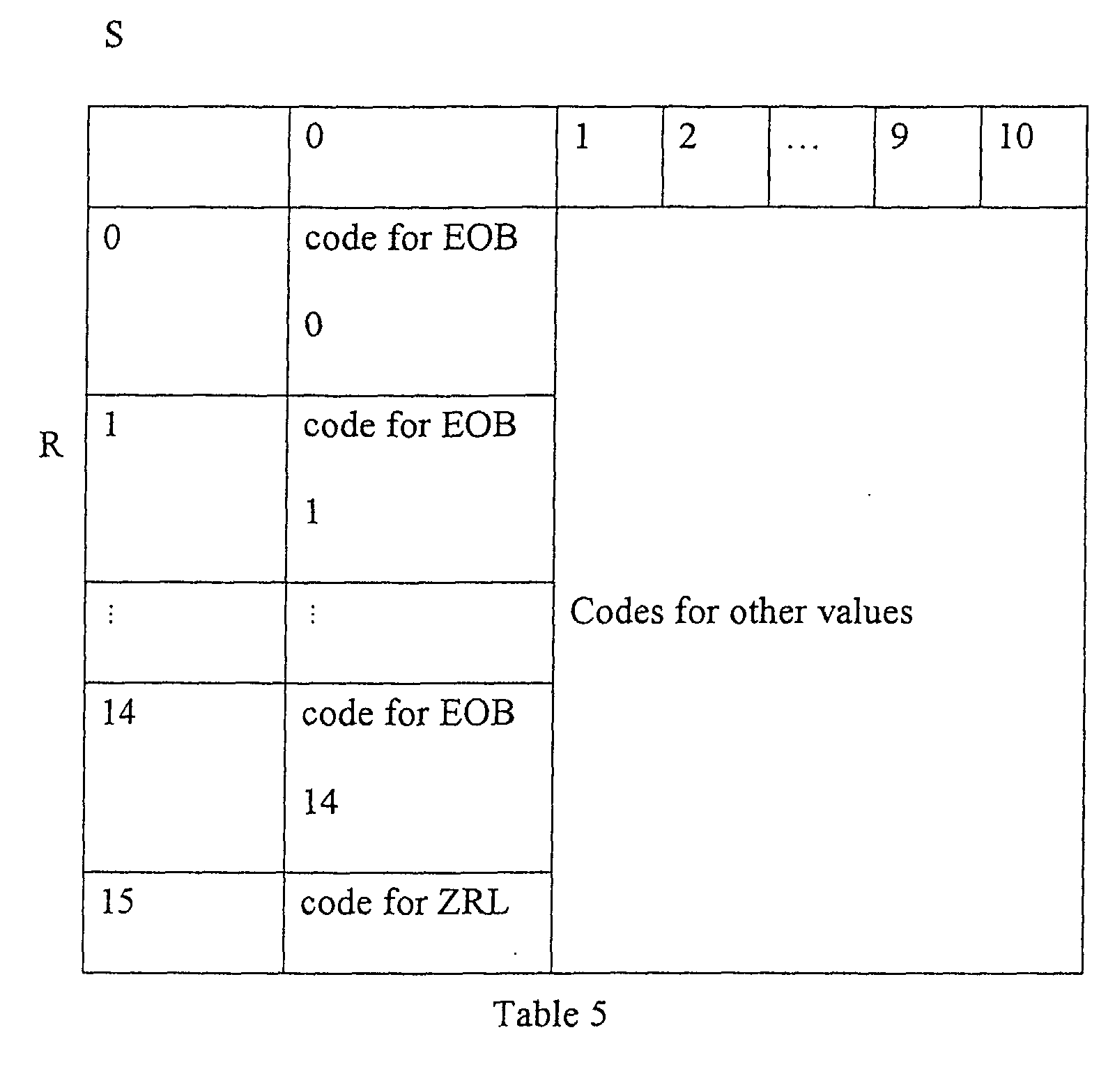
- Corresponding code words are defined in a Huffman code table (e.g., the Table 4).
- a standard JPEG decoder treats all of these codes as simply indicating an EOB.
- a Huffman code table according to an embodiment of the present invention is shown in Table 5.
- An advantage of having a total of 2-15 different codes for EOB is that an encoder can signal to a modified decoder to use of any one of 2-15 different specified Q matrices at each data block by choosing an EOB code for each Q matrix.
- a standard decoder treats all of these codes the same (i.e., merely as an EOB) and will therefore not vary the Q matrix.
- Embodiments of the present invention are not difficult to implement in either an encoder or a modified decoder, since unused slots in an already-existing table are filled in.
- the Huffman-code table is sent along with the image file to the decoder, as required by JPEG.
- a modified decoder reads the EOB code and uses the appropriate Q matrix to perform the inverse quantization.
- JPEG compression can result in at least two types of blocking artifacts: 1) visible boundaries between data blocks; and 2) ringing appears in the neighborhood of data-block edges.
- a given Q matrix produces both types of artifacts
- one way to reduce blocking artifacts is to use adaptive quantization.
- For smooth data blocks a smaller Q matrix, such as, for example, 0.75 Q, can be used, meaning that quantization error is reduced, and for data blocks containing edges, a larger Q matrix, such as, for example, 1.25 Q, can be used. More bits are allocated to smooth data blocks to avoid blocking artifacts, and the fewer bits are allocated to the edge data blocks.
- an adaptively-compressed image will require approximately the same file size as with standard compression.
- the adaptation of the Q matrix can be signaled by using two EOB codes, one for the smooth data blocks, and the other for the edge data blocks.
- the determination of whether the data block is a smooth or an edge data block is based on whether the last non-zero coefficient occurs early or late in a zigzag scan relative to a pre-determined threshold.
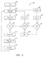
- FIG. 3 is a flow chart illustrating an embodiment of the present invention for decoding of an image encoded using varying Q matrices and placing entries of a data block thereof into a kth position in a buffer of decoded coefficients by both a standard decoder and by a decoder according to an embodiment of the present invention.
- a flow 300 can be implemented as one or more software modules, as firmware, as hardware units, or any combination thereof. In a preferred embodiment, the flow 300 is implemented by the system 200.
- a codeword that corresponds to the kth position is read from a Huffman code table.
- R and S are extracted from the codeword.
- step 314 a V value is determined from the value of S.
- step 316 V is placed in the kth position.
- a JPEG decoder adapted to operate according to the present invention proceeds to step 322 rather than to step 320.
- Operations of the modified decoder that vary from operation of the standard decoder are denoted by dashed lines.
- the R value of the codeword is read.
- a Q matrix corresponding to the R value that is used to decode the data block is obtained.
- the decoder accesses an index of Q matrices as a function of R in order to obtain the proper Q matrix. From step 326, execution moves to step 304, at which step the next codeword is read.
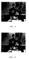
- FIGS. 4, 5, 6, and 7 are color images in accordance with embodiments of the present invention.
- FIG. 4 is an color image prior to compression.
- FIG. 5 is a color image that results from standard JPEG compression with a compression ratio of 25:1 of the image.
- FIG. 6 is a color image that results from the image of FIG. 4 being compressed using adaptive quantization, being signaled using EOB codes, and being decompressed using a modified decoder in accordance with an embodiment of the present invention.
- FIG. 7 is a color image that results from the image being compressed using the same adaptive quantization and signaling as FIG. 6, but being decompressed by a standard decoder.
- An adaptively-quantized image can be read by a standard decoder, although the result will not be as true to the original, uncompressed image, as if a standard, non-adaptively-quantized, JPEG image had been sent to the same decoder, because the standard decoder cannot vary the Q matrix used to decode the image to correspond to the Q matrix used to encode the image. Therefore, the adaptively-quantized image that has been decoded by a standard decoder (e.g., FIG. 7) is less sharp in edge regions that if it were decoded by a modified decoder (e.g., FIG. 6), although the adaptively-quantized image is quite clear in smooth regions.
- FIG. 6 The best result in terms of reduced blocking artifacts is obtained when an adaptively-quantized image is decoded by a modified decoder, as shown by FIG. 6.
- the fidelity of the image of FIG. 6 is better than that of the image of FIG. 5 relative to the image of FIG. 4 in terms of reduced blocking artifacts in edge regions.
- the images of both FIG. 5 and FIG. 6 possess greater fidelity relative to the uncompressed image of FIG. 4 than does the image of FIG. 7.
Landscapes
- Engineering & Computer Science (AREA)
- Multimedia (AREA)
- Signal Processing (AREA)
- Compression Or Coding Systems Of Tv Signals (AREA)
- Compression Of Band Width Or Redundancy In Fax (AREA)
- Compression, Expansion, Code Conversion, And Decoders (AREA)
Abstract
Description


| 10 | 1 | 2 | 0 | 0 | 0 | 0 | 0 |
| 1 | 0 | 0 | 0 | 0 | 0 | 0 | 0 |
| 0 | 0 | 0 | 0 | 0 | 0 | 0 | 0 |
| 0 | 0 | 0 | 0 | 0 | 0 | 0 | 0 |
| 0 | 0 | 16 | 0 | 0 | 0 | 0 | 0 |
| 0 | 0 | 0 | 0 | 0 | 0 | 0 | 0 |
| 0 | 0 | 0 | 0 | 0 | 0 | 0 | 0 |
| 0 | 0 | 0 | 0 | 0 | 0 | 0 | 0 |
| 0 | 1 | 5 | 6 | 14 | 15 | 27 | 28 |
| 2 | 4 | 7 | 13 | 16 | 26 | 29 | 42 |
| 3 | 8 | 12 | 17 | 25 | 30 | 41 | 43 |
| 9 | 11 | 18 | 24 | 31 | 40 | 44 | 53 |
| 10 | 19 | 23 | 32 | 39 | 45 | 52 | 54 |
| 20 | 22 | 33 | 38 | 46 | 51 | 55 | 60 |
| 21 | 34 | 37 | 47 | 50 | 56 | 59 | 61 |
| 35 | 36 | 48 | 49 | 57 | 58 | 62 | 63 |

Claims (10)
- A method of Joint Photographic Experts Group (JPEG) adaptive quantization for image compression, the method comprising:associating each of a plurality of quantization matrices to a corresponding end-of-block code of a plurality of end-of-block codes;performing a discrete cosine transform of a digitized image file (104) comprising a plurality of data blocks;quantizing the discrete-cosine-transformed digitized image file using at least two of the plurality of quantization matrices; andincluding in the quantized discrete-cosine-transformed digitized image file, for at least one of the data blocks, the end-of block code corresponding to the quantization matrix used to quantize the discrete cosine transform of the at least one data block.
- The method of claim 1, further comprising including the Huffman code table in a header of the file.
- The method of claim 2, further comprising:reading, for the at least one data block, the end-of-block code corresponding to the quantization matrix used to quantize the discrete cosine transform of the at least one data block;obtaining, for the at least one data block, the quantization matrix used to quantize the discrete cosine transform of the at least one data block; anddequantizing the at least one data block using the quantization matrix used to quantize the discrete cosine transform of the at least one data block.
- A JPEG-image-compression system comprising:wherein the identification comprises including, in the quantized discrete-cosine-transformed image data, an end-of-block code associated with the matrix used to quantize the discrete-cosine-transformed data block.a discrete-cosine-transform element (112) adapted to perform a discrete-cosine transform of each data block of image data (104); anda quantizer (114) adapted to:quantize each discrete-cosine-transformed data block of the image data (104) using a matrix selected from a plurality of quantization matrices; andidentify, for each discrete-cosine-transformed data block of the image data (104), which of the plurality of matrices was used to quantize the discrete-cosine-transformed data block of the image data (104); and
- The system of claim 4 wherein the end-of-block code is included in a Huffman code table
- An image compression-decompression system comprising:an encoder (102) for encoding a JPEG image file (106), the encoder (102) including a quantizer (114) adapted to quantize the JPEG image file (106) using a plurality of quantization matrices, wherein the JPEG image file (106) includes a plurality of data blocks and associated with each data block is an end-of-block code identifying which of the plurality of quantization matrices was used to quantize a discrete cosine transform of that data block; anda decoder (202) for decoding the JPEG image file (106), the decoder (202) including a dequantizer (210) adapted to dequantize the JPEG image file (106) using the plurality of quantization matrices, wherein the dequantizer (210) reads, for each data block, the end-of-block code associated with that data block in order to determine which of the plurality of quantization matrices was used to quantize the discrete cosine transform of that data block.
- The system of claim 6 wherein the encoder (102) and the decoder (202) operate according to JPEG baseline sequential mode.
- A decoder (202) for decoding a JPEG image file (106), the decoder (202) comprising:a dequantizer (210) adapted to dequantize the JPEG image file (106) using a plurality of quantization matrices; andwherein the dequantizer (210) reads, for each data block of a plurality of data blocks, an end-of-block code associated with that data block in order to determine which of a plurality of quantization matrices was used to quantize a discrete cosine transform of that data block.
- The decoder of claim 8, wherein the decoder (202) operates according to JPEG baseline sequential mode.
- A method of decoding a JPEG image file (106) comprising:reading, for each data block of a plurality of data blocks, an end-of-block code associated with that data block in order to determine which of a plurality of quantization matrices was used to quantize a discrete cosine transform of that data block; anddequantizing a plurality of the data blocks of the JPEG image file (106) using the quantization matrix of the plurality of quantization matrices used to quantize that data block.
Applications Claiming Priority (2)
| Application Number | Priority Date | Filing Date | Title |
|---|---|---|---|
| US1508 | 2001-10-23 | ||
| US10/001,508 US7092578B2 (en) | 2001-10-23 | 2001-10-23 | Signaling adaptive-quantization matrices in JPEG using end-of-block codes |
Publications (2)
| Publication Number | Publication Date |
|---|---|
| EP1306806A2 true EP1306806A2 (en) | 2003-05-02 |
| EP1306806A3 EP1306806A3 (en) | 2005-10-05 |
Family
ID=21696391
Family Applications (1)
| Application Number | Title | Priority Date | Filing Date |
|---|---|---|---|
| EP02020241A Withdrawn EP1306806A3 (en) | 2001-10-23 | 2002-09-10 | Signaling adaptive-quantization matrices in JPEG using end-of-block codes |
Country Status (3)
| Country | Link |
|---|---|
| US (1) | US7092578B2 (en) |
| EP (1) | EP1306806A3 (en) |
| JP (1) | JP2003198851A (en) |
Cited By (1)
| Publication number | Priority date | Publication date | Assignee | Title |
|---|---|---|---|---|
| US20230035118A1 (en) * | 2021-07-23 | 2023-02-02 | Tencent America LLC | Cross component end of block flag coding |
Families Citing this family (16)
| Publication number | Priority date | Publication date | Assignee | Title |
|---|---|---|---|---|
| US7768500B2 (en) * | 2003-06-16 | 2010-08-03 | Humanscale Corporation | Ergonomic pointing device |
| US7557799B2 (en) * | 2004-06-17 | 2009-07-07 | Avago Technologies Ecbu Ip (Singapore) Pte. Ltd. | System for determining pointer position, movement, and angle |
| US7469067B2 (en) * | 2004-07-06 | 2008-12-23 | Magnum Semiconductor, Inc. | Sequential decoding of progressive coded JPEGs |
| JP4775756B2 (en) * | 2005-03-18 | 2011-09-21 | 富士ゼロックス株式会社 | Decoding device and program thereof |
| WO2011042900A1 (en) * | 2009-10-05 | 2011-04-14 | I.C.V.T Ltd. | A method and system for processing an image |
| WO2011042898A1 (en) | 2009-10-05 | 2011-04-14 | I.C.V.T Ltd. | Apparatus and methods for recompression of digital images |
| WO2011135558A1 (en) | 2010-04-29 | 2011-11-03 | I.C.V.T. Ltd | Apparatus and methods for re-compression having a monotonic relationship between extent of comprission and quality of compressed image |
| US8824569B2 (en) * | 2011-12-07 | 2014-09-02 | International Business Machines Corporation | High bandwidth decompression of variable length encoded data streams |
| US9020291B2 (en) | 2012-08-31 | 2015-04-28 | Hewlett-Packard Development Company, L.P. | Resized image compression based on frequency content |
| US9374106B2 (en) | 2013-08-28 | 2016-06-21 | International Business Machines Corporation | Efficient context save/restore during hardware decompression of DEFLATE encoded data |
| US8933824B1 (en) | 2013-08-28 | 2015-01-13 | International Business Machines Corporation | Hardware decompression of deflate encoded data with multiple blocks |
| US9800640B2 (en) | 2013-10-02 | 2017-10-24 | International Business Machines Corporation | Differential encoder with look-ahead synchronization |
| CN108200436B (en) * | 2017-12-29 | 2019-06-18 | 华中科技大学 | A Lossless Compression Method for Inhomogeneity Residuals of Line Scan Infrared Imaging |
| US10687062B1 (en) * | 2019-02-22 | 2020-06-16 | Google Llc | Compression across multiple images |
| JP2020184702A (en) * | 2019-05-08 | 2020-11-12 | ルネサスエレクトロニクス株式会社 | Decoding device and method for controlling decoding device |
| US12707072B2 (en) * | 2023-06-27 | 2026-08-11 | Nec Corporation | Encoding and decoding images using differentiable JPEG compression |
Family Cites Families (18)
| Publication number | Priority date | Publication date | Assignee | Title |
|---|---|---|---|---|
| JPH04320160A (en) * | 1991-04-19 | 1992-11-10 | Matsushita Electric Ind Co Ltd | Picture signal compression expansion device and area identification processing unit |
| US5157488A (en) | 1991-05-17 | 1992-10-20 | International Business Machines Corporation | Adaptive quantization within the jpeg sequential mode |
| JPH04358486A (en) * | 1991-06-04 | 1992-12-11 | Toshiba Corp | High efficiency code signal processing unit |
| US5822462A (en) * | 1991-09-11 | 1998-10-13 | Canon Kabushiki Kaisha | Image processing apparatus |
| WO1993012613A1 (en) | 1991-12-13 | 1993-06-24 | Avid Technology, Inc. | Quantization table adjustment |
| US5784631A (en) * | 1992-06-30 | 1998-07-21 | Discovision Associates | Huffman decoder |
| EP0694241A4 (en) | 1993-04-16 | 1996-05-29 | Data Translation Inc | Adaptive video decompression |
| CA2160568A1 (en) | 1993-04-16 | 1994-10-27 | James M. Hardiman | Adaptive video compression using variable quantization |
| US5517327A (en) * | 1993-06-30 | 1996-05-14 | Minolta Camera Kabushiki Kaisha | Data processor for image data using orthogonal transformation |
| JPH07123269A (en) * | 1993-10-22 | 1995-05-12 | Fuji Xerox Co Ltd | Image signal encoding device |
| US5822458A (en) | 1995-02-06 | 1998-10-13 | The Regents Of The University Of California | Precomputing and encoding compressed image enhancement instructions |
| JPH08316846A (en) * | 1995-05-18 | 1996-11-29 | Matsushita Electric Ind Co Ltd | IMAGE ENCODING DEVICE, IMAGE DECODING DEVICE, IMAGE ENCODING METHOD, AND IMAGE DECODING METHOD |
| EP0903042B1 (en) * | 1997-02-08 | 2002-05-29 | Matsushita Electric Industrial Co., Ltd. | Quantization matrix for still and moving picture coding |
| US6266375B1 (en) * | 1997-11-13 | 2001-07-24 | Sony Corporation | Method and apparatus for selecting a quantization table for encoding a digital image |
| US6175650B1 (en) | 1998-01-26 | 2001-01-16 | Xerox Corporation | Adaptive quantization compatible with the JPEG baseline sequential mode |
| US6252994B1 (en) * | 1998-01-26 | 2001-06-26 | Xerox Corporation | Adaptive quantization compatible with the JPEG baseline sequential mode |
| JP3843581B2 (en) * | 1998-03-05 | 2006-11-08 | 富士ゼロックス株式会社 | Image encoding device, image decoding device, image processing device, image encoding method, image decoding method, and image processing method |
| US6724817B1 (en) * | 2000-06-05 | 2004-04-20 | Amphion Semiconductor Limited | Adaptive image data compression |
-
2001
- 2001-10-23 US US10/001,508 patent/US7092578B2/en not_active Expired - Fee Related
-
2002
- 2002-09-10 EP EP02020241A patent/EP1306806A3/en not_active Withdrawn
- 2002-10-04 JP JP2002291749A patent/JP2003198851A/en active Pending
Cited By (2)
| Publication number | Priority date | Publication date | Assignee | Title |
|---|---|---|---|---|
| US20230035118A1 (en) * | 2021-07-23 | 2023-02-02 | Tencent America LLC | Cross component end of block flag coding |
| US12192527B2 (en) * | 2021-07-23 | 2025-01-07 | Tencent America LLC | Cross component end of block flag coding |
Also Published As
| Publication number | Publication date |
|---|---|
| US20030091242A1 (en) | 2003-05-15 |
| EP1306806A3 (en) | 2005-10-05 |
| US7092578B2 (en) | 2006-08-15 |
| JP2003198851A (en) | 2003-07-11 |
Similar Documents
| Publication | Publication Date | Title |
|---|---|---|
| US6735254B2 (en) | DCT compression using Golomb-Rice coding | |
| US6650784B2 (en) | Lossless intraframe encoding using Golomb-Rice | |
| US7483581B2 (en) | Apparatus and method for encoding digital image data in a lossless manner | |
| US7630563B2 (en) | System and method for decoding digital image and audio data in a lossless manner | |
| US7092578B2 (en) | Signaling adaptive-quantization matrices in JPEG using end-of-block codes | |
| JP2004531995A5 (en) | ||
| AU2002318196A1 (en) | An apparatus and method for encoding digital image data in a lossless manner | |
| AU2002316546A1 (en) | Lossless intraframe encoding using golomb-rice | |
| US6298087B1 (en) | System and method for decoding a variable length code digital signal | |
| US20240129512A1 (en) | Encoding and decoding method, encoder, decoder, and storage medium | |
| WO1991014340A1 (en) | Digital image processing including block edges filtering | |
| Kakarala et al. | A method for signalling block-adaptive quantization in baseline sequential JPEG | |
| JPH04233388A (en) | Image processing device |
Legal Events
| Date | Code | Title | Description |
|---|---|---|---|
| PUAI | Public reference made under article 153(3) epc to a published international application that has entered the european phase |
Free format text: ORIGINAL CODE: 0009012 |
|
| AK | Designated contracting states |
Designated state(s): AT BE BG CH CY CZ DE DK EE ES FI FR GB GR IE IT LI LU MC NL PT SE SK TR |
|
| AX | Request for extension of the european patent |
Extension state: AL LT LV MK RO SI |
|
| PUAL | Search report despatched |
Free format text: ORIGINAL CODE: 0009013 |
|
| AK | Designated contracting states |
Kind code of ref document: A3 Designated state(s): AT BE BG CH CY CZ DE DK EE ES FI FR GB GR IE IT LI LU MC NL PT SE SK TR |
|
| AX | Request for extension of the european patent |
Extension state: AL LT LV MK RO SI |
|
| RIC1 | Information provided on ipc code assigned before grant |
Ipc: 7H 04N 7/26 B Ipc: 7H 04N 7/30 B Ipc: 7G 06T 9/00 A |
|
| 17P | Request for examination filed |
Effective date: 20060301 |
|
| AKX | Designation fees paid |
Designated state(s): DE GB |
|
| RAP1 | Party data changed (applicant data changed or rights of an application transferred) |
Owner name: AGILENT TECHNOLOGIES, INC. |
|
| 17Q | First examination report despatched |
Effective date: 20070412 |
|
| STAA | Information on the status of an ep patent application or granted ep patent |
Free format text: STATUS: THE APPLICATION IS DEEMED TO BE WITHDRAWN |
|
| 18D | Application deemed to be withdrawn |
Effective date: 20081216 |