EP1306707A1 - Method for alignment of optical components - Google Patents
Method for alignment of optical components Download PDFInfo
- Publication number
- EP1306707A1 EP1306707A1 EP01308966A EP01308966A EP1306707A1 EP 1306707 A1 EP1306707 A1 EP 1306707A1 EP 01308966 A EP01308966 A EP 01308966A EP 01308966 A EP01308966 A EP 01308966A EP 1306707 A1 EP1306707 A1 EP 1306707A1
- Authority
- EP
- European Patent Office
- Prior art keywords
- optical
- energy
- support means
- aligning
- fibre
- Prior art date
- Legal status (The legal status is an assumption and is not a legal conclusion. Google has not performed a legal analysis and makes no representation as to the accuracy of the status listed.)
- Withdrawn
Links
- 230000003287 optical effect Effects 0.000 title claims abstract description 33
- 238000000034 method Methods 0.000 title claims abstract description 19
- 239000013307 optical fiber Substances 0.000 claims abstract description 18
- 230000008878 coupling Effects 0.000 claims abstract description 16
- 238000010168 coupling process Methods 0.000 claims abstract description 16
- 238000005859 coupling reaction Methods 0.000 claims abstract description 16
- 238000003466 welding Methods 0.000 claims description 5
- 239000000835 fiber Substances 0.000 description 23
- 238000012544 monitoring process Methods 0.000 description 2
- 230000008859 change Effects 0.000 description 1
- 230000003247 decreasing effect Effects 0.000 description 1
- 238000010586 diagram Methods 0.000 description 1
- 238000012986 modification Methods 0.000 description 1
- 230000004048 modification Effects 0.000 description 1
- 230000004044 response Effects 0.000 description 1
Images
Classifications
-
- G—PHYSICS
- G02—OPTICS
- G02B—OPTICAL ELEMENTS, SYSTEMS OR APPARATUS
- G02B6/00—Light guides; Structural details of arrangements comprising light guides and other optical elements, e.g. couplings
- G02B6/24—Coupling light guides
- G02B6/42—Coupling light guides with opto-electronic elements
- G02B6/4201—Packages, e.g. shape, construction, internal or external details
- G02B6/4219—Mechanical fixtures for holding or positioning the elements relative to each other in the couplings; Alignment methods for the elements, e.g. measuring or observing methods especially used therefor
- G02B6/422—Active alignment, i.e. moving the elements in response to the detected degree of coupling or position of the elements
- G02B6/4225—Active alignment, i.e. moving the elements in response to the detected degree of coupling or position of the elements by a direct measurement of the degree of coupling, e.g. the amount of light power coupled to the fibre or the opto-electronic element
-
- G—PHYSICS
- G02—OPTICS
- G02B—OPTICAL ELEMENTS, SYSTEMS OR APPARATUS
- G02B6/00—Light guides; Structural details of arrangements comprising light guides and other optical elements, e.g. couplings
- G02B6/24—Coupling light guides
- G02B6/42—Coupling light guides with opto-electronic elements
- G02B6/4201—Packages, e.g. shape, construction, internal or external details
- G02B6/4219—Mechanical fixtures for holding or positioning the elements relative to each other in the couplings; Alignment methods for the elements, e.g. measuring or observing methods especially used therefor
- G02B6/422—Active alignment, i.e. moving the elements in response to the detected degree of coupling or position of the elements
- G02B6/4226—Positioning means for moving the elements into alignment, e.g. alignment screws, deformation of the mount
-
- G—PHYSICS
- G02—OPTICS
- G02B—OPTICAL ELEMENTS, SYSTEMS OR APPARATUS
- G02B6/00—Light guides; Structural details of arrangements comprising light guides and other optical elements, e.g. couplings
- G02B6/24—Coupling light guides
- G02B6/42—Coupling light guides with opto-electronic elements
- G02B6/4201—Packages, e.g. shape, construction, internal or external details
- G02B6/4219—Mechanical fixtures for holding or positioning the elements relative to each other in the couplings; Alignment methods for the elements, e.g. measuring or observing methods especially used therefor
- G02B6/4236—Fixing or mounting methods of the aligned elements
- G02B6/4237—Welding
Definitions
- the present invention relates to a method for aligning optical components. More specifically, the present invention relates to a method for aligning an optical fibre to an optical device.
- the present invention overcomes these technical problems by providing a simpler and more accurate method for aligning and fixing optical components in an optical assembly.
- a method of aligning an optical fibre to an optical device comprises the steps of pre-aligning the optical fibre to the optical device, measuring a coupling efficiency of the optical fiber to the optical device, applying energy to a support means, said energy being sufficient to enable the support means to become ductile, and applying a force to the support means in a direction which increases the coupling efficiency.
- the step of pre-aligning the optical fibre to the optical device may include the steps of raising the optical fiber, inserting the support means, and welding the support means in place.
- the present invention provides a more accurate method of aligning an optical fibre to an optical device. Furthermore, the present invention provides for a continuous joint in which there are no fixing or weld gaps.
- optical assembly 10 comprising optical fibre 4 mounted in fiber holder 5. One end of the optical fibre is aligned to optical device 3.
- Support member 6 is disposed between the fiber holder and baseplate 1.
- the support member 6 is a ball bearing.
- the ball bearing is fixed to the fiber holder and baseplate by resistive welding.
- other fixing methods can be used, such as laser welding.
- Accurate alignment of the fibre to the optical device is achieved as follows. Rough alignment of end 15 of the fibre to the optical device 3 is done using conventional micro alignment equipment. The fibre holder 5 is then raised to allow the ball bearing 6 to be inserted between the fibre holder 5 and the baseplate 1 and welded in place. During welding the ball bearing collapses returning the fibre holder to its pre-aligned position before it was raised. Next accurate alignment of the fibre to the optical device is achieved by applying energy to the ball bearing. Preferably this energy is applied in a series of pulses. More preferably these pulses are current pulses. Alternatively, continuous energy is applied to the ball bearing.
- the ball bearing increases in temperature and becomes more ductile. Force is then applied to the ball bearing in a direction which results in an increase in the coupling efficiency of the fiber to the optical device.
- the entire fiber assemble 7 may move in response to this force.
- maximum coupling efficiency can be determined by powering the optical device and monitoring the power of the light output from the fibre.
- the energy and force are discontinued and the ball bearing is allowed to return to ambient temperature.
- the position of the ball bearing and hence the alignment of the fibre to the laser will not change.
- the return to ambient temperature is achieved as the energy being applied to the ball bearing is decreased. This can be done by ramping down the current driving the source of the energy.
- the force applied to the ball bearing during the application of energy is preferably a physical force and is achieved with known micro-positioning equipment.
- the steps involved in aligning an optical fiber to an optical device can be summarised as follows.
- the fibre is pre-align to the optical device (Step 20).
- the coupling efficiency of the pre-aligned fiber and device is measured (Step 22).
- the fiber holder is raised and the ball bearing is inserted between the fibre holder and the baseplate (Step 24).
- the ball bearing is then welded in place (Step 26).
- Step 26 the ball bearing collapses returning the fiber holder to its pre-aligned position.
- the coupling efficiency is then checked again (Step 28) before proceeding with fine tuning the alignment. As will be appreciated, if the coupling efficiency at this stage is sufficient, then the alignment procedure can be stopped without the need for Steps 30 through 36.
- Step 30 energy is applied to the ball bearing (Step 30). As the temperature in the ball bearing increases it becomes ductile. A force is then applied to the ball bearing or alternatively to the entire fiber assembly (Step 31). During the application of force the coupling efficiency is monitored (Step 32). Once maximum coupling efficiency is reached the application of force and energy are discontinued (Step 34). Finally, the assembly is allowed to cool (Step 36).
- Steps 30, 31 and 32 may occurs in a variety of time sequences.
- the application of energy may be for the entire period in which a force (Step 31) in being applied.
- Step 30 may be only for a period of time sufficient to raise the temperature of the ball bearing to a point where it becomes ductile.
- Step 30 may be repeated periodical as needed to enable the ball bearing to remain ductile.
- the application of force may be intermittent or continuous.
- the monitoring of the coupling efficiency (Step 32) may be intermittent or continuous.
Landscapes
- Physics & Mathematics (AREA)
- General Physics & Mathematics (AREA)
- Optics & Photonics (AREA)
- Optical Couplings Of Light Guides (AREA)
Abstract
The present invention provides an improved method for aligning
optical components in an optical assembly. The method comprises the
steps of pre-aligning the optical fibre (4) to the optical device (3),
measuring a coupling efficiency of the optical fibre to the optical
device, applying energy to a support means (6), said energy being
sufficient to enable the support means to become ductile, and applying a
force to the support means in a direction which increases the coupling
efficiency.
Description
- The present invention relates to a method for aligning optical components. More specifically, the present invention relates to a method for aligning an optical fibre to an optical device.
- Current methods of aligning optical fibres to optical devices, such as laser diodes and photo diodes, are expensive and time consuming. In addition, these known methods do not provide the accuracy required for modern optical fibre applications such as is required in optical telecommunications systems.
- The present invention overcomes these technical problems by providing a simpler and more accurate method for aligning and fixing optical components in an optical assembly.
- According to the present invention there is provided a method of aligning an optical fibre to an optical device comprises the steps of pre-aligning the optical fibre to the optical device, measuring a coupling efficiency of the optical fiber to the optical device, applying energy to a support means, said energy being sufficient to enable the support means to become ductile, and applying a force to the support means in a direction which increases the coupling efficiency.
- The step of pre-aligning the optical fibre to the optical device may include the steps of raising the optical fiber, inserting the support means, and welding the support means in place.
- Advantageously, the present invention provides a more accurate method of aligning an optical fibre to an optical device. Furthermore, the present invention provides for a continuous joint in which there are no fixing or weld gaps.
- While the principle advantages and features of the invention have been described above, a greater understanding and appreciation of the invention may be obtained by referring to the drawings and detailed description of the preferred embodiment, presented by way of example only, in which;
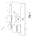
- Figure 1 is a side view of an optical assembly aligned according to present invention, and,
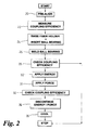
- Figure 2 is a flow diagram of a method for aligning the optical assembly of figure 1.
-
- In figure 1
optical assembly 10 is shown comprising optical fibre 4 mounted infiber holder 5. One end of the optical fibre is aligned to optical device 3.Support member 6 is disposed between the fiber holder and baseplate 1. In this embodiment thesupport member 6 is a ball bearing. However, as will be appreciated other types of support member, such as rods, can be used. Preferably, the ball bearing is fixed to the fiber holder and baseplate by resistive welding. However, as will be appreciated, other fixing methods can be used, such as laser welding. - Accurate alignment of the fibre to the optical device is achieved as follows. Rough alignment of
end 15 of the fibre to the optical device 3 is done using conventional micro alignment equipment. Thefibre holder 5 is then raised to allow the ball bearing 6 to be inserted between thefibre holder 5 and the baseplate 1 and welded in place. During welding the ball bearing collapses returning the fibre holder to its pre-aligned position before it was raised. Next accurate alignment of the fibre to the optical device is achieved by applying energy to the ball bearing. Preferably this energy is applied in a series of pulses. More preferably these pulses are current pulses. Alternatively, continuous energy is applied to the ball bearing. - During the application of energy, the ball bearing increases in temperature and becomes more ductile. Force is then applied to the ball bearing in a direction which results in an increase in the coupling efficiency of the fiber to the optical device. As will be appreciated, as a force is applied to the ball bearing, the entire fiber assemble 7 may move in response to this force. When maximum coupling efficiency has been reached, the fiber and device are said to be aligned. As is well known in the art, maximum coupling efficiency can be determined by powering the optical device and monitoring the power of the light output from the fibre.
- As will be appreciated, other criteria may be used to determine when the fiber and device are aligned, such as minimum coupling loss between a fibre and a waveguide or between two waveguides.
- Once the fiber and device are deemed to be aligned the energy and force are discontinued and the ball bearing is allowed to return to ambient temperature. During the return to ambient temperature, the position of the ball bearing and hence the alignment of the fibre to the laser will not change. Preferably, the return to ambient temperature is achieved as the energy being applied to the ball bearing is decreased. This can be done by ramping down the current driving the source of the energy.
- The force applied to the ball bearing during the application of energy is preferably a physical force and is achieved with known micro-positioning equipment.
- As shown in figure 2, the steps involved in aligning an optical fiber to an optical device can be summarised as follows. The fibre is pre-align to the optical device (Step 20). The coupling efficiency of the pre-aligned fiber and device is measured (Step 22). The fiber holder is raised and the ball bearing is inserted between the fibre holder and the baseplate (Step 24). The ball bearing is then welded in place (Step 26). During
Step 26 the ball bearing collapses returning the fiber holder to its pre-aligned position. The coupling efficiency is then checked again (Step 28) before proceeding with fine tuning the alignment. As will be appreciated, if the coupling efficiency at this stage is sufficient, then the alignment procedure can be stopped without the need forSteps 30 through 36. However if fine tuning is required, energy is applied to the ball bearing (Step 30). As the temperature in the ball bearing increases it becomes ductile. A force is then applied to the ball bearing or alternatively to the entire fiber assembly (Step 31). During the application of force the coupling efficiency is monitored (Step 32). Once maximum coupling efficiency is reached the application of force and energy are discontinued (Step 34). Finally, the assembly is allowed to cool (Step 36). - As will be appreciated,
Steps Step 30 may be only for a period of time sufficient to raise the temperature of the ball bearing to a point where it becomes ductile. Alternatively,Step 30 may be repeated periodical as needed to enable the ball bearing to remain ductile. Similarly, the application of force (Step 31) may be intermittent or continuous. Finally, the monitoring of the coupling efficiency (Step 32) may be intermittent or continuous. - It is not intended that the present invention be limited to the above embodiments and other modifications and variations are envisaged within the scope of the claims.
Claims (6)
- A method of aligning an optical fibre (4) to an optical device (3) comprises the steps of:pre-aligning the optical fibre to the optical device,measuring a coupling efficiency of the optical fiber to the optical device,applying energy (12) to a support means (6), said energy being sufficient to enable the support means to become ductile, andapplying a force to the support means in a direction which increases the coupling efficiency.
- A method as claimed in Claim 1, wherein the step of pre-aligning the optical fibre to the optical device includes the steps of:raising the optical fiber,inserting the support means, andwelding the support means in place.
- A method as claimed in any preceding Claim, wherein the energy is pulses of energy.
- A method as claimed in Claim 3, wherein the pulses of energy are current pulses.
- A method as claimed in any preceding Claim, wherein the support means (6) is a ball bearing .
- Optical components aligned accordingly to the method of Claims 1-5.
Priority Applications (2)
| Application Number | Priority Date | Filing Date | Title |
|---|---|---|---|
| EP01308966A EP1306707A1 (en) | 2001-10-22 | 2001-10-22 | Method for alignment of optical components |
| US10/236,306 US6739763B2 (en) | 2001-10-22 | 2002-09-06 | Method for alignment of optical components |
Applications Claiming Priority (1)
| Application Number | Priority Date | Filing Date | Title |
|---|---|---|---|
| EP01308966A EP1306707A1 (en) | 2001-10-22 | 2001-10-22 | Method for alignment of optical components |
Publications (1)
| Publication Number | Publication Date |
|---|---|
| EP1306707A1 true EP1306707A1 (en) | 2003-05-02 |
Family
ID=8182382
Family Applications (1)
| Application Number | Title | Priority Date | Filing Date |
|---|---|---|---|
| EP01308966A Withdrawn EP1306707A1 (en) | 2001-10-22 | 2001-10-22 | Method for alignment of optical components |
Country Status (2)
| Country | Link |
|---|---|
| US (1) | US6739763B2 (en) |
| EP (1) | EP1306707A1 (en) |
Families Citing this family (2)
| Publication number | Priority date | Publication date | Assignee | Title |
|---|---|---|---|---|
| CN108681001A (en) * | 2018-03-30 | 2018-10-19 | 昂纳信息技术(深圳)有限公司 | A kind of coaxial laser and coaxial laser system |
| US11329722B2 (en) | 2020-03-27 | 2022-05-10 | Relative Dynamics Incorporated | Optical terminals |
Citations (5)
| Publication number | Priority date | Publication date | Assignee | Title |
|---|---|---|---|---|
| US4778241A (en) * | 1986-03-12 | 1988-10-18 | Siemens Aktiengesellschaft | Method for attaching and adjusting the end section of a glass fiber |
| JPH04242705A (en) * | 1991-01-08 | 1992-08-31 | Fujitsu Ltd | Optical semiconductor module |
| EP0579439A1 (en) * | 1992-07-16 | 1994-01-19 | AT&T Corp. | Article that comprises a laser coupled to an optical fiber |
| US5745624A (en) * | 1996-08-23 | 1998-04-28 | The Boeing Company | Automatic alignment and locking method and apparatus for fiber optic module manufacturing |
| US6164837A (en) * | 1998-12-30 | 2000-12-26 | Mcdonnell Douglas Corporation | Integrated microelectromechanical alignment and locking apparatus and method for fiber optic module manufacturing |
Family Cites Families (5)
| Publication number | Priority date | Publication date | Assignee | Title |
|---|---|---|---|---|
| EP0562211A1 (en) * | 1992-03-25 | 1993-09-29 | International Business Machines Corporation | Self-aligning fiber couplers |
| US5231686A (en) * | 1992-07-17 | 1993-07-27 | Honeywell Inc. | Optical connector configured to facilitate active alignment of a photoelectric device with an optical fiber |
| US6435735B1 (en) * | 2000-05-23 | 2002-08-20 | Lucent Technologies Inc. | Assembling optical components |
| US6546172B2 (en) * | 2001-02-20 | 2003-04-08 | Avanti Optics Corporation | Optical device |
| US6546173B2 (en) * | 2001-02-20 | 2003-04-08 | Avanti Optics Corporation | Optical module |
-
2001
- 2001-10-22 EP EP01308966A patent/EP1306707A1/en not_active Withdrawn
-
2002
- 2002-09-06 US US10/236,306 patent/US6739763B2/en not_active Expired - Lifetime
Patent Citations (5)
| Publication number | Priority date | Publication date | Assignee | Title |
|---|---|---|---|---|
| US4778241A (en) * | 1986-03-12 | 1988-10-18 | Siemens Aktiengesellschaft | Method for attaching and adjusting the end section of a glass fiber |
| JPH04242705A (en) * | 1991-01-08 | 1992-08-31 | Fujitsu Ltd | Optical semiconductor module |
| EP0579439A1 (en) * | 1992-07-16 | 1994-01-19 | AT&T Corp. | Article that comprises a laser coupled to an optical fiber |
| US5745624A (en) * | 1996-08-23 | 1998-04-28 | The Boeing Company | Automatic alignment and locking method and apparatus for fiber optic module manufacturing |
| US6164837A (en) * | 1998-12-30 | 2000-12-26 | Mcdonnell Douglas Corporation | Integrated microelectromechanical alignment and locking apparatus and method for fiber optic module manufacturing |
Non-Patent Citations (2)
| Title |
|---|
| MUSA JOUANEH ET AL: "REAL TIME CONTROL OF THERMAL DISTRORTION DURING PULSED LASER WELDING OF OPTICAL PACKAGES", TRANSACTIONS OF THE AMERICAN SOCIETY OF MECHANICAL ENGINEERS, SERIES B: JOURNAL OF ENGINEERING FOR INDUSTRY, ASME. NEW YORK, US, vol. 118, no. 3, 1 August 1996 (1996-08-01), pages 445 - 448, XP000622451, ISSN: 0022-0817 * |
| PATENT ABSTRACTS OF JAPAN vol. 017, no. 014 (P - 1467) 11 January 1993 (1993-01-11) * |
Also Published As
| Publication number | Publication date |
|---|---|
| US20030077051A1 (en) | 2003-04-24 |
| US6739763B2 (en) | 2004-05-25 |
Similar Documents
| Publication | Publication Date | Title |
|---|---|---|
| EP0697117B1 (en) | Controlled splicing of optical fibers | |
| CA1229904A (en) | Laser-fiber positioner | |
| US4677290A (en) | Method of aligning an optical fiber with a light emitter via directing light toward light emitter acting as a detector | |
| JPH0227307A (en) | Optoelectronic apparatus having coupling between optical fiber and semiconductor laser diode | |
| JP7270084B2 (en) | Optical receptacles and optical transceivers | |
| US5560760A (en) | Method for optical and mechanically coupling optical fibers | |
| CA2572741C (en) | Packaging for a fiber-coupled optical device | |
| GB2293248A (en) | Optical waveguide component coupling using mating substrates | |
| KR970028628A (en) | Laser module including light focusing lens and fixing method thereof | |
| EP3143447A1 (en) | Demountable optical connector for optoelectronic devices | |
| JP2002014253A (en) | Optical fiber body and optical module having the same | |
| JP2016186645A (en) | Optical receptacle and optical transceiver | |
| JP2000352645A (en) | Method of aligning a photonic device to an optical fiber and packaging assembly for the photonic device | |
| US6312165B1 (en) | Manufacture of an optics package | |
| US6739763B2 (en) | Method for alignment of optical components | |
| US5146526A (en) | Laser pigtail assembly and method | |
| US6550984B2 (en) | Integrated optical component with photodetector for automated manufacturing platform | |
| JPH1168243A (en) | Optical module and optical axis adjustment method | |
| JP2005182014A (en) | Optimizing optical fiber alignment to optical output ports | |
| Unamuno et al. | Alignment and fixing of fiber optics based on electrothermal MEMS actuators | |
| JPH08297228A (en) | Optical fiber module manufacturing method | |
| Shimizu et al. | Identification system for optical fiber transmission operation lines with local-light injection and detection coupling system | |
| GB2185127A (en) | Fusion splicing optical fibres | |
| US6880984B2 (en) | Laser platform | |
| Paquet et al. | Edge coupling integrated optics packaging concept using liquid crystal element |
Legal Events
| Date | Code | Title | Description |
|---|---|---|---|
| PUAI | Public reference made under article 153(3) epc to a published international application that has entered the european phase |
Free format text: ORIGINAL CODE: 0009012 |
|
| AK | Designated contracting states |
Designated state(s): AT BE CH CY DE DK ES FI FR GB GR IE IT LI LU MC NL PT SE TR |
|
| AX | Request for extension of the european patent |
Extension state: AL LT LV MK RO SI |
|
| 17P | Request for examination filed |
Effective date: 20031103 |
|
| AKX | Designation fees paid |
Designated state(s): DE FR GB |
|
| 17Q | First examination report despatched |
Effective date: 20040226 |
|
| STAA | Information on the status of an ep patent application or granted ep patent |
Free format text: STATUS: THE APPLICATION IS DEEMED TO BE WITHDRAWN |
|
| 18D | Application deemed to be withdrawn |
Effective date: 20040708 |