EP1306701A2 - Collimator lens - Google Patents
Collimator lens Download PDFInfo
- Publication number
- EP1306701A2 EP1306701A2 EP02021898A EP02021898A EP1306701A2 EP 1306701 A2 EP1306701 A2 EP 1306701A2 EP 02021898 A EP02021898 A EP 02021898A EP 02021898 A EP02021898 A EP 02021898A EP 1306701 A2 EP1306701 A2 EP 1306701A2
- Authority
- EP
- European Patent Office
- Prior art keywords
- columnar
- lens
- glass tube
- hole
- center axis
- Prior art date
- Legal status (The legal status is an assumption and is not a legal conclusion. Google has not performed a legal analysis and makes no representation as to the accuracy of the status listed.)
- Withdrawn
Links
Images

Classifications
-
- G—PHYSICS
- G02—OPTICS
- G02B—OPTICAL ELEMENTS, SYSTEMS OR APPARATUS
- G02B6/00—Light guides; Structural details of arrangements comprising light guides and other optical elements, e.g. couplings
- G02B6/24—Coupling light guides
- G02B6/26—Optical coupling means
- G02B6/32—Optical coupling means having lens focusing means positioned between opposed fibre ends
Definitions
- the present invention relates to a collimator lens mainly used for connecting optical paths or the like in the field of optical communication.
- an optical fiber is connected to another, and for changing the direction of the optical path, optical signals emitted from an end of an optical fiber are reflected with a mirror to change their optical path, received by an end of another optical fiber, and propagated by that optical fiber.
- a light is discharged from an end of an optical fiber, and the discharged light is received by an end of another optical fiber.
- the light discharged from the end of the sending optical fiber is expanded and, if received by the end of the other optical fiber, it can be only partially received, resulting in a substantial attenuation of optical signals.
- Collimator lenses are fitted to ends of optical fibers to connect the optical fibers on the discharging side and the receiving side to increase the diameter of the light emitted from the end of an optical fiber, make the light beam parallel between the collimator lenses and focus the parallel light beam on the end of the receiving optical fiber.
- the diameter of the light beam can be increased to a few hundred ⁇ m, and the alignment of the optical path can be made relatively easy.
- collimator lenses are to be fitted to the ends of optical fibers, if their connecting end faces are oriented normal to the optical axis, the reflection loss on the end faces will be great.
- the end of the optical fiber guiding optical signals from a laser beam source or the like is normal to the optical axis, the light reflected by that end face is returned to the light source and may give rise to resonance at the source.
- the end of the optical fiber is inclined by about 8° relative to a plane normal to the optical axis, and the reflection from the end face is thereby prevented.
- the opposite surface of the collimator lens facing the end of the optical fiber is also inclined at substantially the same angle. If the end face of the optical fiber is inclined and the lens face opposite it is inclined by the same angle, these faces will become parallel to each other. If the optical fiber and the lens are equal in refractive index, the optical axis of the optical fiber and the optical axis of the lens will be in substantially the same direction even though there may be a slight discrepancy.
- the optical axis of the light coming out of the collimator lens is at some angles relative to the optical axis of the optical fiber. Since the angle of the end face of the optical fiber, that of the end face of the lens and the distance between those end faces differ from collimator to collimator, the angle of the optical axis of the light coming out of the collimator lens also differs from collimator to collimator.
- an object of the present invention is to provide a collimator lens which makes it possible to limit the direction in which the optical axis deviates within a specific plane and to accomplish alignment easily.
- a collimator lens according to the invention comprises:
- the collimator lens should have a surface or side surface formed by cutting off part of the collimator lens along the reference plane.
- the surface or side surface should be formed away from the center axis of the columnar lens by 60% or more of the radius r of the columnar lens. Even more preferably the surface or side surface should be formed away from the center axis of the columnar lens by 60% or more of but less than the radius of the columnar lens.
- the collimator lens according to the invention can further have a base plate, onto the upper surface of which is fitted the collimator lens, aligned with the surface or side surface.
- the collimator lens can have at least one hole formed from the outer circumference of the glass tube toward the columnar lens center axis along a perpendicular from one point on the columnar lens center axis down to the reference plane.
- the depth of the hole or holes from the outer circumference of the columnar lens should be less than 40% of the radius of the columnar lens.
- the collimator lens according to the invention can further have a base plate, wherein the collimator lens is fitted by coupling the hole to a stud provided vertically on the top surface of the base plate.
- a collimator lens may be manufactured according to the present invention by the following process:
- Another method for manufacturing a collimator lens according to the present invention is:
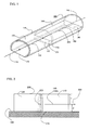
- FIG. 1 shows a perspective view of a collimator lens, which is EXAMPLE 1 of the present invention
- FIG. 2 shows a side view of the collimator lens of EXAMPLE 1 mounted on a base plate, with the glass tube omitted;
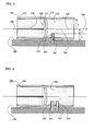
- FIG. 3 is a schematic diagram for describing the alignment of two collimator lenses of EXAMPLE 1 positioned opposite each other;
- FIG. 4 is a schematic diagram for describing the alignment of two collimator lenses of EXAMPLE 1 with a mirror between them;
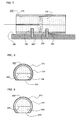
- FIG. 5 shows a longitudinal section of the collimator lens of EXAMPLE 2 mounted on a reference plane (base plate);
- FIG. 6 shows a longitudinal section of a collimator lens, which is a modification of the collimator lens of EXAMPLE 2, mounted on a reference plane (base plate);
- FIG. 7 shows a longitudinal section of a collimator lens, which is another modification of the collimator lens of EXAMPLE 2, mounted on a reference plane (base plate);
- FIG. 8 shows a section, normal to the center axis of the columnar lens, of a collimator lens which is EXAMPLE 3 of the invention.
- FIG. 9 shows a section, normal to the center axis of the columnar lens, of a collimator lens which is EXAMPLE 4 of the invention.
- FIGS. 1 through 4 A collimator lens which is EXAMPLE 1 of the invention is illustrated in FIGS. 1 through 4.
- FIG. 1 shows a perspective view of the collimator lens of EXAMPLE 1;
- FIG. 2 a side view of the collimator lens of EXAMPLE 1, with the glass tube omitted;
- FIG. 3 is a schematic diagram for illustrating the alignment of two collimator lenses of EXAMPLE 1 positioned opposite each other; and
- FIG. 4 a schematic diagram for describing the alignment of two collimator lenses of EXAMPLE 1 with a mirror between them.
- a columnar fiber chip 120 and a columnar lens 140 are arranged in a cylindrical glass tube 110 with elliptic surfaces 122 and 142, provided at one end of them, respectively, positioned opposite each other.
- the diameter of the columnar fiber chip 120 and the columnar lens 140 may be, for instance, 1 mm; that of the cylindrical glass tube 110, for instance, 1.8 mm; and the overall length of the collimator lens 100, for instance, 10 mm.
- the columnar fiber chip 120 has a through-hole 126 bored along its center axis. An optical fiber 130 is inserted into the through-hole 126, the tip of the optical fiber 130 reaching the elliptic surface 122 provided at one end of the columnar fiber chip 120.
- That end of the columnar fiber chip 120 and the tip of the optical fiber 130 are ground integrally, and the elliptic surface 122 is formed at an angle of 3 to 10° to the center axis of the fiber chip (which is concurrent with the optical axis of the optical fiber 130).
- the elliptic surface 122 is formed at an angle of 3 to 10° to the center axis
- a perpendicular from the elliptic surface 122 has an angle of 3 to 10° to the center axis. All similar expressions in the rest of this specification shall be construed in the same way, unless otherwise specified.
- the elliptic surface 142 is also formed at an angle of 3 to 10° to the center axis of the columnar lens 140.
- the angles of the elliptic surfaces 122 and 142 should preferably be about 8° to the respective center axes.
- the columnar lens 140 is arranged side by side with the columnar fiber chip 120 within the cylindrical glass tube 110 so that those elliptic surfaces 122 and 142 be parallel to and opposite each other.
- Optical signals guided within the optical fiber 130 are refracted by its end face to be discharged into the gap between the elliptic surfaces 122 and 142, refracted again by the elliptic surface 142 of the lens 140 and parallelized by the lens 140.
- the tip face of the optical fiber 130 (the same face as the elliptic surface 122) and the elliptic surface 142 of the lens 140 are exactly parallel to each other and the refractive index of the optical fiber 130 and that of the lens 140 are exactly the same, the optical axis of the optical fiber 130 and the optical axis of the parallel light beam within the lens 140 will be parallel to each other, and if the gap between the elliptic surfaces is extremely narrow, the optical axis of the optical fiber 130 and that of the parallel light beam within the lens 140 will be concurrent with each other, but these optical axes usually are not.
- the fiber chip 120 and the lens 140 it is easy to align the fiber chip 120 and the lens 140 in assembling them so that the major (longer) axes of the elliptic surface 122 of the fiber chip 120 and of the elliptic surface 142 of the lens 140 be oriented in the same direction.
- the optical axis of the optical fiber 130 and the optical axis of the parallel light beam in the lens 140 can be confined within the same plane, i.e. a plane 160 containing the major axis 123 of the elliptic surface 122 and the center axis 144 of the lens 140.
- a light 162 within the plane containing the major axis 123 of the elliptic surface 122 and the center axis 144 of the lens 140 is also refracted when it is discharged from the right side end (in FIG. 1) of the lens 140, but the axis 164 of the discharged light is also within the same plane.
- the collimator lens 100 has a reference plane 170 parallel to the plane 160 containing the major axis 123 of the elliptic surface 122 at one end of the columnar fiber chip 120 and the center axis 144 of the columnar lens 140, and a side surface is formed by cutting off part of the collimator lens along the reference plane.
- the reference plane 170 is the same as the side surface.
- FIG. 2 which is a side view of the collimator lens 100 mounted on a base plate 180, with the glass tube omitted, the distance from the center axis of the collimator lens to the side surface 170 formed by cutting off part of the collimator lens 100 is represented by d.
- the optical axis 164 of the light discharged externally from the tip face of the optical fiber 130 via the columnar lens 140 is confined within the plane 160 containing the major axis 123 of the elliptic surface 122 of the columnar fiber chip 120 and the center axis 144 of the columnar lens 140.
- the plane 160 is at a distance d from the side surface 170.
- the distance d from the center axis 144 of the columnar lens 140 to the side surface 170 should preferably be at least 60% of the radius r of the columnar lens 140. If the side surface 170 is at a distance less than 60% of the radius r, the parallel light beam passing within the columnar lens 140 will decrease and invite greater attenuation of the optical signals. Conversely, in order to provide the columnar lens 140 with a side surface, the distance d between the side surface 170 and the center axis is required to be less than the radius r. For a preferred embodiment of the invention, 0.4 mm is selected as the value of d.
- FIG. 3 Alignment of the collimator lens 100 described above and a collimator lens 100' having the same structure as the collimator lens 100 opposite each other to connect them is illustrated in a schematic diagram of FIG. 3.
- the collimator lenses 100 and 100' are arranged over the base plate 180 (whose surface is horizontal) with their side surfaces 170 and 170' aligned with each other. Since the respective axes of the collimator lenses 100 and 100' are in a plane at the distance d from the base plate 180, the optical axes of the collimator lenses 100 and 101' can be aligned by adjusting the collimator lens 100' over the base plate 180.
- the plane in which the optical axis is present is specified in the collimator lens according to the invention, alignment can be done within that plane, and the freedom is allowed on three axes, resulting in facilitated alignment.
- FIG. 4 An example in which the collimator lenses 100 and 100' are arranged with a mirror between them and aligned to be opposite each other is shown in a schematic diagram of FIG. 4.
- the collimator lenses 100 and 100' and a mirror 195 are arranged over a base plate 190.
- the mirror 195 stands vertically on the upper surface of the base plate 190.
- the emitted light from the collimator lens 100 is confined within a plane which is at the distance d from the base plate 190. Since the mirror 195 stands vertically on the base plate 190, the reflected light is also confined within a plane which is at the distance d from the base plate 190.
- the position and direction of the collimator lens 100' can be adjusted on the base plate 190.
- a side surface is formed by grinding or otherwise on each of the cylindrical glass tube 110, the columnar fiber chip 120 having the through-hole 126 bored along the center axis, the columnar lens 140 along a plane parallel to and at suitable distances from their respective center axes.
- the columnar fiber chip 120 and the columnar lens 140 can be inserted into the cylindrical glass tube 110 and assembled in advance, and the side surface 170 can be formed by grinding or otherwise in a state in which they are integrated.
- the distance d from the center axis to the side surface 170 so formed should preferably be 60% or more of the radius r of the lens 140 as explained above.
- a state in which the lens 140 is slightly shaved is desirable, and it should preferably be less than the radius.
- one end of the columnar fiber chip 120 positioned toward the tip of the optical fiber 130 is ground with reference to the side surface formed as described above in a direction normal to that side surface and at an angle of 3 to 10° to the center axis, and the elliptic surface 122 is thereby formed at that end.
- one end of the columnar lens 140 is ground to form at that end the elliptic surface 142 in a direction normal to the side surface formed as described above and at an angle of 3 to 10° to the center axis.
- the major axis of the elliptic surface 122 formed on the columnar fiber chip 120 and the center axis of the fiber chip 120 are parallel to the side surface formed in advance on the fiber chip 120, and the major axis of the elliptic surface 142 formed on the columnar lens 140 and the center axis of the lens 140 are parallel to the side surface formed in advance on the lens 140.
- the major axes of the elliptic surface 122 and the elliptic surface 142 are aligned.
- the collimator lens 100 is assembled.
- the side surface formed on each of these components is parallel to the plane containing the major axis 123 of the elliptic surface 122 and the center axis 144 of the lens 140, and the side surfaces which the components have constitute a reference plane on the side of the collimator lens 100 when the collimator lens 100 is assembled.
- FIG. 5 shows a collimator lens 200, which is EXAMPLE 2 of the present invention.
- the collimator lens 200 is provided within a cylindrical glass tube 210 with a columnar fiber chip 220 and a columnar lens 240 with elliptic surfaces 222 and 242 at one end each of the chip and the lens, respectively, arranged opposite each other.
- the columnar fiber chip 220 has a through-hole 226 bored along its center axis, an optical fiber 230 is inserted into the through-hole 226, so that one end of the optical fiber 230 reach the elliptic surface 222 at one end of the columnar fiber chip 220.
- That end of the columnar fiber chip 220 and the tip of the optical fiber 230 are integrally ground, and the elliptic surface 222 is formed at an angle of 3 to 10° to the center axis of the fiber chip (concurrent with the optical axis of the optical fiber 230).
- the elliptic surface 242 is formed at an angle of 3 to 10° to the center axis of the columnar lens 240. Preferable angles of the elliptic surfaces 222 and 242 are about 8° to the center axis.
- the major (longer) axes of the elliptic surface 222 and the elliptic surface 242 are aligned in parallel in the same direction, and therefore the axis 264 of the light ray emitted from the tip of the optical fiber 230 and parallelized by the lens 240 is confined to a plane 260 containing the major axis of the elliptic surface 222 and the center axis 244 of the lens 240.
- a plane 280 parallel to the plane 260 containing the major axis of the elliptic surface 222 and the center axis of the lens 240 is used as a reference plane for the collimator lens 200 of EXAMPLE 2.
- a columnar hole 250 along a perpendicular 246 from the center axis 244 of the columnar lens 240 to the reference plane 280 is formed from the outer circumference of the cylindrical glass tube 210 of the collimator lens 200 toward the center axis 244 of the columnar lens 240.
- This hole 250 which is normal to the reference plane, can be referred to as a reference hole.
- the distance d from the center axis 244 to the bottom of the hole 250 is 60% or more of the radius r of the columnar lens 240, i.e. its depth from the outer circumference of the columnar lens 240 is less than 40% of the radius r.
- the diameter of the cylindrical glass tube 210 is 1.8 mm and that of the columnar lens 240, 1.0 mm.
- the bore of the hole 250 if its depth from the outer circumference of the cylindrical glass tube is, for instance, 0.55 mm, will be, for instance, 0.4 mm. As the depth of the hole 250 from the outer circumference of the columnar lens 240 then is 0.15 mm, its ratio to the radius r (0.5 mm) is 30%.
- the hole 250 is described here with reference to a columnar hole by way of example, its shape may as well be a cone, a circular truncated cone or a polygonal prism.
- a columnar pin (stud) 285 stands in an appropriate position on the reference plane 280, and the columnar pin 285 is inserted into the hole 250 to fit the collimator lens 200 onto the reference plane 280.
- the height h of the columnar pin 285 from the reference plane 280 should be greater than the depth of the hole 250 from the outer circumference of the collimator lens 200.
- the collimator lens 200 can be rotated round the pin 285 while keeping the distance from the reference plane 280 to the plane 260 constant, it is possible to keep the optical axis of the collimator lens 200 at a fixed distance from the reference plane 280.
- FIG. 6 shows a collimator lens 200', which is a modification of the collimator lens 200 of EXAMPLE 2.
- the same components and parts as their respective counterparts in the collimator lens 200 are denoted by the same reference numerals.
- a similar hole 250' is bored in the lens 240 in parallel to the hole 250, and the two holes respectively engage with pins (studs) 285 and 285' standing normal to the reference plane 280. If a straight line linking the hole 250 and the hole 250' is caused to be concurrent with the direction of the optical axis of the collimator lens 200', alignment with the other collimator lens will be facilitated.
- FIG. 7 shows a longitudinal section of a collimator lens 200", which is another modification of the collimator lens 200 of EXAMPLE 2.
- the same components and parts as their respective counterparts in the collimator lens 200 are denoted by the same reference numerals.
- a similar hole 250" is bored in the columnar fiber chip 220 in parallel to the hole 250, and the two holes respectively engage with pins (studs) 285 and 285" standing normal to the reference plane 280.
- FIG. 8 shows a section, normal to the center axis of a columnar lens 340, of a collimator lens 300 which is EXAMPLE 3 of the present invention.
- This collimator lens 300 has substantially the same structure as the collimator lens 100 of EXAMPLE 1, the major difference being outer coating 312 consisting of an arc-shaped metal tube of about 0.15 mm in thickness and provided around the outer circumference of a cylindrical glass tube 310.
- the collimator lens 300 is cut off along a reference plane parallel to a plane 360 containing the major axis of the elliptic surface of a columnar fiber chip (not shown) and the center axis of the columnar lens 340 to form a side surface 370. Since the metal tube outer coating 312 is not formed on the side surface 370, the side surface 370 is directly mounted on an adjusting base plate, and alignment can be accomplished by adjusting the positions and angles of the two collimator lenses on the base plate.
- FIG. 9 shows a section, normal to the center axis of a columnar lens 440, of a collimator lens 400 which is EXAMPLE 4 of the invention.
- the collimator lens 400 has substantially the same structure as the collimator lens 100 of EXAMPLE 1, the major difference being a plated film 412 of about 3 ⁇ m in thickness formed on the outer circumference of a cylindrical glass tube 410.
- the collimator lens 400 is cut off along a reference plane parallel to a plane 460 containing the major axis of the elliptic surface of a columnar fiber chip (not shown) and the center axis of the columnar lens 440 to form a side surface 470.
- the plated film 412 of about 3 ⁇ m in thickness is also formed on this side surface, so that the side surface 470 can be used as the reference plane for alignment.
Landscapes
- Physics & Mathematics (AREA)
- General Physics & Mathematics (AREA)
- Optics & Photonics (AREA)
- Optical Couplings Of Light Guides (AREA)
Abstract
Description
Claims (10)
- A collimator lens (100) comprising:wherein the collimator lens (100) has a reference plane parallel to a plane containing a major axis of the elliptic surface (122) at one end of the columnar fiber chip (120) and a center axis of the columnar lens (140), the reference plane serving as a reference when the collimator lens (100) is to be aligned.a cylindrical glass tube (110);a columnar fiber chip (120) which is fixed within the cylindrical glass tube (110) and has a through- hole (126) along its center axis, and one end of which is an elliptic surface tilted at a predetermined angle to the center axis,an optical fiber (130) which is inserted from the other end of the fiber chip (120) into the through- hole (126), a tip of the optical fiber (130) being positioned on the elliptic surface (122); anda columnar lens (140) which has at one end an elliptic surface (142) opposite to and substantially in parallel with the elliptic surface of the fiber chip (120) and is fixed in the cylindrical glass tube (110),
- A collimator lens (100) as set forth in claim 1, having a surface formed by cutting off part of the collimator lens (100) along the reference plane.
- A collimator lens (100) as set forth in claim 2, wherein the surface is formed away from the center axis of the columnar lens (140) by 60 % or more of the radius of the columnar lens (140).
- A collimator lens (100) as set forth in claim 3, wherein the surface is formed away from the center axis of the columnar lens (140) by 60 % or more of but less than the radius of the columnar lens (140).
- A collimator lens (100) as set forth in claim 2, further having a base plate (180), onto the upper face of which is fitted the collimator lens (100), aligned with the surface (170).
- A collimator lens (200) as set forth in claim 1, having a hole (250) formed from the outer circumference of the glass tube toward the columnar lens (240) center axis along a perpendicular from one point on the columnar lens center axis down to the reference plane (170).
- A collimator lens (200) as set forth in claim 6, wherein the depth of the hole (250) from the outer circumference of the columnar lens is less than 40 % of the radius of the columnar lens (240).
- A collimator lens (200) as set forth in claim 6, further having a base plate (280), wherein the collimator lens (200) is fitted by coupling the hole to a stud (285) provided vertically on the top surface of the base plate (280).
- A method for manufacturing a collimator lens (100) comprising:partially cutting off a cylindrical glass tube, a columnar fiber chip (120) having a through- hole (126) along its center axis and a columnar lens (140) by a plane parallel to the center axis to form side surfaces on the sides of the cylindrical glass tube, the columnar fiber chip (120) and the columnar lens (140);inserting an optical fiber (130) into the through- hole (126) along the center axis of the columnar fiber chip (120) from one of the ends of the through- hole (126);grinding the other end of the columnar fiber chip (120) and one end of the columnar lens (140) to form elliptic surfaces (122, 142) having angles of 3 to 10° to the respective center axes of the columnar fiber chip (120) and the columnar lens (100) and being normal to the surfaces respectively;inserting the columnar fiber chip (120) and the columnar lens (140) into the cylindrical glass tube with the elliptic surface of the columnar fiber chip (120) and that of the columnar lens (140) positioned opposite each other; andbringing together and fixing the side surface of the cylindrical glass tube, the side surface of the columnar fiber chip (120) and the side surface of the columnar lens (140), to form on the side a surface serving as a reference plane (170) parallel to a plane containing a major axis of the elliptic surface at the other end of the columnar fiber chip (120) and a center axis of the columnar lens (140).
- A method for manufacturing a collimator lens (200) comprising:providing a cylindrical glass tube with a hole (250) formed from an outer surface of the glass tube toward a center axis of the glass tube on a side wall of the glass tube, columnar lens (240) with a hole (250), from an outer surface of the lens toward a center axis of the lens, the depth of which is less than 40 % of the radius of the lens and a columnar fiber chip (220) with a fiber (230) inserted into a through- hole (226) along a center axis of the fiber chip (220) from one end of the fiber chip (220); grinding the other end of the columnar fiber chip (220) and one end of the columnar lens (240) to form elliptic surfaces having angles of 3 to 10° to the respective center axes of the columnar fiber chip (240) and the columnar lens and being normal to the surfaces respectively;the elliptic surface formed at the one end of the columnar lens (240) being parallel to the hole of the columnar lens (240); inserting the columnar fiber chip and the columnar lens into the cylindrical glass tube with the elliptic surface of the columnar fiber chip and that of the columnar lens positioned opposite each other; andbringing together the hole of said cylindrical glass tube and the hole of the columnar lens (240) to fix the columnar fiber chip (220) and the columnar lens (240) within the cylindrical glass tube to form on the side a reference hole normal to a plane containing the major axis of the elliptic surface at the other end of the columnar fiber chip and the center axis of the columnar lens (240).
Applications Claiming Priority (2)
| Application Number | Priority Date | Filing Date | Title |
|---|---|---|---|
| JP2001314665A JP3788758B2 (en) | 2001-10-12 | 2001-10-12 | Collimator lens and collimator lens assembly |
| JP2001314665 | 2001-10-12 |
Publications (2)
| Publication Number | Publication Date |
|---|---|
| EP1306701A2 true EP1306701A2 (en) | 2003-05-02 |
| EP1306701A3 EP1306701A3 (en) | 2004-10-20 |
Family
ID=19132938
Family Applications (1)
| Application Number | Title | Priority Date | Filing Date |
|---|---|---|---|
| EP02021898A Withdrawn EP1306701A3 (en) | 2001-10-12 | 2002-10-01 | Collimator lens |
Country Status (3)
| Country | Link |
|---|---|
| US (1) | US6775070B2 (en) |
| EP (1) | EP1306701A3 (en) |
| JP (1) | JP3788758B2 (en) |
Family Cites Families (13)
| Publication number | Priority date | Publication date | Assignee | Title |
|---|---|---|---|---|
| US5071216A (en) * | 1990-06-28 | 1991-12-10 | Honeywell Inc. | Optical interconnect waveguide-beam coupler |
| US5550678A (en) * | 1994-03-14 | 1996-08-27 | Siemens Medical Systems, Inc. | Focussing collimator of the Platz-Heinzelmann type and method of making Platz-Heinzelmann type collimators |
| CA2196186A1 (en) * | 1994-07-29 | 1996-02-15 | John R. Lewis | Device for optically converting a plurality of beams |
| US6076975A (en) * | 1998-10-15 | 2000-06-20 | Molex Incorporated | Fiber optic connector assembly |
| US6246813B1 (en) * | 1999-03-01 | 2001-06-12 | Jds Uniphase Corporation | Reliable low-cost dual fiber optical collimator |
| US6168319B1 (en) * | 1999-08-05 | 2001-01-02 | Corning Incorporated | System and method for aligning optical fiber collimators |
| US6195208B1 (en) * | 1999-10-20 | 2001-02-27 | Bryan Kok Ann Ngoi | Single aspherical lens for de-astigmatism, collimation, and circulation of laser beams |
| US6469835B1 (en) * | 1999-10-28 | 2002-10-22 | Oplink Communications, Inc. | Optical collimator with long working distance |
| US6454465B1 (en) * | 2000-03-31 | 2002-09-24 | Corning Incorporated | Method of making an optical fiber collimating device |
| KR20010100868A (en) * | 2000-04-06 | 2001-11-14 | 이주하라 요죠우 | Optical write head, and method of assembling the same |
| US6377403B1 (en) * | 2000-09-07 | 2002-04-23 | David C. Smith | Short pulse laser protection fly's eye lens |
| US20020150377A1 (en) * | 2001-04-12 | 2002-10-17 | Daniel Gelbart | Method for attenuation of optical signals using reflective membrane device |
| JP4290900B2 (en) * | 2001-05-18 | 2009-07-08 | 日本ビクター株式会社 | Light source device |
-
2001
- 2001-10-12 JP JP2001314665A patent/JP3788758B2/en not_active Expired - Fee Related
-
2002
- 2002-10-01 EP EP02021898A patent/EP1306701A3/en not_active Withdrawn
- 2002-10-09 US US10/266,623 patent/US6775070B2/en not_active Expired - Fee Related
Also Published As
| Publication number | Publication date |
|---|---|
| US6775070B2 (en) | 2004-08-10 |
| EP1306701A3 (en) | 2004-10-20 |
| JP3788758B2 (en) | 2006-06-21 |
| US20030072533A1 (en) | 2003-04-17 |
| JP2003121687A (en) | 2003-04-23 |
Similar Documents
| Publication | Publication Date | Title |
|---|---|---|
| EP3084491B1 (en) | Multimode optical connector | |
| US6823109B2 (en) | Optical fiber-lens array | |
| US9625661B2 (en) | Multiple purpose optical connecting element | |
| US9897763B2 (en) | Transceiver interface having staggered cleave positions | |
| US6782162B2 (en) | Optical module and method for assembling the same | |
| US11693185B2 (en) | Optical connector with tilted mirror | |
| US4643521A (en) | Plural-channel optical rotary joint | |
| JP7698977B2 (en) | Method for manufacturing optical fiber connection structure | |
| US6775070B2 (en) | Collimator lens | |
| JP4344663B2 (en) | Optical connector | |
| JPH11160569A (en) | Optical coupling circuit | |
| US6340248B1 (en) | High precision optical collimator for optical waveguide | |
| KR100341921B1 (en) | APC Holding Jig For Polishing Ferrules Optical Connector | |
| JPH1062648A (en) | Optical fiber collimator | |
| US20250208360A1 (en) | System and apparatus for optical coupling | |
| WO2019089221A1 (en) | Tuned high-density collimator and method for tuning | |
| JP2006153941A (en) | Mode conditioner | |
| JP2004012801A (en) | Filter module |
Legal Events
| Date | Code | Title | Description |
|---|---|---|---|
| PUAI | Public reference made under article 153(3) epc to a published international application that has entered the european phase |
Free format text: ORIGINAL CODE: 0009012 |
|
| AK | Designated contracting states |
Designated state(s): AT BE BG CH CY CZ DE DK EE ES FI FR GB GR IE IT LI LU MC NL PT SE SK TR |
|
| AX | Request for extension of the european patent |
Extension state: AL LT LV MK RO SI |
|
| PUAL | Search report despatched |
Free format text: ORIGINAL CODE: 0009013 |
|
| AK | Designated contracting states |
Kind code of ref document: A3 Designated state(s): AT BE BG CH CY CZ DE DK EE ES FI FR GB GR IE IT LI LU MC NL PT SE SK TR |
|
| AX | Request for extension of the european patent |
Extension state: AL LT LV MK RO SI |
|
| AKX | Designation fees paid |
Designated state(s): DE FR IT |
|
| STAA | Information on the status of an ep patent application or granted ep patent |
Free format text: STATUS: THE APPLICATION IS DEEMED TO BE WITHDRAWN |
|
| 18D | Application deemed to be withdrawn |
Effective date: 20050421 |