EP1306677A2 - Current sensor - Google Patents
Current sensor Download PDFInfo
- Publication number
- EP1306677A2 EP1306677A2 EP02021849A EP02021849A EP1306677A2 EP 1306677 A2 EP1306677 A2 EP 1306677A2 EP 02021849 A EP02021849 A EP 02021849A EP 02021849 A EP02021849 A EP 02021849A EP 1306677 A2 EP1306677 A2 EP 1306677A2
- Authority
- EP
- European Patent Office
- Prior art keywords
- base
- sensor assembly
- detector
- circuit card
- pair
- Prior art date
- Legal status (The legal status is an assumption and is not a legal conclusion. Google has not performed a legal analysis and makes no representation as to the accuracy of the status listed.)
- Granted
Links
Images


Classifications
-
- G—PHYSICS
- G01—MEASURING; TESTING
- G01R—MEASURING ELECTRIC VARIABLES; MEASURING MAGNETIC VARIABLES
- G01R1/00—Details of instruments or arrangements of the types included in groups G01R5/00 - G01R13/00 and G01R31/00
- G01R1/02—General constructional details
-
- G—PHYSICS
- G01—MEASURING; TESTING
- G01R—MEASURING ELECTRIC VARIABLES; MEASURING MAGNETIC VARIABLES
- G01R1/00—Details of instruments or arrangements of the types included in groups G01R5/00 - G01R13/00 and G01R31/00
- G01R1/20—Modifications of basic electric elements for use in electric measuring instruments; Structural combinations of such elements with such instruments
- G01R1/22—Tong testers acting as secondary windings of current transformers
-
- G—PHYSICS
- G01—MEASURING; TESTING
- G01R—MEASURING ELECTRIC VARIABLES; MEASURING MAGNETIC VARIABLES
- G01R15/00—Details of measuring arrangements of the types provided for in groups G01R17/00 - G01R29/00, G01R33/00 - G01R33/26 or G01R35/00
- G01R15/14—Adaptations providing voltage or current isolation, e.g. for high-voltage or high-current networks
- G01R15/20—Adaptations providing voltage or current isolation, e.g. for high-voltage or high-current networks using galvano-magnetic devices, e.g. Hall-effect devices, i.e. measuring a magnetic field via the interaction between a current and a magnetic field, e.g. magneto resistive or Hall effect devices
- G01R15/207—Constructional details independent of the type of device used
Definitions
- the present invention relates to electrical component mounting and assemblies.
- Non conventional current sensors that employ a pair of magnetic field detectors have special requirements. One of these requirements is that the magnetic field detectors are parallel to one another. Another requirement may be that the electronic circuit card is disposed as closely as possible to the magnetic field detectors for purposes such as packaging, convenience and noise suppression. Furthermore, it may be advantageous to provide a current sensor assembly that may be mounted to conductors having various sizes and shapes.
- the present invention provides a current sensor assembly that maintains a pair of magnetic field detectors parallel to one another and closely disposed to an electronic circuit card. Furthermore the magnetic field detectors are selectively adjustable in order to be attached to a variety of electrical conductors.
- a sensor assembly for attachment to an electrical conductor includes a base having a cavity and a pair of detector housings extending from the base.
- the detector housings are laterally spaced and substantially parallel.
- Each of the detector housings have a cavity for receiving a magnetic field detector.
- a magnetic field detector is disposed in each of the detector housings.
- An electronic circuit card is disposed within the base cavity and is operatively coupled to the magnetic field detectors.
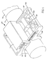
- sensor assembly 10 for attachment to an electrical conductor 5 is shown in Figure 1. More specifically, the sensor assembly 10 is attached to an insulator 7 surrounding the electrical conductor 5.
- sensor assembly 10 includes a base 20 and a pair of detector housings 30 extending from the base 20.
- the detector housings 30 each have a cavity 32 for receiving a magnetic field detector [not shown].
- a magnetic field detector is a hall sensor.
- one or both detector housings 30 may be attached directly to the base 20 or attached to the base 20 through an intermediate member (not shown) disposed between the base 20 and one of the detector housings 30.
- the detector housings 30 extend directly from the base 20.
- Figure 1 reveals one of the pair of detector housings 30 attached to a selectively extendable member 50 which extends from the base 20. The extendable member 50 cooperates with the base 20 to adjust the space between the pair of detector housings 30.
- a pair of detector housings 30 are shown extending from a base 20 and in close proximity to an electrical conductor 5.
- a pair of clamps 60 are provided for additional support. It is important that the detector housings 30 be laterally spaced and substantially parallel to one another.
- assembly 10 is shown mounted upon a bus bar 8.
- the selectively extendable member 50 enables the assembly 10 to mount upon a wide variety of electrical conductors.
- a pair of resiliently flexible ratchet members 57 having a series of teeth 58 are provided to adjust the space between the pair of detector housings 30. Adjustment of the extendable member 50 is achieved by inwardly depressing the resiliently flexible ratchet members 57 which allows one or more of the series of teeth 58 to dislodge from a contact point on the base 20, allowing the extendable member 50 to translate to and from the base 20.
- Those skilled in the art will immediately recognize that only one resiliently flexible ratchet member 57 needs to be provided in order to serve the intended purpose of fixably positioning the detector housings 30 relative to one another and for mounting the assembly 10 upon a conductor.
- FIG. 5 an exploded view of a sensor assembly 10 is shown revealing, in pertinent part, the base 20 having a cavity 22 disposed therein.
- An electronic circuit card 70 is disposed within the cavity 22.
- a cover 28 is provided to engage the base 20 to prevent dust, water and other foreign elements from entering base cavity 22 while allowing access to the contents of the cavity 22.
- a wire channel 55 extending from the selectively extendable member 50 is provided for routing a signal carrying element [not shown], such as a wire or optical cable, from a magnetic field detector disposed within the cavity 32 of the detector housing 30 to the electronic circuit card 70.
- the signal carrying element is operatively coupled to the electronic circuit card 70.
- the wire channel 55 prevents the signal carrying element from tangling when the extendable member 50 is translated to and from the base 20 as to accommodate for a variety of conductor sizes such as the bus bar 8.
- the electronic circuit card 70 may contain logic for manipulating the signals coming from the pair of magnetic field detectors, the output of which is provided through a plug connector 80.
- auxiliary circuit card 90 for communicating with the electronic circuit card 70.
- Auxiliary circuit card 90 may include additional logic.
- auxiliary circuit card 90 contains logic for detecting an arc fault.
Landscapes
- Physics & Mathematics (AREA)
- General Physics & Mathematics (AREA)
- Engineering & Computer Science (AREA)
- Power Engineering (AREA)
- Measuring Instrument Details And Bridges, And Automatic Balancing Devices (AREA)
- Investigating Or Analyzing Materials By The Use Of Electric Means (AREA)
- Measuring Fluid Pressure (AREA)
Abstract
Description
Claims (10)
- A sensor assembly (10) for attachment to an electrical conductor (5), comprising:a base (20) having a cavity (22); anda pair of detector housings (30) extending from said base (20), said detector housings (30) being laterally spaced and substantially parallel, each of said detector housings (30) having a cavity (32) for receiving a magnetic field detector.
- The sensor assembly (10) of claim 1, wherein at least one of said pair of detector housings (30) is attached to said base (20).
- The sensor assembly (10) of claim 1, wherein one of said pair of detector housings (30) is attached directly to said base (20) and the other of said pair of detector housings (30) is attached to said base (20) by an intermediate member (25).
- The sensor assembly (10) of claim 1, further comprising a selectively extendable member (50) extending from said base (20), said extendable member (50) in cooperation with said base (20) to adjust the space between said pair of detector housings (30).
- The sensor assembly (10) of claim 4, wherein said selectively extendable member (50) includes a wire channel (55).
- The sensor assembly (10) of claim 4, wherein said selectively extendable member (50) includes at least one resiliently flexible ratchet member (57) having a series of teeth (58) disposed thereon for cooperation with said base (20).
- The sensor assembly (10) of claim 1, further comprising at least one pair of jaws (60) for attaching the sensor assembly (10) to an electrical conductor (5).
- The sensor assembly (10) of claim 1, further comprising a magnetic field detector disposed in each of said detector housings (30); an electronic circuit card (70) disposed within said base cavity (22) and operatively coupled to said magnetic field detectors; and a plug connector (80) operatively connected to said electronic circuit card (70).
- The sensor assembly (10) of claim 8, further comprising an auxiliary circuit card (90) for communicating with said electronic circuit card (70).
- The sensor assembly (10) of claim 9, wherein said auxiliary circuit card (90) contains logic for detecting an arc fault.
Applications Claiming Priority (2)
| Application Number | Priority Date | Filing Date | Title |
|---|---|---|---|
| US967426 | 2001-09-28 | ||
| US09/967,426 US6642704B2 (en) | 2001-09-28 | 2001-09-28 | Device for sensing electrical current and housing therefor |
Publications (3)
| Publication Number | Publication Date |
|---|---|
| EP1306677A2 true EP1306677A2 (en) | 2003-05-02 |
| EP1306677A3 EP1306677A3 (en) | 2003-10-22 |
| EP1306677B1 EP1306677B1 (en) | 2009-04-22 |
Family
ID=25512781
Family Applications (1)
| Application Number | Title | Priority Date | Filing Date |
|---|---|---|---|
| EP02021849A Expired - Lifetime EP1306677B1 (en) | 2001-09-28 | 2002-09-29 | Current sensor |
Country Status (9)
| Country | Link |
|---|---|
| US (1) | US6642704B2 (en) |
| EP (1) | EP1306677B1 (en) |
| JP (1) | JP2003149274A (en) |
| CN (1) | CN1253719C (en) |
| AT (1) | ATE429646T1 (en) |
| BR (1) | BR0204263A (en) |
| CA (1) | CA2405214C (en) |
| DE (1) | DE60232052D1 (en) |
| MX (1) | MXPA02009488A (en) |
Families Citing this family (31)
| Publication number | Priority date | Publication date | Assignee | Title |
|---|---|---|---|---|
| US6731105B1 (en) * | 2002-09-03 | 2004-05-04 | Lockheed Martin Corporation | Current sensor with correction for transverse installation misalignment |
| EP1450176A1 (en) * | 2003-02-21 | 2004-08-25 | Liaisons Electroniques-Mecaniques Lem S.A. | Magnetic field sensor and electrical current sensor therewith |
| WO2005033716A1 (en) | 2003-10-01 | 2005-04-14 | Eaton Corporation | System and method for current sensing using anti-differential, error correcting current sensing |
| US7301344B2 (en) | 2003-11-24 | 2007-11-27 | E.I. Du Pont De Nemours & Co. | Q-damping circuit including a high temperature superconductor coil for damping a high temperature superconductor self-resonant coil in a nuclear quadrupole resonance detection system |
| JP2005218219A (en) * | 2004-01-29 | 2005-08-11 | Mitsubishi Electric Corp | Hall IC type current sensor for in-vehicle power converter |
| EP1617228B1 (en) * | 2004-07-16 | 2008-10-22 | Liaisons Electroniques-Mecaniques Lem S.A. | Current sensor |
| US7253602B2 (en) | 2004-10-12 | 2007-08-07 | Eaton Corporation | Self-powered power bus sensor employing wireless communication |
| US7145322B2 (en) * | 2004-10-12 | 2006-12-05 | Eaton Corporation | Self-powered power bus sensor employing wireless communication |
| US7477501B2 (en) * | 2005-06-02 | 2009-01-13 | Liebert Corporation | System and method of mounting current transducers in proximity to circuit breakers |
| EP1862767B1 (en) * | 2006-06-01 | 2015-05-27 | Pilz Auslandsbeteiligungen GmbH | Safety positioning sensor for cylinder, cylinders with such a positioning sensor |
| US7493221B2 (en) * | 2006-09-28 | 2009-02-17 | General Electric Company | System for power sub-metering |
| US7667482B2 (en) * | 2007-09-21 | 2010-02-23 | Eaton Corporation | Inductively powered power bus apparatus |
| US8831787B2 (en) * | 2007-11-26 | 2014-09-09 | Safeworks, Llc | Power sensor |
| US7909508B2 (en) * | 2007-12-04 | 2011-03-22 | Eaton Corporation | Sensor assembly for a power bus |
| US7843189B2 (en) * | 2008-12-18 | 2010-11-30 | General Electric Company | Current sensor having coil mounted to current carrying bus and related system |
| DE102009017230B3 (en) | 2009-04-09 | 2010-08-05 | Epcos Ag | Sensor arrangement and measuring arrangement |
| DE102009059012B4 (en) * | 2009-12-17 | 2012-08-16 | Phoenix Contact Gmbh & Co. Kg | Device for releasably securing a conductor to a current transformer housing |
| US20120146165A1 (en) * | 2010-12-09 | 2012-06-14 | Udo Ausserlechner | Magnetic field current sensors |
| JP5544500B2 (en) * | 2011-01-18 | 2014-07-09 | アルプス・グリーンデバイス株式会社 | Current sensor |
| US9093867B2 (en) | 2011-09-23 | 2015-07-28 | Eaton Corporation | Power system including an electret for a power bus |
| US8791831B2 (en) | 2011-09-23 | 2014-07-29 | Eaton Corporation | System including an indicator responsive to an electret for a power bus |
| EP2766222B1 (en) * | 2011-10-12 | 2022-06-08 | Cequent Performance Products, Inc. | Current sensing electrical converter |
| DE102012202826A1 (en) * | 2012-02-24 | 2013-08-29 | Robert Bosch Gmbh | Current sensor for mounting on a busbar |
| US9279780B2 (en) * | 2012-04-30 | 2016-03-08 | Cummins Filtration Ip, Inc. | Filters, filter assemblies, filter systems and methods for identifying installation of qualified filter elements |
| EP2660611A1 (en) * | 2012-04-30 | 2013-11-06 | LEM Intellectual Property SA | Electrical current transducer module |
| DE102013220403B4 (en) * | 2013-10-10 | 2025-02-13 | Robert Bosch Gmbh | Device and method for condition detection |
| US9651587B2 (en) | 2014-04-25 | 2017-05-16 | Eaton Corporation | Apparatus including electrodes, a rectifier or circuit, and an illuminated or non-illuminated indicator for visual indication of energized electrical conductors |
| JP2021036199A (en) * | 2017-10-06 | 2021-03-04 | 株式会社村田製作所 | Magnetic sensor and current sensor |
| KR102139639B1 (en) | 2018-05-24 | 2020-07-29 | (주)엠씨케이테크 | GRAPHENE TRANSPARENT ELECTRODE AND LCoS BASED WAVELENGTH SELECTIVE SWITCH COMPRISING THE SAME |
| US11349265B2 (en) * | 2020-09-14 | 2022-05-31 | Infineon Technologies Ag | Magnetic current sensor integration into high current connector device |
| PL4009056T3 (en) * | 2020-12-01 | 2025-01-20 | Abb Schweiz Ag | Wireless sensing device |
Family Cites Families (6)
| Publication number | Priority date | Publication date | Assignee | Title |
|---|---|---|---|---|
| US4059798A (en) * | 1976-03-08 | 1977-11-22 | F. W. Bell, Inc. | Method and apparatus for measuring the current flowing in a workpiece |
| US4258348A (en) * | 1979-11-13 | 1981-03-24 | Stb Transformer Company | Current measuring transformer |
| US5124642A (en) * | 1989-12-21 | 1992-06-23 | Sigma Instruments, Inc. | Power line post insulator with dual inductor current sensor |
| US5397982A (en) * | 1992-09-25 | 1995-03-14 | Cooper Industries, Inc. | Releasable sensor for conductor fault detection including a rigid trigger arm |
| US5552700A (en) * | 1994-09-30 | 1996-09-03 | Stanley Electric Co., Ltd. | Current detecting device with a core having an integrally fixed engaging member |
| JP3010422B2 (en) * | 1995-09-20 | 2000-02-21 | 矢崎総業株式会社 | Busbar structure of electrical junction box |
-
2001
- 2001-09-28 US US09/967,426 patent/US6642704B2/en not_active Expired - Fee Related
-
2002
- 2002-09-25 CA CA2405214A patent/CA2405214C/en not_active Expired - Lifetime
- 2002-09-26 BR BR0204263-0A patent/BR0204263A/en not_active Application Discontinuation
- 2002-09-27 JP JP2002283496A patent/JP2003149274A/en active Pending
- 2002-09-27 MX MXPA02009488A patent/MXPA02009488A/en active IP Right Grant
- 2002-09-28 CN CNB021469946A patent/CN1253719C/en not_active Expired - Lifetime
- 2002-09-29 DE DE60232052T patent/DE60232052D1/en not_active Expired - Lifetime
- 2002-09-29 EP EP02021849A patent/EP1306677B1/en not_active Expired - Lifetime
- 2002-09-29 AT AT02021849T patent/ATE429646T1/en not_active IP Right Cessation
Also Published As
| Publication number | Publication date |
|---|---|
| ATE429646T1 (en) | 2009-05-15 |
| US20030062886A1 (en) | 2003-04-03 |
| CN1409120A (en) | 2003-04-09 |
| JP2003149274A (en) | 2003-05-21 |
| CA2405214C (en) | 2012-03-13 |
| BR0204263A (en) | 2003-09-16 |
| EP1306677A3 (en) | 2003-10-22 |
| DE60232052D1 (en) | 2009-06-04 |
| CN1253719C (en) | 2006-04-26 |
| CA2405214A1 (en) | 2003-03-28 |
| MXPA02009488A (en) | 2003-04-03 |
| EP1306677B1 (en) | 2009-04-22 |
| US6642704B2 (en) | 2003-11-04 |
Similar Documents
| Publication | Publication Date | Title |
|---|---|---|
| US6642704B2 (en) | Device for sensing electrical current and housing therefor | |
| US6515468B1 (en) | Current sensor and electric circuit using the same | |
| JP3010422B2 (en) | Busbar structure of electrical junction box | |
| US5583429A (en) | Current detection device | |
| EP2782195B1 (en) | Connector and connector assembly | |
| US9431776B2 (en) | Connector | |
| JP2001066327A (en) | Current sensor | |
| JP3211939B2 (en) | Electrical junction box | |
| JP5173768B2 (en) | Current detector | |
| JP2004517326A (en) | Equipment, current measuring instrument and automobile | |
| JP2011232246A (en) | Current detector | |
| US10153634B2 (en) | Switch box and overcurrent preventing method | |
| WO2009151011A1 (en) | Current sensor | |
| JP2022519060A (en) | Current transducer with magnetic field detector module | |
| JP3760805B2 (en) | On-board current sensor | |
| US6917193B1 (en) | Distance tolerant leadless current sensor | |
| US5548208A (en) | Terminal for connecting live conductors | |
| JP4514124B2 (en) | Plug unit with built-in current detector | |
| JP2003139803A (en) | Current detecting device and fusible link unit using the current detecting device | |
| JP3172629B2 (en) | Current / voltage detector | |
| JPH01244698A (en) | Cabinet for electric apparatus | |
| JP2002189038A (en) | Electric wire with current detector, current detector and method of assembling current detector to electric wire | |
| JPH0979864A (en) | Rotational position detector | |
| JP2006145238A (en) | Current sensor | |
| JPS5844334Y2 (en) | Electrical connection device for vehicle instruments |
Legal Events
| Date | Code | Title | Description |
|---|---|---|---|
| PUAI | Public reference made under article 153(3) epc to a published international application that has entered the european phase |
Free format text: ORIGINAL CODE: 0009012 |
|
| AK | Designated contracting states |
Designated state(s): AT BE BG CH CY CZ DE DK EE ES FI FR GB GR IE IT LI LU MC NL PT SE SK TR |
|
| AX | Request for extension of the european patent |
Extension state: AL LT LV MK RO SI |
|
| PUAL | Search report despatched |
Free format text: ORIGINAL CODE: 0009013 |
|
| AK | Designated contracting states |
Kind code of ref document: A3 Designated state(s): AT BE BG CH CY CZ DE DK EE ES FI FR GB GR IE IT LI LU MC NL PT SE SK TR |
|
| AX | Request for extension of the european patent |
Extension state: AL LT LV MK RO SI |
|
| RIC1 | Information provided on ipc code assigned before grant |
Ipc: 7G 01R 15/18 A Ipc: 7G 01R 19/00 B Ipc: 7G 01R 1/04 B |
|
| 17P | Request for examination filed |
Effective date: 20040421 |
|
| AKX | Designation fees paid |
Designated state(s): AT BE BG CH CY CZ DE DK EE ES FI FR GB GR IE IT LI LU MC NL PT SE SK TR |
|
| 17Q | First examination report despatched |
Effective date: 20061103 |
|
| GRAP | Despatch of communication of intention to grant a patent |
Free format text: ORIGINAL CODE: EPIDOSNIGR1 |
|
| GRAS | Grant fee paid |
Free format text: ORIGINAL CODE: EPIDOSNIGR3 |
|
| GRAA | (expected) grant |
Free format text: ORIGINAL CODE: 0009210 |
|
| AK | Designated contracting states |
Kind code of ref document: B1 Designated state(s): AT BE BG CH CY CZ DE DK EE ES FI FR GB GR IE IT LI LU MC NL PT SE SK TR |
|
| REG | Reference to a national code |
Ref country code: GB Ref legal event code: FG4D |
|
| REG | Reference to a national code |
Ref country code: CH Ref legal event code: EP |
|
| REG | Reference to a national code |
Ref country code: IE Ref legal event code: FG4D |
|
| REF | Corresponds to: |
Ref document number: 60232052 Country of ref document: DE Date of ref document: 20090604 Kind code of ref document: P |
|
| NLV1 | Nl: lapsed or annulled due to failure to fulfill the requirements of art. 29p and 29m of the patents act | ||
| PG25 | Lapsed in a contracting state [announced via postgrant information from national office to epo] |
Ref country code: FI Free format text: LAPSE BECAUSE OF FAILURE TO SUBMIT A TRANSLATION OF THE DESCRIPTION OR TO PAY THE FEE WITHIN THE PRESCRIBED TIME-LIMIT Effective date: 20090422 Ref country code: ES Free format text: LAPSE BECAUSE OF FAILURE TO SUBMIT A TRANSLATION OF THE DESCRIPTION OR TO PAY THE FEE WITHIN THE PRESCRIBED TIME-LIMIT Effective date: 20090802 Ref country code: AT Free format text: LAPSE BECAUSE OF FAILURE TO SUBMIT A TRANSLATION OF THE DESCRIPTION OR TO PAY THE FEE WITHIN THE PRESCRIBED TIME-LIMIT Effective date: 20090422 Ref country code: PT Free format text: LAPSE BECAUSE OF FAILURE TO SUBMIT A TRANSLATION OF THE DESCRIPTION OR TO PAY THE FEE WITHIN THE PRESCRIBED TIME-LIMIT Effective date: 20090822 |
|
| PG25 | Lapsed in a contracting state [announced via postgrant information from national office to epo] |
Ref country code: SE Free format text: LAPSE BECAUSE OF FAILURE TO SUBMIT A TRANSLATION OF THE DESCRIPTION OR TO PAY THE FEE WITHIN THE PRESCRIBED TIME-LIMIT Effective date: 20090722 Ref country code: NL Free format text: LAPSE BECAUSE OF FAILURE TO SUBMIT A TRANSLATION OF THE DESCRIPTION OR TO PAY THE FEE WITHIN THE PRESCRIBED TIME-LIMIT Effective date: 20090422 |
|
| PG25 | Lapsed in a contracting state [announced via postgrant information from national office to epo] |
Ref country code: EE Free format text: LAPSE BECAUSE OF FAILURE TO SUBMIT A TRANSLATION OF THE DESCRIPTION OR TO PAY THE FEE WITHIN THE PRESCRIBED TIME-LIMIT Effective date: 20090422 Ref country code: DK Free format text: LAPSE BECAUSE OF FAILURE TO SUBMIT A TRANSLATION OF THE DESCRIPTION OR TO PAY THE FEE WITHIN THE PRESCRIBED TIME-LIMIT Effective date: 20090422 Ref country code: CZ Free format text: LAPSE BECAUSE OF FAILURE TO SUBMIT A TRANSLATION OF THE DESCRIPTION OR TO PAY THE FEE WITHIN THE PRESCRIBED TIME-LIMIT Effective date: 20090422 |
|
| PG25 | Lapsed in a contracting state [announced via postgrant information from national office to epo] |
Ref country code: BE Free format text: LAPSE BECAUSE OF FAILURE TO SUBMIT A TRANSLATION OF THE DESCRIPTION OR TO PAY THE FEE WITHIN THE PRESCRIBED TIME-LIMIT Effective date: 20090422 Ref country code: SK Free format text: LAPSE BECAUSE OF FAILURE TO SUBMIT A TRANSLATION OF THE DESCRIPTION OR TO PAY THE FEE WITHIN THE PRESCRIBED TIME-LIMIT Effective date: 20090422 |
|
| PLBE | No opposition filed within time limit |
Free format text: ORIGINAL CODE: 0009261 |
|
| STAA | Information on the status of an ep patent application or granted ep patent |
Free format text: STATUS: NO OPPOSITION FILED WITHIN TIME LIMIT |
|
| 26N | No opposition filed |
Effective date: 20100125 |
|
| PG25 | Lapsed in a contracting state [announced via postgrant information from national office to epo] |
Ref country code: BG Free format text: LAPSE BECAUSE OF FAILURE TO SUBMIT A TRANSLATION OF THE DESCRIPTION OR TO PAY THE FEE WITHIN THE PRESCRIBED TIME-LIMIT Effective date: 20090722 |
|
| PG25 | Lapsed in a contracting state [announced via postgrant information from national office to epo] |
Ref country code: MC Free format text: LAPSE BECAUSE OF NON-PAYMENT OF DUE FEES Effective date: 20090930 |
|
| REG | Reference to a national code |
Ref country code: CH Ref legal event code: PL |
|
| REG | Reference to a national code |
Ref country code: IE Ref legal event code: MM4A |
|
| PG25 | Lapsed in a contracting state [announced via postgrant information from national office to epo] |
Ref country code: IE Free format text: LAPSE BECAUSE OF NON-PAYMENT OF DUE FEES Effective date: 20090929 |
|
| PG25 | Lapsed in a contracting state [announced via postgrant information from national office to epo] |
Ref country code: CH Free format text: LAPSE BECAUSE OF NON-PAYMENT OF DUE FEES Effective date: 20090930 Ref country code: GR Free format text: LAPSE BECAUSE OF FAILURE TO SUBMIT A TRANSLATION OF THE DESCRIPTION OR TO PAY THE FEE WITHIN THE PRESCRIBED TIME-LIMIT Effective date: 20090723 Ref country code: LI Free format text: LAPSE BECAUSE OF NON-PAYMENT OF DUE FEES Effective date: 20090930 |
|
| PG25 | Lapsed in a contracting state [announced via postgrant information from national office to epo] |
Ref country code: LU Free format text: LAPSE BECAUSE OF NON-PAYMENT OF DUE FEES Effective date: 20090929 |
|
| PG25 | Lapsed in a contracting state [announced via postgrant information from national office to epo] |
Ref country code: TR Free format text: LAPSE BECAUSE OF FAILURE TO SUBMIT A TRANSLATION OF THE DESCRIPTION OR TO PAY THE FEE WITHIN THE PRESCRIBED TIME-LIMIT Effective date: 20090422 |
|
| PG25 | Lapsed in a contracting state [announced via postgrant information from national office to epo] |
Ref country code: CY Free format text: LAPSE BECAUSE OF FAILURE TO SUBMIT A TRANSLATION OF THE DESCRIPTION OR TO PAY THE FEE WITHIN THE PRESCRIBED TIME-LIMIT Effective date: 20090422 |
|
| REG | Reference to a national code |
Ref country code: FR Ref legal event code: PLFP Year of fee payment: 15 |
|
| REG | Reference to a national code |
Ref country code: FR Ref legal event code: PLFP Year of fee payment: 16 |
|
| REG | Reference to a national code |
Ref country code: FR Ref legal event code: PLFP Year of fee payment: 17 |
|
| REG | Reference to a national code |
Ref country code: GB Ref legal event code: 732E Free format text: REGISTERED BETWEEN 20181115 AND 20181130 |
|
| REG | Reference to a national code |
Ref country code: DE Ref legal event code: R082 Ref document number: 60232052 Country of ref document: DE Ref country code: DE Ref legal event code: R081 Ref document number: 60232052 Country of ref document: DE Owner name: EATON INTELLIGENT POWER LIMITED, IE Free format text: FORMER OWNER: EATON CORP., CLEVELAND, OHIO, US |
|
| PGFP | Annual fee paid to national office [announced via postgrant information from national office to epo] |
Ref country code: IT Payment date: 20210824 Year of fee payment: 20 Ref country code: FR Payment date: 20210819 Year of fee payment: 20 |
|
| PGFP | Annual fee paid to national office [announced via postgrant information from national office to epo] |
Ref country code: GB Payment date: 20210820 Year of fee payment: 20 Ref country code: DE Payment date: 20210818 Year of fee payment: 20 |
|
| REG | Reference to a national code |
Ref country code: DE Ref legal event code: R071 Ref document number: 60232052 Country of ref document: DE |
|
| REG | Reference to a national code |
Ref country code: GB Ref legal event code: PE20 Expiry date: 20220928 |
|
| PG25 | Lapsed in a contracting state [announced via postgrant information from national office to epo] |
Ref country code: GB Free format text: LAPSE BECAUSE OF EXPIRATION OF PROTECTION Effective date: 20220928 |
|
| P01 | Opt-out of the competence of the unified patent court (upc) registered |
Effective date: 20230521 |