EP1306460A2 - Metal matrix composite structure - Google Patents
Metal matrix composite structure Download PDFInfo
- Publication number
- EP1306460A2 EP1306460A2 EP02024456A EP02024456A EP1306460A2 EP 1306460 A2 EP1306460 A2 EP 1306460A2 EP 02024456 A EP02024456 A EP 02024456A EP 02024456 A EP02024456 A EP 02024456A EP 1306460 A2 EP1306460 A2 EP 1306460A2
- Authority
- EP
- European Patent Office
- Prior art keywords
- reinforcing fibers
- joined
- flat
- metal
- hot
- Prior art date
- Legal status (The legal status is an assumption and is not a legal conclusion. Google has not performed a legal analysis and makes no representation as to the accuracy of the status listed.)
- Withdrawn
Links
Images

Classifications
-
- C—CHEMISTRY; METALLURGY
- C22—METALLURGY; FERROUS OR NON-FERROUS ALLOYS; TREATMENT OF ALLOYS OR NON-FERROUS METALS
- C22C—ALLOYS
- C22C47/00—Making alloys containing metallic or non-metallic fibres or filaments
- C22C47/02—Pretreatment of the fibres or filaments
- C22C47/025—Aligning or orienting the fibres
-
- C—CHEMISTRY; METALLURGY
- C22—METALLURGY; FERROUS OR NON-FERROUS ALLOYS; TREATMENT OF ALLOYS OR NON-FERROUS METALS
- C22C—ALLOYS
- C22C47/00—Making alloys containing metallic or non-metallic fibres or filaments
- C22C47/02—Pretreatment of the fibres or filaments
- C22C47/06—Pretreatment of the fibres or filaments by forming the fibres or filaments into a preformed structure, e.g. using a temporary binder to form a mat-like element
-
- C—CHEMISTRY; METALLURGY
- C22—METALLURGY; FERROUS OR NON-FERROUS ALLOYS; TREATMENT OF ALLOYS OR NON-FERROUS METALS
- C22C—ALLOYS
- C22C47/00—Making alloys containing metallic or non-metallic fibres or filaments
- C22C47/20—Making alloys containing metallic or non-metallic fibres or filaments by subjecting to pressure and heat an assembly comprising at least one metal layer or sheet and one layer of fibres or filaments
-
- B—PERFORMING OPERATIONS; TRANSPORTING
- B22—CASTING; POWDER METALLURGY
- B22F—WORKING METALLIC POWDER; MANUFACTURE OF ARTICLES FROM METALLIC POWDER; MAKING METALLIC POWDER; APPARATUS OR DEVICES SPECIALLY ADAPTED FOR METALLIC POWDER
- B22F2998/00—Supplementary information concerning processes or compositions relating to powder metallurgy
-
- B—PERFORMING OPERATIONS; TRANSPORTING
- B22—CASTING; POWDER METALLURGY
- B22F—WORKING METALLIC POWDER; MANUFACTURE OF ARTICLES FROM METALLIC POWDER; MAKING METALLIC POWDER; APPARATUS OR DEVICES SPECIALLY ADAPTED FOR METALLIC POWDER
- B22F2999/00—Aspects linked to processes or compositions used in powder metallurgy
-
- Y—GENERAL TAGGING OF NEW TECHNOLOGICAL DEVELOPMENTS; GENERAL TAGGING OF CROSS-SECTIONAL TECHNOLOGIES SPANNING OVER SEVERAL SECTIONS OF THE IPC; TECHNICAL SUBJECTS COVERED BY FORMER USPC CROSS-REFERENCE ART COLLECTIONS [XRACs] AND DIGESTS
- Y10—TECHNICAL SUBJECTS COVERED BY FORMER USPC
- Y10T—TECHNICAL SUBJECTS COVERED BY FORMER US CLASSIFICATION
- Y10T428/00—Stock material or miscellaneous articles
- Y10T428/12—All metal or with adjacent metals
- Y10T428/12444—Embodying fibers interengaged or between layers [e.g., paper, etc.]
-
- Y—GENERAL TAGGING OF NEW TECHNOLOGICAL DEVELOPMENTS; GENERAL TAGGING OF CROSS-SECTIONAL TECHNOLOGIES SPANNING OVER SEVERAL SECTIONS OF THE IPC; TECHNICAL SUBJECTS COVERED BY FORMER USPC CROSS-REFERENCE ART COLLECTIONS [XRACs] AND DIGESTS
- Y10—TECHNICAL SUBJECTS COVERED BY FORMER USPC
- Y10T—TECHNICAL SUBJECTS COVERED BY FORMER US CLASSIFICATION
- Y10T428/00—Stock material or miscellaneous articles
- Y10T428/12—All metal or with adjacent metals
- Y10T428/12465—All metal or with adjacent metals having magnetic properties, or preformed fiber orientation coordinate with shape
-
- Y—GENERAL TAGGING OF NEW TECHNOLOGICAL DEVELOPMENTS; GENERAL TAGGING OF CROSS-SECTIONAL TECHNOLOGIES SPANNING OVER SEVERAL SECTIONS OF THE IPC; TECHNICAL SUBJECTS COVERED BY FORMER USPC CROSS-REFERENCE ART COLLECTIONS [XRACs] AND DIGESTS
- Y10—TECHNICAL SUBJECTS COVERED BY FORMER USPC
- Y10T—TECHNICAL SUBJECTS COVERED BY FORMER US CLASSIFICATION
- Y10T428/00—Stock material or miscellaneous articles
- Y10T428/12—All metal or with adjacent metals
- Y10T428/12486—Laterally noncoextensive components [e.g., embedded, etc.]
-
- Y—GENERAL TAGGING OF NEW TECHNOLOGICAL DEVELOPMENTS; GENERAL TAGGING OF CROSS-SECTIONAL TECHNOLOGIES SPANNING OVER SEVERAL SECTIONS OF THE IPC; TECHNICAL SUBJECTS COVERED BY FORMER USPC CROSS-REFERENCE ART COLLECTIONS [XRACs] AND DIGESTS
- Y10—TECHNICAL SUBJECTS COVERED BY FORMER USPC
- Y10T—TECHNICAL SUBJECTS COVERED BY FORMER US CLASSIFICATION
- Y10T428/00—Stock material or miscellaneous articles
- Y10T428/249921—Web or sheet containing structurally defined element or component
- Y10T428/249924—Noninterengaged fiber-containing paper-free web or sheet which is not of specified porosity
- Y10T428/249927—Fiber embedded in a metal matrix
Definitions
- the present invention relates to a composite formed by including metal matrix such as titan or titan alloy with reinforcing fiber such as carbon fiber, more particularly to a composite in which the reinforcing fibers have end parts or to a composite having joint parts.
- composites formed by combining plural materials have been used widely.
- Composites are used for parts or members used under particularly severe condition since a composite having characteristics appropriate for a specific use can fabricate by selection of materials, compositions or methods of processing.
- Metal matrix composites such as titan matrix composite(TMC) have been intensively studied and developed for parts requiring high specific strength and high specific rigidity.
- the composites are reinforced in such a way that reinforced materials typified by ceramic fibers such as silicon carbide or alumina fiber are mixed with metal matrices comprising metals or metal alloys.
- Forming preform when composing each of raw materials is the particularly important process in fabrication of the composite. The following four ways are usually employed.
- the way of composing to form preform by sandwiching bundles of reinforcing fibers between metal matrices where reinforcing fibers have been agglomerated together in advance such as a way of fixing reinforcing fibers with organic binder or a way of fixing reinforcing fibers by weaving with metal (metal alloy) foil is widely employed because of inexpensive cost and simple processing.
- HIP hot isostatic pressing
- Such HIP processing is performed as follows.
- the tape type preform is sealed into a HIP pressure vessel and set to an initial pressure and temperature.
- an initial pressure is approximately 30 kg/cm 2 and temperature is approximately 400°C.
- An appropriate temperature in case of Ti-4.5Al-3V-2Fe-2Mo alloy is approximately 750-850°C, or more preferably approximately 775°C.
- pressure is increased to approximately 1200 kg/cm 2 , the condition is kept for about 2 hours and then both of the pressure and temperature are decreased.
- An annular composite can be made by HIP processing from the convolved tape type preform thus fabricated.
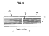
- the cutting ends 15 in the annular part involve the risk of rupture of the material itself through generation of cracks owning to repeated stress which is loaded to the composite even if the stress is under the elemental strength of the composite 16 .
- the present invention has an object to provide a metal matrix composite having stable performance without extremely weak portions and capable of assuring strength with a simple structure.
- a metal matrix composite formed by hot-pressing or hot-isostatic-pressing a flat formation of reinforcing fibers sandwiched between metal matrices comprises a joined end part in the longitudinal direction of reinforcing fibers which is joined obliquely at an aspect ratio within the approximate range of 2:1 to 1:10 on the basis of the direction of the width of reinforcing fibers to the longitudinal direction of reinforcing fibers.
- a metal matrix composite formed by hot-pressing or hot-isostatic-pressing a flat formation of reinforcing fibers sandwiched between metal matrices comprises a joined end part in the longitudinal direction of reinforcing fibers which is joined obliquely at a joining angle of 5 to 60 degrees with respect to the longitudinal direction of reinforcing fibers.
- the present invention provides a composite which is composed in such a manner that the end part of reinforcing fibers are cut in an oblique direction, the obliquely cut faces are joined together, the joined part of reinforcing fibers is sandwiched between metal matrices, and thus integrated part of metal sandwiched fibers is hot-pressed or hot-isostatic-pressed.
- a composite having stable performance and reliability, which does not give rise to lowering of strength against the stress perpendicular to the longitudinal direction of fibers can be provided.
- the metal matrix composite according to the invention can be fabricated with reduced cost because the composite have extremely simple structure.
- the joining angle is preferably 5 to 60 degrees or more preferably 5 to 45 degrees or the aspect ratio is preferably in the approximate range of 2:1 to 1:10.
- the ratio difference of the aspect ratio is larger than about 1:10 or the joining angle is less than about 5 degrees, the strength of the reinforcing fibers in themselves lowers, if the ratio difference of the aspect ratio is smaller than about 2:1 or the joining angle is greater than about 60 degrees, the overlap length of the joined part is so short that the fact causes lowering of strength of the reinforcing fibers.
- a plurality of metal matrices and a plurality flat formations of reinforcing fibers are lapped each other to form layers of metal matrices and flat formations of reinforcing fibers so that the adjacent upper layers of flat formations of reinforcing fibers and the adjacent lower layers of flat formations of reinforcing fibers to a layer having a joined part of flat formations of reinforcing fibers are continuous and have no joined parts.
- the joined part position should be a middle position with respect to the lapping direction so as to be protected by the upper and lower layers of continuous reinforcing fibers, preventing from lowering of strength. Thus, more reliable quality assurance is possible.
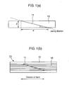
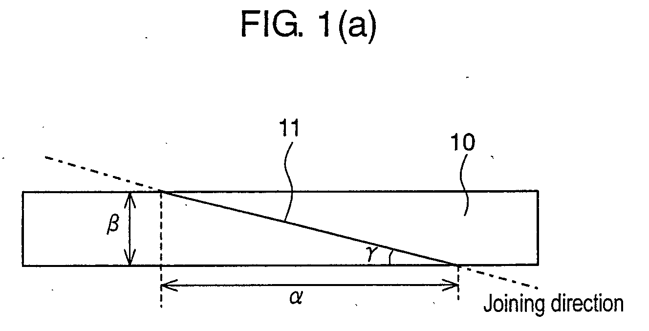
- Fig. 1 is a schematic side view of composite material tape having an oblique joint ends part according to an embodiment of the present invention.
- Fig. 2 is a schematic drawing showing lapping structure of composite material tape according to an embodiment of the present invention.
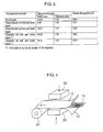
- Fig. 3 is a table showing tensile strength of an obliquely cutting end part, of perpendicularly cutting end part and of no end part of composite material tape according to an embodiment of the present invention.
- Fig. 4 is a schematic perspective view showing heat press process of composite material tape.
- Fig. 5 is a schematic side view of a joined end part of conventional composite material tape.
- a flat formation of reinforcing fibers 10 is formed by weaving reinforcing fibers consisting essentially of silicon carbide and is aggregate of discontinuous reinforcing fibers after removal of defective parts or after fabricating process. Meanwhile, titan alloy foil 12 is formed to continuous tape form.
- titan alloy is used as matrix and silicon carbide is used as reinforcing fiber
- material used is not particularly restricted.
- metal or metal alloy as aluminum, stainless can be used instead of titan alloy foil 12 and such fiber as ceramic fiber including alumina fiber can be used instead of silicon carbide fiber. Any thing such as a flat formation formed by aligning silicon carbide fibers in one direction and fixing with organic binder will do when it comes to a flat formation of reinforcing fibers instead of a flat formation of reinforcing fibers 10.
- reinforcing fibers 10 is processed to a tape type preform 13 in such a manner that obliquely cut discontinuous part of reinforcing fibers is sandwiched between titan alloy foils 12 .
- a joined part 11 of the flat formation of reinforcing fibers 10 is formed as shown in Fig. 1(a), so that an aspect ratio ⁇ : ⁇ of the length ⁇ in the longitudinal direction of reinforcing fibers to the length ⁇ in the direction of width of reinforcing fibers is approximately 2:1 to 1:10 or a joining angle ⁇ with respect to the longitudinal direction of reinforcing fibers is to be approximately 5-60 degrees.
- a continuous composite material tape is fabricated by sandwiching thus formed flat formation of reinforcing fibers 10 , as shown in Fig. 4, between the titan alloy foils 12, pressing vertically with a hot press 20 to compose, and taking up to a roll 21.
- Fig. 2(a) and Fig. 2(b) show composite material tapes 14a, 14b fabricated by lapping a plurality of flat formations of reinforcing fibers 10 and a plurality of titan alloy foils 12.
- the table of Fig. 3 shows a measured results of the tensile strength of the composite material tapes 14a, 14b.
- Fig. 2(a) shows a composite material tape 14a having a joined part 11 in the flat formation of reinforcing fibers 10a which is the nearest to the surface out of a plurality of flat formations of reinforcing fibers 10A.
- Fig. 2(b) shows a composite material tape 14b having a joined part 11 in the flat formation of reinforcing fibers 10b which is the inner part in the direction of lapping, i.e. in the direction of width of the composite material out of a plurality of flat formations of reinforcing fibers 10B so that the outer flat formation of reinforcing fibers 10a in the upper and lower direction is a continuous without joined parts which is the composite material tape 14b.
- These composite material are hot-pressed, set to a predetermined form, and applied HIP processing.
- the table of Fig. 3 shows a measured results of the tensile strength of a composite material having a obliquely joined ends part shown in Figs. 2(a) and (b), of a composite material having no obliquely joined ends part, and of a composite material having a vertically joined ends part, each fabricated under the same condition as the former.
- the filling factor of reinforcing fibers that is contained in the composite materials is the same respectively.
- temperature and pressure condition of measurement is the same.
- test specimen of composite material used in such measurement is 10 mm wide, 1.6 mm thick.
- a tensile strength of the specimen is measured in the longitudinal direction of the fibers at atmospheric pressure and ordinary temperature (about 24 °C).
- the observed tensile strength of a composite material having no end part (6 ply of preforms of reinforcing fibers) is 1609 N/mm 2
- the observed tensile strength of a composite material having a vertical end part (7 ply of preforms of reinforcing fibers) at the inner part is 1517 N/mm 2 though more ply of preforms of reinforcing fibers should have strengthen the composite and yet the observed tensile strength of a composite material having a vertical end part (6 ply of preforms of reinforcing fibers) at the outer part is as weak as 1292 N/mm 2 .
- a composite material 14a (6 ply) having a obliquely joined end part 11 of a joining angle of 45 degrees at the outer part, as shown in Fig. 2(a), shows a tensile strength of 1610 N/mm 2 , being inferior to the composite material 14b having joined end part at the inner part with regard to its strength but bringing about no significant lowering of strength.
- the obliquely joined end part 11 is nearly as strong as the no joined end part; thereby the composite material has no part that gives rise to lowering of strength, which results in securing reliability of the material.
- a composite material having increased reliability can be provided when the joined part position is a middle position with respect to the lapping direction so as to be protected by the upper and lower layers of continuous reinforcing fibers, preventing from lowering of strength.
- the feature of the present invention can be applied when a plurality of formation formed preforms made by hot-pressing reinforcing fibers vapor-deposited with metal matrix are further lapped and hot-isostaic-pressed to fabricate a composite material.
- a composite material without lowering of strength can be provided if the preforms are lapped in such a manner that joined parts of the preformes are oblique.
- a metal matrix composite having stable performance without extremely lowering the strength against the stress perpendicular to the longitudinal direction of fibers and capable of assuring strength with a simple structure can be provide.
- the strength of the composite material is not lowered because of joining with an aspect ratio of within an approximate range of 2:1 to 1:10 or with a joining angle of 5 to 60 degrees and by lapping with enough overlap of joined parts.
- the joined part position is a middle position with respect to the lapping direction so as to be protected by the upper and lower layers of continuous reinforcing fibers, preventing from lowering of strength and thus, more reliable quality assurance being possible.
- the metal matrix composite according to the invention can be fabricated with reduced cost because the composite has extremely simple structure.
Landscapes
- Chemical & Material Sciences (AREA)
- Engineering & Computer Science (AREA)
- Materials Engineering (AREA)
- Mechanical Engineering (AREA)
- Metallurgy (AREA)
- Organic Chemistry (AREA)
- Crystallography & Structural Chemistry (AREA)
- Manufacture Of Alloys Or Alloy Compounds (AREA)
- Pressure Welding/Diffusion-Bonding (AREA)
Abstract
Description
Claims (3)
- A metal matrix composite formed by hot-pressing or hot-isostatic-pressing a flat formation of reinforcing fibers sandwiched between metal matrices comprising a joined end part in the longitudinal direction of reinforcing fibers which is joined obliquely at an aspect ratio within the approximate range of 2:1 to 1:10 on the basis of the direction of the width of reinforcing fibers to the longitudinal direction of reinforcing fibers.
- A metal matrix composite formed by hot-pressing or hot-isostatic-pressing a flat formation of reinforcing fibers sandwiched between metal matrices comprising a joined end part in the longitudinal direction of reinforcing fibers which is joined obliquely at a joining angle of about 5 to 60 degrees with respect to the longitudinal direction of reinforcing fibers.
- A metal matrix composite formed by hot-pressing or hot-isostatic-pressing a flat formation of reinforcing fibers sandwiched between metal matrices according to claims 1 or 2, wherein a plurality of metal matrices and a plurality flat formations of reinforcing fibers are lapped each other to form layers of metal matrices and flat formations of reinforcing fibers so that the adjacent upper layers of flat formations of reinforcing fibers and the adjacent lower layers of flat formations of reinforcing fibers to a layer having a joined part of flat formations of reinforcing fibers are continuous and have no joined parts.
Applications Claiming Priority (2)
| Application Number | Priority Date | Filing Date | Title |
|---|---|---|---|
| JP2001330780A JP2003138354A (en) | 2001-10-29 | 2001-10-29 | Metal matrix composite |
| JP2001330780 | 2001-10-29 |
Publications (2)
| Publication Number | Publication Date |
|---|---|
| EP1306460A2 true EP1306460A2 (en) | 2003-05-02 |
| EP1306460A3 EP1306460A3 (en) | 2005-11-16 |
Family
ID=19146455
Family Applications (1)
| Application Number | Title | Priority Date | Filing Date |
|---|---|---|---|
| EP02024456A Withdrawn EP1306460A3 (en) | 2001-10-29 | 2002-10-29 | Metal matrix composite structure |
Country Status (4)
| Country | Link |
|---|---|
| US (1) | US6730412B2 (en) |
| EP (1) | EP1306460A3 (en) |
| JP (1) | JP2003138354A (en) |
| CA (1) | CA2409086C (en) |
Families Citing this family (6)
| Publication number | Priority date | Publication date | Assignee | Title |
|---|---|---|---|---|
| CN100402278C (en) * | 2004-09-01 | 2008-07-16 | 王云松 | Composite section bar of fiber, pure titanium and gold foil, method for producing the same and solidifying mould thereof |
| CN100503872C (en) * | 2004-11-09 | 2009-06-24 | 岛根县 | Metal-based carbon fiber composite material production method |
| JP4868547B2 (en) * | 2006-06-08 | 2012-02-01 | インターナショナル・ビジネス・マシーンズ・コーポレーション | HEAT CONDUCTIVE MODULE, ITS MANUFACTURING METHOD, AND HIGHLY HEAT CONDUCTIVE AND FLEXIBLE SEAT |
| US8752293B2 (en) * | 2007-12-07 | 2014-06-17 | The Boeing Company | Method of fabricating structures using composite modules and structures made thereby |
| CN110344581B (en) * | 2019-07-08 | 2024-02-13 | 福建海源新材料科技有限公司 | Composite hollow space-shaped flat plate and manufacturing method thereof |
| AT524873B1 (en) * | 2021-05-06 | 2022-10-15 | Peak Tech Gmbh | Wrapping made of a fiber composite plastic for a space container shell |
Family Cites Families (12)
| Publication number | Priority date | Publication date | Assignee | Title |
|---|---|---|---|---|
| DE3238266C2 (en) * | 1982-10-15 | 1985-05-09 | Memminger Gmbh, 7290 Freudenstadt | Method and apparatus for connecting the ends of a fiber-reinforced plastic belt |
| JPS6134167A (en) * | 1984-03-22 | 1986-02-18 | Agency Of Ind Science & Technol | Manufacture of preform wire, preform sheet or tape for frm and ultrasonic vibration apparatus used for said method |
| DE3803693A1 (en) * | 1987-03-10 | 1988-09-22 | Akzo Gmbh | MULTI-LAYER HOLLOW FILM BODY |
| GB2247492B (en) * | 1990-09-01 | 1995-01-11 | Rolls Royce Plc | A method of making a fibre reinforced metal component |
| US5420400A (en) * | 1991-10-15 | 1995-05-30 | The Boeing Company | Combined inductive heating cycle for sequential forming the brazing |
| US5579532A (en) * | 1992-06-16 | 1996-11-26 | Aluminum Company Of America | Rotating ring structure for gas turbine engines and method for its production |
| US5405571A (en) * | 1992-06-16 | 1995-04-11 | Aluminum Company Of America | Tape casting fiber reinforced composite structures |
| JP2981536B2 (en) * | 1993-09-17 | 1999-11-22 | 株式会社ペトカ | Mesophase pitch-based carbon fiber mill and method for producing the same |
| US5624516A (en) * | 1994-12-20 | 1997-04-29 | Atlantic Research Corporation | Methods of making preforms for composite material manufacture |
| JPH09278237A (en) | 1996-04-17 | 1997-10-28 | Lintec Corp | Long sheet connecting together method and device thereof |
| US5695847A (en) * | 1996-07-10 | 1997-12-09 | Browne; James M. | Thermally conductive joining film |
| US6284089B1 (en) * | 1997-12-23 | 2001-09-04 | The Boeing Company | Thermoplastic seam welds |
-
2001
- 2001-10-29 JP JP2001330780A patent/JP2003138354A/en not_active Withdrawn
-
2002
- 2002-10-21 US US10/274,101 patent/US6730412B2/en not_active Expired - Lifetime
- 2002-10-21 CA CA2409086A patent/CA2409086C/en not_active Expired - Fee Related
- 2002-10-29 EP EP02024456A patent/EP1306460A3/en not_active Withdrawn
Also Published As
| Publication number | Publication date |
|---|---|
| EP1306460A3 (en) | 2005-11-16 |
| US20030082397A1 (en) | 2003-05-01 |
| CA2409086A1 (en) | 2003-04-29 |
| US6730412B2 (en) | 2004-05-04 |
| JP2003138354A (en) | 2003-05-14 |
| CA2409086C (en) | 2010-05-18 |
Similar Documents
| Publication | Publication Date | Title |
|---|---|---|
| US3795042A (en) | Method for producing composite materials | |
| US7247002B2 (en) | Lamellate CMC structure with interlock to metallic support structure | |
| EP0909825B1 (en) | Method of consolidating/simultaneously forming a plurality of composites | |
| US4499156A (en) | Titanium metal-matrix composites | |
| US7854874B2 (en) | Apparatus and methods for forming hat stiffened composite parts using thermally expansive tooling cauls | |
| US5350637A (en) | Microlaminated composites and method | |
| US4782992A (en) | Method of forming articles | |
| US20100056006A1 (en) | Multilayered ceramic matrix composite structure having increased structural strength | |
| US5306571A (en) | Metal-matrix-composite | |
| US20080107521A1 (en) | Stacked laminate fiber wrapped segment | |
| US5306554A (en) | Consolidated member and method and preform for making | |
| US6730412B2 (en) | Metal matrix composite | |
| EP2952496A1 (en) | Bonded material and method for producing same | |
| US5074923A (en) | Method for id sizing of filament reinforced annular objects | |
| US4900599A (en) | Filament reinforced article | |
| US4907736A (en) | Method of forming articles | |
| US4762268A (en) | Fabrication method for long-length or large-sized dense filamentary monotapes | |
| EP1306459B1 (en) | Pretreatment of a metal matrix composite for hot isostatic pressing | |
| US5972157A (en) | Joining of rough carbon-carbon composites with high joint strength | |
| US5939213A (en) | Titanium matrix composite laminate | |
| US7498077B2 (en) | Metal matrix composite structures | |
| EP2147991A1 (en) | Expandable graphite sheet, method for protecting carbonaceous crucible using the expandable graphite sheet, and single crystal pulling apparatus | |
| US5042710A (en) | Method of forming filament reinforced shaft | |
| EP0360468B1 (en) | Member of a refractory metal material of selected shape and method of making | |
| RU2584106C2 (en) | Method of producing metallic single-piece rotation part based on composite fibrous structures |
Legal Events
| Date | Code | Title | Description |
|---|---|---|---|
| PUAI | Public reference made under article 153(3) epc to a published international application that has entered the european phase |
Free format text: ORIGINAL CODE: 0009012 |
|
| 17P | Request for examination filed |
Effective date: 20021029 |
|
| AK | Designated contracting states |
Designated state(s): AT BE BG CH CY CZ DE DK EE ES FI FR GB GR IE IT LI LU MC NL PT SE SK TR |
|
| AX | Request for extension of the european patent |
Extension state: AL LT LV MK RO SI |
|
| PUAL | Search report despatched |
Free format text: ORIGINAL CODE: 0009013 |
|
| AK | Designated contracting states |
Kind code of ref document: A3 Designated state(s): AT BE BG CH CY CZ DE DK EE ES FI FR GB GR IE IT LI LU MC NL PT SE SK TR |
|
| AX | Request for extension of the european patent |
Extension state: AL LT LV MK RO SI |
|
| AKX | Designation fees paid |
Designated state(s): DE FR GB IT |
|
| 17Q | First examination report despatched |
Effective date: 20070201 |
|
| GRAP | Despatch of communication of intention to grant a patent |
Free format text: ORIGINAL CODE: EPIDOSNIGR1 |
|
| STAA | Information on the status of an ep patent application or granted ep patent |
Free format text: STATUS: THE APPLICATION IS DEEMED TO BE WITHDRAWN |
|
| 18D | Application deemed to be withdrawn |
Effective date: 20090930 |