EP1306220A1 - Supply adaptor for an on-axis printer - Google Patents
Supply adaptor for an on-axis printer Download PDFInfo
- Publication number
- EP1306220A1 EP1306220A1 EP02256888A EP02256888A EP1306220A1 EP 1306220 A1 EP1306220 A1 EP 1306220A1 EP 02256888 A EP02256888 A EP 02256888A EP 02256888 A EP02256888 A EP 02256888A EP 1306220 A1 EP1306220 A1 EP 1306220A1
- Authority
- EP
- European Patent Office
- Prior art keywords
- ink
- carriage
- container
- printer
- delivery system
- Prior art date
- Legal status (The legal status is an assumption and is not a legal conclusion. Google has not performed a legal analysis and makes no representation as to the accuracy of the status listed.)
- Withdrawn
Links
- 239000012530 fluid Substances 0.000 claims description 33
- 230000008878 coupling Effects 0.000 claims description 6
- 238000010168 coupling process Methods 0.000 claims description 6
- 238000005859 coupling reaction Methods 0.000 claims description 6
- 238000011179 visual inspection Methods 0.000 claims 1
- 230000000007 visual effect Effects 0.000 abstract description 4
- 239000000976 ink Substances 0.000 description 166
- 238000007639 printing Methods 0.000 description 17
- 238000007641 inkjet printing Methods 0.000 description 9
- 239000003086 colorant Substances 0.000 description 6
- 238000004891 communication Methods 0.000 description 6
- 239000000463 material Substances 0.000 description 4
- 238000003780 insertion Methods 0.000 description 3
- 230000037431 insertion Effects 0.000 description 3
- 238000012546 transfer Methods 0.000 description 3
- 230000003213 activating effect Effects 0.000 description 2
- 230000004913 activation Effects 0.000 description 2
- 230000008901 benefit Effects 0.000 description 2
- 230000007246 mechanism Effects 0.000 description 2
- 239000000853 adhesive Substances 0.000 description 1
- 230000001070 adhesive effect Effects 0.000 description 1
- 238000013459 approach Methods 0.000 description 1
- 230000015556 catabolic process Effects 0.000 description 1
- 238000006731 degradation reaction Methods 0.000 description 1
- 230000007613 environmental effect Effects 0.000 description 1
- 230000037406 food intake Effects 0.000 description 1
- 235000003642 hunger Nutrition 0.000 description 1
- 238000009434 installation Methods 0.000 description 1
- 238000000034 method Methods 0.000 description 1
- 238000012986 modification Methods 0.000 description 1
- 230000004048 modification Effects 0.000 description 1
- 229920005594 polymer fiber Polymers 0.000 description 1
- 230000002028 premature Effects 0.000 description 1
- 230000035939 shock Effects 0.000 description 1
- 230000037351 starvation Effects 0.000 description 1
Images




Classifications
-
- B—PERFORMING OPERATIONS; TRANSPORTING
- B41—PRINTING; LINING MACHINES; TYPEWRITERS; STAMPS
- B41J—TYPEWRITERS; SELECTIVE PRINTING MECHANISMS, i.e. MECHANISMS PRINTING OTHERWISE THAN FROM A FORME; CORRECTION OF TYPOGRAPHICAL ERRORS
- B41J2/00—Typewriters or selective printing mechanisms characterised by the printing or marking process for which they are designed
- B41J2/005—Typewriters or selective printing mechanisms characterised by the printing or marking process for which they are designed characterised by bringing liquid or particles selectively into contact with a printing material
- B41J2/01—Ink jet
- B41J2/17—Ink jet characterised by ink handling
- B41J2/175—Ink supply systems ; Circuit parts therefor
- B41J2/17503—Ink cartridges
- B41J2/17543—Cartridge presence detection or type identification
- B41J2/17546—Cartridge presence detection or type identification electronically
-
- B—PERFORMING OPERATIONS; TRANSPORTING
- B41—PRINTING; LINING MACHINES; TYPEWRITERS; STAMPS
- B41J—TYPEWRITERS; SELECTIVE PRINTING MECHANISMS, i.e. MECHANISMS PRINTING OTHERWISE THAN FROM A FORME; CORRECTION OF TYPOGRAPHICAL ERRORS
- B41J2/00—Typewriters or selective printing mechanisms characterised by the printing or marking process for which they are designed
- B41J2/005—Typewriters or selective printing mechanisms characterised by the printing or marking process for which they are designed characterised by bringing liquid or particles selectively into contact with a printing material
- B41J2/01—Ink jet
- B41J2/17—Ink jet characterised by ink handling
- B41J2/175—Ink supply systems ; Circuit parts therefor
-
- B—PERFORMING OPERATIONS; TRANSPORTING
- B41—PRINTING; LINING MACHINES; TYPEWRITERS; STAMPS
- B41J—TYPEWRITERS; SELECTIVE PRINTING MECHANISMS, i.e. MECHANISMS PRINTING OTHERWISE THAN FROM A FORME; CORRECTION OF TYPOGRAPHICAL ERRORS
- B41J2/00—Typewriters or selective printing mechanisms characterised by the printing or marking process for which they are designed
- B41J2/005—Typewriters or selective printing mechanisms characterised by the printing or marking process for which they are designed characterised by bringing liquid or particles selectively into contact with a printing material
- B41J2/01—Ink jet
- B41J2/17—Ink jet characterised by ink handling
- B41J2/175—Ink supply systems ; Circuit parts therefor
- B41J2/17503—Ink cartridges
- B41J2/17506—Refilling of the cartridge
- B41J2/17509—Whilst mounted in the printer
-
- B—PERFORMING OPERATIONS; TRANSPORTING
- B41—PRINTING; LINING MACHINES; TYPEWRITERS; STAMPS
- B41J—TYPEWRITERS; SELECTIVE PRINTING MECHANISMS, i.e. MECHANISMS PRINTING OTHERWISE THAN FROM A FORME; CORRECTION OF TYPOGRAPHICAL ERRORS
- B41J2/00—Typewriters or selective printing mechanisms characterised by the printing or marking process for which they are designed
- B41J2/005—Typewriters or selective printing mechanisms characterised by the printing or marking process for which they are designed characterised by bringing liquid or particles selectively into contact with a printing material
- B41J2/01—Ink jet
- B41J2/17—Ink jet characterised by ink handling
- B41J2/175—Ink supply systems ; Circuit parts therefor
- B41J2/17503—Ink cartridges
- B41J2/1752—Mounting within the printer
Definitions
- the present invention relates to an adaptor for providing ink to a printing system. More specifically, exemplary embodiments of the present invention relate to a "free ink" reservoir adaptor for an ink jet printer having on-axis ink supplies.
- Inkjet printers typically use a printhead mounted on a carriage that is moved relative to a print media, such as paper. As the printhead is moved relative to the print media, a control system activates the printhead to deposit or eject ink droplets onto the print media to form images and text. Ink is provided to the printhead by a supply of ink that is either integral with the printhead, as in the case of a disposable print cartridge, or by a supply of ink that is replaceable separate from the printhead. With separately replaceable ink supplies, the ink supply is replaced when exhausted, and the printhead is then replaced at the end of the printhead useful life.
- the supply When the ink supply is replaceable separate from the printhead, the supply may be either located on the carriage with the printhead or located remotely from the printhead ("off axis"). Locating the supply on the carriage with the printhead is generally a less expensive approach, although the quantity of ink provided with each replaceable supply is limited by the considerations of the total mass that must be moved on the carriage, and the spatial volume swept by the carriage.
- Locating the ink supplies on the carriage provides a cost effective printer configuration, as the cost of the ink delivery system is thereby reduced. Since the capacity of on-axis supplies are necessarily limited, however, the configuration may not be suitable for users having high-volume printing requirements and therefore needing a printer that will print for long periods unattended. Off axis low intervention rate printers exist, but generally at higher cost, due to the more expensive ink delivery system.
- Embodiments of the present invention comprise apparatus and methods for modifying existing low cost "on-axis" ink jet printer systems to accommodate low intervention rate "free ink” ink supplies.
- Embodiments are disclosed which enable reduced intervention rates and visual ink level indication by providing an large ink container, flexible interconnect tubing, and a modified ink supply container which mounts to the printer carriage.
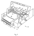
- Fig. 1 is one exemplary embodiment of an ink jet printing system, depicted with a cover opened to show a plurality of replaceable ink containers with which the off-axis supply adaptor of the present invention may be utilized.
- Fig. 2 is a simplified schematic representation of the exemplary inkjet printing system shown in Fig. 1.
- Fig. 3 is a greatly enlarged perspective view of a portion of a scanning carriage showing the replaceable ink containers positioned in a receiving station that provides fluid communication between the replaceable ink containers and one or more printheads.
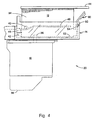
- Fig. 4 is a side plan view of a portion of the scanning carriage showing guiding and latching features associated with each of the replaceable ink container and the receiving station for securing the replaceable ink container, thereby allowing fluid communication with the printhead.
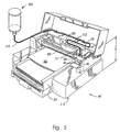
- Fig. 5 shows an exemplary embodiment of an ink jet printing system of system modified to accommodate the off-axis supply adaptor of the present invention.
- Fig. 6 is a simplified exploded view illustrating an embodiment of the off-axis supply adaptor of the present invention, showing the modified ink delivery path.
- Fig. 7 is a simplified schematic representation further illustrating the modified ink jet printing system of Fig. 6.
- Fig. 8 is a simplified exploded view illustrating an alternate embodiment of the supply adaptor of the present invention, in which a large free-ink supply is carriage-mounted.
- Fig. 1 is a perspective view of one exemplary embodiment of a printing system 10 shown with its cover open, that includes at least one replaceable ink container 12 installed in a receiving station 14. With the replaceable ink container 12 properly installed into the receiving portion 14, ink is provided from the replaceable ink container 12 to at least one inkjet printhead 16.
- the inkjet printhead 16 is responsive to activation signals from a printer portion 18 to deposit ink on print media. As ink is ejected from the printhead 16, the printhead 16 is replenished with ink from the ink container 12.
- the replaceable ink container 12, receiving station 14, and inkjet printhead 16 are each part of a scanning carriage that is moved relative to a print media 22 to accomplish printing.
- the printer portion 18 also includes a media tray for receiving the print media 22. As the print media 22 is stepped through a printing zone, the scanning carriage 20 moves the printhead 16 relative to the print media 22. The printer portion 18 selectively activates the printhead 16 to deposit ink on print media 22 to thereby accomplish printing.
- the scanning carriage 20 is moved through the print zone on a scanning mechanism which includes a slide rod 26 on which the scanning carriage 20 slides as the scanning carriage 20 moves through a scan axis.
- a positioning means (not shown) is used for precisely positioning the scanning carriage 20.
- a paper advance mechanism (not shown) is used to step the print media 22 through the print zone as the scanning carriage 20 is moved along the scan axis.
- Electrical signals are provided to the scanning carriage 20 for selectively activating the printhead 16 by means of an electrical link such as a ribbon cable 28.
- the fluidic interconnection allows a supply of ink within the replaceable ink container 12 to be fluidically coupled to the printhead 16 for providing a source of ink to the printhead 16.
- the electrical interconnection allows information to be passed between the replaceable ink container 12 and the printer portion 18.
- Information passed between the replaceable ink container 12 and the printer portion 18 can include, by way of example, information related to the compatibility of replaceable ink container 12 with printer portion 18 and operation status information such as the ink level information.
- New ink containers 12 are provided to the printer user with the fluid port sealed to prevent ink spillage during shipping and storage. It is critical that the fluid port be unsealed prior to installing a new ink container in the printer, since operating the printer without a reliable supply of ink can cause permanent damage of the printheads.
- the fluid interconnect label lock-out tab of the present invention ensures that a new ink container 12 is not installed into the receiving portion 14 with the fluid interconnect seal in place.
- Fig. 2 is a simplified schematic representation of the exemplary inkjet printing system 10 shown in Fig. 1.
- Fig. 2 is simplified to illustrate a single printhead 16 connected to a single ink container 12.
- the inkjet printing system 10 of the present invention includes the printer portion 18 and the ink container 12, which is configured to be received by the printer portion 18.
- the printer portion 18 includes the inkjet printhead 16 and a controller 29.
- an electrical and fluidic coupling is established between the ink container 12 and the printer portion 18.
- the fluidic coupling allows ink stored within the ink container 12 to be provided to the printhead 16.
- a fluid interconnect 36 engages the fluid port 37 of the ink container, establishing fluid flow.
- the fluid interconnect 36 may comprise a separate manifold component on the scanning carriage 20, as discussed below.
- the electrical coupling allows information to be passed between an electrical storage device 80 disposed on the ink container 12 and the printer portion 18.
- the exchange of information between the ink container 12 and the printer portion 18 is to ensure the operation of the printer portion 18 is compatible with the ink contained within the replaceable ink container 12 thereby achieving high print quality and reliable operation of the printing system 10.
- the controller 29 controls the transfer of information between the printer portion 18 and the replaceable ink container 12.
- the controller 29 controls the transfer of information between the printhead 16 and the controller 29 for activating the printhead to selectively deposit ink on print media, and controls the relative movement of the printhead 16 and print media.
- the controller 29 performs additional functions such as controlling the transfer of information between the printing system 10 and a host device such as a computer (not shown).
- the controller 29 may utilize parameters that are provided by the electrical storage device 80 to optimize the printer operation.
- the parameters for example, that can be stored in the electrical storage device 80 associated with the replaceable ink container 12 are following: a date code associated with the replaceable ink container 12, a date code of initial insertion of the ink container 12, system coefficients, ink type and ink color, ink container size, printer model number or identification number and container usage information, just to name a few.
- Fig. 3 is a perspective view of a portion of the scanning carriage 20 showing a pair of replaceable ink containers 12 properly installed in the receiving station 14.
- An inkjet printhead 16 is in fluid communication with the receiving station 14.
- the inkjet printing system 10 shown in Fig. 1 includes a tri-color ink container containing three separate ink colors (cyan, magenta, and yellow) and a second ink container containing black ink.
- the replaceable ink containers 12 can be partitioned differently to contain fewer than three ink colors or more than three ink colors if more are required. For example, in the case of high fidelity printing, frequently six or more colors are used.
- the scanning carriage portion 20 shown in Fig. 3 is shown fluidically coupled to a single printhead 16 for simplicity.
- four inkjet printheads 16 are each fluidically coupled to the receiving station 14.
- each of the four printheads are fluidically coupled to each of the four colored inks contained in the replaceable ink containers 12.
- Each of the replaceable ink containers 12 include a latch 30 for securing the replaceable ink container 12 to the receiving station 14.
- the receiving station 14 in the preferred embodiment includes a set of keys 32 that interact with corresponding keying features (not shown) on the replaceable ink container 12.
- the keying features on the replaceable ink container 12 interact with the keys 32 on the receiving station 14 to ensure that the replaceable ink container 12 is compatible with the receiving station 14.
- Fig. 4 is a side plan view of the scanning carriage portion 20 shown in Fig. 2.
- the scanning carriage portion 20 includes the ink container 12 shown properly installed into the receiving station 14, thereby establishing fluid communication between the replaceable ink container 12 and the printhead 16.
- the replaceable ink container 12 includes a reservoir portion 34 for containing one or more quantities of ink.
- the tri-color replaceable ink container 12 has three separate ink containment reservoirs, each containing ink of a different color.
- the black replaceable ink container 12 is a single ink reservoir 34 for containing black ink.
- the reservoir 34 has a capillary storage member (not shown) disposed therein.
- the capillary storage member is a porous member having sufficient capillarity to retain ink to prevent ink leakage from the reservoir 34 during insertion and removal of the ink container 12 from the printing system 10.
- the capillary force must be sufficiently great to prevent ink leakage from the ink reservoir 34 over a wide variety of environmental conditions such as temperature and pressure changes.
- the capillarity of the capillary member is sufficient to retain ink within the ink reservoir 34 for all orientations of the ink reservoir as well as a reasonable amount of shock and vibration the ink container may experience during normal handling.
- the preferred capillary storage member is a network of heat bonded polymer fibers, although any suitable capillary material may be used.
- the ink container 12 is fluidically coupled to the printhead 16 by way of fluid interconnect 36.
- ink is ejected from the ejection portion 38 producing a negative gauge pressure, sometimes referred to as backpressure, within the printhead 16.
- This negative gauge pressure within the printhead 16 is sufficient to overcome the capillary force resulting from the capillary member disposed within the ink reservoir 34.
- Ink is drawn by this backpressure from the replaceable ink container 12 to the printhead 16. In this manner, the printhead 16 is replenished with ink provided by the replaceable ink container 12.
- the fluid interconnect 36 of the exemplary embodiment is preferably an upstanding ink pipe that extends upwardly into the ink container 12 and downwardly to the inkjet printhead 16.
- the fluid interconnect 36 is shown greatly simplified in Fig. 4.
- the fluid interconnect 36 is a manifold that allows for offset in the positioning of the printheads 16 along the scan axis, thereby allowing the printhead 16 to be placed offset from the corresponding replaceable ink container 12.
- the fluid interconnect 36 extends into the reservoir 34 to compress the capillary member, thereby forming a region of increased capillarity adjacent the fluid interconnect 36. This region of increased capillarity tends to draw ink toward the fluid interconnect 36, thereby allowing ink to flow through the fluid interconnect 36 to the printhead 16.
- the replaceable ink container 12 further includes a guide feature 40, an engagement feature 42, a handle 44 and a latch feature 30 that allow the ink container 12 to be inserted into the receiving station 14 to achieve reliable fluid interconnection with the printhead 16 as well as form reliable electrical interconnection between the replaceable ink container 12 and the scanning carriage 20.
- the receiving station 14 includes a guide rail 46, an engagement feature 48 and a latch engagement feature 50.
- the guide rail 46 cooperates with the guide rail engagement feature 40 and the replaceable ink container 12 to guide the ink container 12 into the receiving station 14.
- the engagement feature 42 associated with the replaceable ink container engages the engagement feature 48 associated with the receiving station 14, securing a front end or a leading end of the replaceable ink container 12 to the receiving station 14.
- the ink container 12 is then pressed downward to compress a spring biasing member 52 associated with the receiving station 14 until a latch engagement feature 50 associated with the receiving station 14 engages a hook feature 54 associated with the latch member 30 to secure a back end or trailing end of the ink container 12 to the receiving station 14. It is the cooperation of the features on the ink container 12 with the features associated with the receiving station 14 that allow proper insertion and functional interfacing between the replaceable ink container 12 and the receiving station 14.
- Fig. 5 depicts an exemplary embodiment of an ink jet printing system 10'modified to accommodate the off-axis supply adaptor of the present invention.
- an off-axis Ink supply 102 is plumbed via a flexible tube 110 to the fluidic interconnect between the scanning print head and the original on axis ink supply.
- a relief loop 112 in the tube allows the printer scanning carriage portion 20 to freely scan across the media 22.
- the remote supply 102 may be attached to the side of the printer housing at the appropriate height relative to the print head to provide appropriate system backpressure and fluid flow function, or may be otherwise mounted in any convenient manner.
- the supply pressure may be controlled in some other manner to allow convenient mounting of the remote supply, such as by pressurizing the supply, as is well-known in the art (not shown).
- the supply 102 is preferably made of a clear material to provide visual ink level feedback to the operator, or the supply could incorporate any of a number of common fluid level indicators known in the art.
- the flexible tube 110 (excepting the relief loop) may be affixed to the printer in any convenient manner, such as adhesives or plastic ties.
- Fig. 5 illustrates a printer system modified to accept an off-axis supply of one ink color, such as black; the concept of the present invention may be extended to multiple off-axis supplies.
- Fig. 6 is a simplified exploded view of the off-axis supply adaptor of the present invention, showing the modified ink delivery path.
- the off-axis ink supply 102 of the exemplary embodiment comprises a clear plastic container 104 with a removable top lid 106 to allow for easy refilling, and is connected to the flexible tube 1 IO by a cap 108.
- modified ink supply 12 comprises a standard ink supply with both the top cover and the internal capillary material removed, thus providing access to the fluid port 37 of the ink container.
- the electrical storage device 80 (not shown in Fig. 6) of the modified ink supply is discussed with respect to Fig. 7, below.
- the flexible tube 1 IO engages the fluid interconnect 36 of the printer, which extends through the fluid port 37 when the modified ink supply is installed in the printer.
- the off-axis ink supply 102 is thus in fluid communication with printhead 16.
- the flexible tube is first "primed" with ink prior to attachment to the fluid interconnect 36 to avoid ink starvation of the printhead.
- Fig. 7 is a simplified schematic representation further illustrating the modified ink jet printing system 10 of Fig. 6, with a single printhead 16 connected to a single ink container 12.
- the printer portion 18 includes the inkjet printhead 16 and a controller 29.
- Modified ink container 12' provides electrical and fluidic coupling with the printer portion 18 as discussed with respect to Fig. 2, above.
- the electrical coupling allows information to be passed between the electrical storage device 80 on the modified ink container 12'and the printer portion 18.
- the exchange of information between the modified ink container 12'and the printer portion 18 provides compatibility with the printer by implementing or emulating those functions discussed with respect to the unmodified printer system of Fig. 2, above.
- the electrical storage device may also be programmed to optimize printing with the off-axis adaptor, with data indicating any special characteristics of the off-axis supply, such as the ink capacity of the supply.
- Fig. 8 is a simplified exploded view illustrating an alternate embodiment of the supply adaptor of the present invention, in which a large free-ink supply is carriage-mounted.
- the carriage-mounted ink supply 202 of the alternate embodiment comprises a clear plastic container 204 with a removable top lid 206 to allow for easy refilling.
- a short resilient member 210 which may be a piece of flexible tubing, allows the supply to engage the fluid interconnect 36 of the printer which extends through the fluid port 37 when the modified ink supply is installed in the printer.
- the modified ink supply 12' comprises a standard ink supply with both the top cover and the internal capillary material removed. In use, the carriage-mounted supply is installed in the printer and then filled with ink. The operator can visually monitor the ink level in the supply, and refill it when necessary.
- the present invention may be extended to multiple off-axis supplies, such as supplies for each primary color in a color printing system.
- the present invention provides the additional benefit of lower ink wastage, since printer users who tend to predominantly print specific colors can replenished the colors separately, as opposed to the replacing a common "ganged" on-axis color ink supply.
- the modified printing system of the present invention provides an option to printer users who want to purchase a lower price on-axis ink supply printer and maintain the flexibility to use it in high usage applications with a convenient intervention rate and lower overall cost per page operating costs.
- This present invention also provides visual feedback to the user about ink level therefore protecting against premature print head degradation (from air ingestion).
- the present invention is applicable to other printer systems having on-axis ink supplies separately replaceable from the printheads.
Landscapes
- Ink Jet (AREA)
Abstract
Supply adaptors are disclosed for modifying existing low cost "on-axis" ink jet
printer systems (10) to accommodate low intervention rate "free ink" ink
supplies (102, 202). Embodiments are disclosed which enable reduced
intervention rates and visual ink level indication by providing a large ink
container (102, 202), flexible interconnect tubing (110, 210), and a modified
ink supply container (12') which mounts to the printer carriage.
Description
- The present invention relates to an adaptor for providing ink to a printing system. More specifically, exemplary embodiments of the present invention relate to a "free ink" reservoir adaptor for an ink jet printer having on-axis ink supplies.
- Inkjet printers typically use a printhead mounted on a carriage that is moved relative to a print media, such as paper. As the printhead is moved relative to the print media, a control system activates the printhead to deposit or eject ink droplets onto the print media to form images and text. Ink is provided to the printhead by a supply of ink that is either integral with the printhead, as in the case of a disposable print cartridge, or by a supply of ink that is replaceable separate from the printhead. With separately replaceable ink supplies, the ink supply is replaced when exhausted, and the printhead is then replaced at the end of the printhead useful life.
- When the ink supply is replaceable separate from the printhead, the supply may be either located on the carriage with the printhead or located remotely from the printhead ("off axis"). Locating the supply on the carriage with the printhead is generally a less expensive approach, although the quantity of ink provided with each replaceable supply is limited by the considerations of the total mass that must be moved on the carriage, and the spatial volume swept by the carriage.
- Locating the ink supplies on the carriage provides a cost effective printer configuration, as the cost of the ink delivery system is thereby reduced. Since the capacity of on-axis supplies are necessarily limited, however, the configuration may not be suitable for users having high-volume printing requirements and therefore needing a printer that will print for long periods unattended. Off axis low intervention rate printers exist, but generally at higher cost, due to the more expensive ink delivery system.
- There is therefore a need for devices which allow the use of cost effective on-axis ink jet printers in a high-volume low intervention rate environment.
- Embodiments of the present invention comprise apparatus and methods for modifying existing low cost "on-axis" ink jet printer systems to accommodate low intervention rate "free ink" ink supplies. Embodiments are disclosed which enable reduced intervention rates and visual ink level indication by providing an large ink container, flexible interconnect tubing, and a modified ink supply container which mounts to the printer carriage.
- Other aspects and advantages of the present invention will become apparent from the following detailed description, taken in conjunction with the accompanying drawings, illustrating by way of example the principles of the invention.
- Fig. 1 is one exemplary embodiment of an ink jet printing system, depicted with a cover opened to show a plurality of replaceable ink containers with which the off-axis supply adaptor of the present invention may be utilized.
- Fig. 2 is a simplified schematic representation of the exemplary inkjet printing system shown in Fig. 1.
- Fig. 3 is a greatly enlarged perspective view of a portion of a scanning carriage showing the replaceable ink containers positioned in a receiving station that provides fluid communication between the replaceable ink containers and one or more printheads.
- Fig. 4 is a side plan view of a portion of the scanning carriage showing guiding and latching features associated with each of the replaceable ink container and the receiving station for securing the replaceable ink container, thereby allowing fluid communication with the printhead.
- Fig. 5 shows an exemplary embodiment of an ink jet printing system of system modified to accommodate the off-axis supply adaptor of the present invention.
- Fig. 6 is a simplified exploded view illustrating an embodiment of the off-axis supply adaptor of the present invention, showing the modified ink delivery path.
- Fig. 7 is a simplified schematic representation further illustrating the modified ink jet printing system of Fig. 6.
- Fig. 8 is a simplified exploded view illustrating an alternate embodiment of the supply adaptor of the present invention, in which a large free-ink supply is carriage-mounted.
- Fig. 1 is a perspective view of one exemplary embodiment of a
printing system 10 shown with its cover open, that includes at least onereplaceable ink container 12 installed in areceiving station 14. With thereplaceable ink container 12 properly installed into thereceiving portion 14, ink is provided from thereplaceable ink container 12 to at least oneinkjet printhead 16. Theinkjet printhead 16 is responsive to activation signals from aprinter portion 18 to deposit ink on print media. As ink is ejected from theprinthead 16, theprinthead 16 is replenished with ink from theink container 12. In one preferred embodiment, thereplaceable ink container 12, receivingstation 14, andinkjet printhead 16 are each part of a scanning carriage that is moved relative to aprint media 22 to accomplish printing. Theprinter portion 18 also includes a media tray for receiving theprint media 22. As theprint media 22 is stepped through a printing zone, the scanningcarriage 20 moves theprinthead 16 relative to theprint media 22. Theprinter portion 18 selectively activates theprinthead 16 to deposit ink onprint media 22 to thereby accomplish printing. - The
scanning carriage 20 is moved through the print zone on a scanning mechanism which includes aslide rod 26 on which the scanningcarriage 20 slides as thescanning carriage 20 moves through a scan axis. A positioning means (not shown) is used for precisely positioning thescanning carriage 20. In addition, a paper advance mechanism (not shown) is used to step theprint media 22 through the print zone as thescanning carriage 20 is moved along the scan axis. Electrical signals are provided to thescanning carriage 20 for selectively activating theprinthead 16 by means of an electrical link such as aribbon cable 28. - It is essential for the proper operation of the printing system that, when an
ink container 12 is replaced, both proper fluidic and electrical connection be established between theink container 12 and theprinter portion 18. The fluidic interconnection allows a supply of ink within thereplaceable ink container 12 to be fluidically coupled to theprinthead 16 for providing a source of ink to theprinthead 16. The electrical interconnection allows information to be passed between thereplaceable ink container 12 and theprinter portion 18. Information passed between thereplaceable ink container 12 and theprinter portion 18 can include, by way of example, information related to the compatibility ofreplaceable ink container 12 withprinter portion 18 and operation status information such as the ink level information. -
New ink containers 12 are provided to the printer user with the fluid port sealed to prevent ink spillage during shipping and storage. It is critical that the fluid port be unsealed prior to installing a new ink container in the printer, since operating the printer without a reliable supply of ink can cause permanent damage of the printheads. The fluid interconnect label lock-out tab of the present invention, as will be discussed with respect to Figs. 5 through 10, ensures that anew ink container 12 is not installed into thereceiving portion 14 with the fluid interconnect seal in place. - Fig. 2 is a simplified schematic representation of the exemplary
inkjet printing system 10 shown in Fig. 1. Fig. 2 is simplified to illustrate asingle printhead 16 connected to asingle ink container 12. Theinkjet printing system 10 of the present invention includes theprinter portion 18 and theink container 12, which is configured to be received by theprinter portion 18. Theprinter portion 18 includes theinkjet printhead 16 and acontroller 29. With theink container 12 properly inserted into theprinter portion 18, an electrical and fluidic coupling is established between theink container 12 and theprinter portion 18. The fluidic coupling allows ink stored within theink container 12 to be provided to theprinthead 16. Upon installation of the ink container, afluid interconnect 36 engages thefluid port 37 of the ink container, establishing fluid flow. Thefluid interconnect 36 may comprise a separate manifold component on thescanning carriage 20, as discussed below. The electrical coupling allows information to be passed between anelectrical storage device 80 disposed on theink container 12 and theprinter portion 18. The exchange of information between theink container 12 and theprinter portion 18 is to ensure the operation of theprinter portion 18 is compatible with the ink contained within thereplaceable ink container 12 thereby achieving high print quality and reliable operation of theprinting system 10. - The
controller 29, among other functions, controls the transfer of information between theprinter portion 18 and thereplaceable ink container 12. In addition, thecontroller 29 controls the transfer of information between theprinthead 16 and thecontroller 29 for activating the printhead to selectively deposit ink on print media, and controls the relative movement of theprinthead 16 and print media. Thecontroller 29 performs additional functions such as controlling the transfer of information between theprinting system 10 and a host device such as a computer (not shown). - In order to ensure the
printing system 10 provides high quality images on print media, thecontroller 29 may utilize parameters that are provided by theelectrical storage device 80 to optimize the printer operation. Among the parameters, for example, that can be stored in theelectrical storage device 80 associated with thereplaceable ink container 12 are following: a date code associated with thereplaceable ink container 12, a date code of initial insertion of theink container 12, system coefficients, ink type and ink color, ink container size, printer model number or identification number and container usage information, just to name a few. - Fig. 3 is a perspective view of a portion of the
scanning carriage 20 showing a pair ofreplaceable ink containers 12 properly installed in thereceiving station 14. Aninkjet printhead 16 is in fluid communication with thereceiving station 14. In the preferred embodiment, theinkjet printing system 10 shown in Fig. 1 includes a tri-color ink container containing three separate ink colors (cyan, magenta, and yellow) and a second ink container containing black ink. Thereplaceable ink containers 12 can be partitioned differently to contain fewer than three ink colors or more than three ink colors if more are required. For example, in the case of high fidelity printing, frequently six or more colors are used. - The
scanning carriage portion 20 shown in Fig. 3 is shown fluidically coupled to asingle printhead 16 for simplicity. In the exemplary embodiment, fourinkjet printheads 16 are each fluidically coupled to the receivingstation 14. In this embodiment, each of the four printheads are fluidically coupled to each of the four colored inks contained in thereplaceable ink containers 12. - Each of the
replaceable ink containers 12 include alatch 30 for securing thereplaceable ink container 12 to the receivingstation 14. The receivingstation 14 in the preferred embodiment includes a set ofkeys 32 that interact with corresponding keying features (not shown) on thereplaceable ink container 12. The keying features on thereplaceable ink container 12 interact with thekeys 32 on the receivingstation 14 to ensure that thereplaceable ink container 12 is compatible with the receivingstation 14. - Fig. 4 is a side plan view of the
scanning carriage portion 20 shown in Fig. 2. Thescanning carriage portion 20 includes theink container 12 shown properly installed into the receivingstation 14, thereby establishing fluid communication between thereplaceable ink container 12 and theprinthead 16. Thereplaceable ink container 12 includes areservoir portion 34 for containing one or more quantities of ink. In the exemplary embodiment, the tri-colorreplaceable ink container 12 has three separate ink containment reservoirs, each containing ink of a different color. The blackreplaceable ink container 12 is asingle ink reservoir 34 for containing black ink. In the exemplary embodiment, thereservoir 34 has a capillary storage member (not shown) disposed therein. The capillary storage member is a porous member having sufficient capillarity to retain ink to prevent ink leakage from thereservoir 34 during insertion and removal of theink container 12 from theprinting system 10. - This capillary force must be sufficiently great to prevent ink leakage from the
ink reservoir 34 over a wide variety of environmental conditions such as temperature and pressure changes. In addition, the capillarity of the capillary member is sufficient to retain ink within theink reservoir 34 for all orientations of the ink reservoir as well as a reasonable amount of shock and vibration the ink container may experience during normal handling. The preferred capillary storage member is a network of heat bonded polymer fibers, although any suitable capillary material may be used. - Once the
ink container 12 is properly installed into the receivingstation 14, theink container 12 is fluidically coupled to theprinthead 16 by way offluid interconnect 36. Upon activation of theprinthead 16, ink is ejected from theejection portion 38 producing a negative gauge pressure, sometimes referred to as backpressure, within theprinthead 16. This negative gauge pressure within theprinthead 16 is sufficient to overcome the capillary force resulting from the capillary member disposed within theink reservoir 34. Ink is drawn by this backpressure from thereplaceable ink container 12 to theprinthead 16. In this manner, theprinthead 16 is replenished with ink provided by thereplaceable ink container 12. - The
fluid interconnect 36 of the exemplary embodiment is preferably an upstanding ink pipe that extends upwardly into theink container 12 and downwardly to theinkjet printhead 16. Thefluid interconnect 36 is shown greatly simplified in Fig. 4. In the exemplary embodiment, thefluid interconnect 36 is a manifold that allows for offset in the positioning of theprintheads 16 along the scan axis, thereby allowing theprinthead 16 to be placed offset from the correspondingreplaceable ink container 12. In the preferred embodiment, thefluid interconnect 36 extends into thereservoir 34 to compress the capillary member, thereby forming a region of increased capillarity adjacent thefluid interconnect 36. This region of increased capillarity tends to draw ink toward thefluid interconnect 36, thereby allowing ink to flow through thefluid interconnect 36 to theprinthead 16. - The
replaceable ink container 12 further includes aguide feature 40, anengagement feature 42, ahandle 44 and alatch feature 30 that allow theink container 12 to be inserted into the receivingstation 14 to achieve reliable fluid interconnection with theprinthead 16 as well as form reliable electrical interconnection between thereplaceable ink container 12 and thescanning carriage 20. - The receiving
station 14 includes aguide rail 46, anengagement feature 48 and alatch engagement feature 50. Theguide rail 46 cooperates with the guiderail engagement feature 40 and thereplaceable ink container 12 to guide theink container 12 into the receivingstation 14. Once thereplaceable ink container 12 is fully inserted into the receivingstation 14, theengagement feature 42 associated with the replaceable ink container engages theengagement feature 48 associated with the receivingstation 14, securing a front end or a leading end of thereplaceable ink container 12 to the receivingstation 14. Theink container 12 is then pressed downward to compress aspring biasing member 52 associated with the receivingstation 14 until alatch engagement feature 50 associated with the receivingstation 14 engages ahook feature 54 associated with thelatch member 30 to secure a back end or trailing end of theink container 12 to the receivingstation 14. It is the cooperation of the features on theink container 12 with the features associated with the receivingstation 14 that allow proper insertion and functional interfacing between thereplaceable ink container 12 and the receivingstation 14. - Fig. 5 depicts an exemplary embodiment of an ink jet printing system 10'modified to accommodate the off-axis supply adaptor of the present invention. As shown in Fig. 5, an off-
axis Ink supply 102 is plumbed via aflexible tube 110 to the fluidic interconnect between the scanning print head and the original on axis ink supply. Arelief loop 112 in the tube allows the printerscanning carriage portion 20 to freely scan across themedia 22. Theremote supply 102 may be attached to the side of the printer housing at the appropriate height relative to the print head to provide appropriate system backpressure and fluid flow function, or may be otherwise mounted in any convenient manner. Furthermore, the supply pressure may be controlled in some other manner to allow convenient mounting of the remote supply, such as by pressurizing the supply, as is well-known in the art (not shown). Thesupply 102 is preferably made of a clear material to provide visual ink level feedback to the operator, or the supply could incorporate any of a number of common fluid level indicators known in the art. The flexible tube 110 (excepting the relief loop) may be affixed to the printer in any convenient manner, such as adhesives or plastic ties. - For printing systems that require electronic communication between the printer and the electrical storage device 80 (not shown in Fig. 5) on the on-axis ink supply, either an old (modified) ink supply 12', as discussed below, or an electronic device emulating the function of an electrical storage device can be used to preserve the required electrical interface. While Fig. 5 illustrates a printer system modified to accept an off-axis supply of one ink color, such as black; the concept of the present invention may be extended to multiple off-axis supplies.
- Fig. 6 is a simplified exploded view of the off-axis supply adaptor of the present invention, showing the modified ink delivery path. The off-
axis ink supply 102 of the exemplary embodiment comprises a clearplastic container 104 with a removabletop lid 106 to allow for easy refilling, and is connected to theflexible tube 1 IO by acap 108. - As shown in Fig. 6, modified ink supply 12'comprises a standard ink supply with both the top cover and the internal capillary material removed, thus providing access to the
fluid port 37 of the ink container. The electrical storage device 80 (not shown in Fig. 6) of the modified ink supply is discussed with respect to Fig. 7, below. In the exemplary embodiment, theflexible tube 1 IO engages thefluid interconnect 36 of the printer, which extends through thefluid port 37 when the modified ink supply is installed in the printer. The off-axis ink supply 102 is thus in fluid communication withprinthead 16. In the exemplary embodiment, the flexible tube is first "primed" with ink prior to attachment to thefluid interconnect 36 to avoid ink starvation of the printhead. - Fig. 7 is a simplified schematic representation further illustrating the modified ink
jet printing system 10 of Fig. 6, with asingle printhead 16 connected to asingle ink container 12. Theprinter portion 18 includes theinkjet printhead 16 and acontroller 29. Modified ink container 12'provides electrical and fluidic coupling with theprinter portion 18 as discussed with respect to Fig. 2, above. The electrical coupling allows information to be passed between theelectrical storage device 80 on the modified ink container 12'and theprinter portion 18. The exchange of information between the modified ink container 12'and theprinter portion 18 provides compatibility with the printer by implementing or emulating those functions discussed with respect to the unmodified printer system of Fig. 2, above. The electrical storage device may also be programmed to optimize printing with the off-axis adaptor, with data indicating any special characteristics of the off-axis supply, such as the ink capacity of the supply. - Fig. 8 is a simplified exploded view illustrating an alternate embodiment of the supply adaptor of the present invention, in which a large free-ink supply is carriage-mounted. The carriage-mounted ink supply 202 of the alternate embodiment comprises a clear
plastic container 204 with a removabletop lid 206 to allow for easy refilling. A shortresilient member 210, which may be a piece of flexible tubing, allows the supply to engage thefluid interconnect 36 of the printer which extends through thefluid port 37 when the modified ink supply is installed in the printer. As in the above-described exemplary embodiment, the modified ink supply 12'comprises a standard ink supply with both the top cover and the internal capillary material removed. In use, the carriage-mounted supply is installed in the printer and then filled with ink. The operator can visually monitor the ink level in the supply, and refill it when necessary. - While described above with respect to a single off-axis ink supply, the present invention may be extended to multiple off-axis supplies, such as supplies for each primary color in a color printing system. In a color printing system, the present invention provides the additional benefit of lower ink wastage, since printer users who tend to predominantly print specific colors can replenished the colors separately, as opposed to the replacing a common "ganged" on-axis color ink supply.
- The modified printing system of the present invention provides an option to printer users who want to purchase a lower price on-axis ink supply printer and maintain the flexibility to use it in high usage applications with a convenient intervention rate and lower overall cost per page operating costs. This present invention also provides visual feedback to the user about ink level therefore protecting against premature print head degradation (from air ingestion).
- Although described with respect to a particular exemplary embodiment, the present invention is applicable to other printer systems having on-axis ink supplies separately replaceable from the printheads.
- The above is a detailed description of particular embodiments of the invention. It is recognized that departures from the disclosed embodiments may be within the scope of this invention and that obvious modifications will occur to a person skilled in the art. It is the intent of the applicant that the invention include alternative implementations known in the art that perform the same functions as those disclosed. This specification should not be construed to unduly narrow the full scope of protection to which the invention is entitled.
Claims (10)
- An ink delivery system for providing ink to the scanning carriage (20) of an ink jet printer, the printer configured to receive carriage-mounted ink supplies (12) separately replaceable from the printheads (16), comprising:an ink container (102, 202);an adaptor member (12') configured to be received by a printer carriage in place of a carriage mounted ink supply; andflexible tubing (110, 210) fluidically coupling the ink container with the adaptor member.
- The ink delivery system for providing ink to the scanning carriage of an ink jet printer of Claim 1, wherein the ink container (102, 202) is formed from a plastic bottle.
- The ink delivery system for providing ink to the scanning carriage of an ink jet printer of Claim 1 or Claim 2, wherein the ink container (102, 202) further comprises an ink level indicator.
- The ink delivery system for providing ink to the scanning carriage of an ink jet printer of Claim 3, wherein the ink supply (102, 202) has an outer wall and an inner ink-containing chamber, and wherein the ink level indicator comprises a substantially clear portion of the outer wall permitting visual inspection of ink within the ink-containing chamber.
- The ink delivery system for providing ink to the scanning carriage of an ink jet printer of Claim 1 or Claim 2, wherein the ink container (102, 202) further comprises a top lid (106, 206), the top lid replaceably removable for replenishing ink within the ink container.
- The ink delivery system for providing ink to the scanning carriage of an ink jet printer of Claim 1 or Claim 2, wherein the ink container (102) further comprises a lower cap (108), the lower cap retaining the flexible tubing to the in container.
- The ink delivery system for providing ink to the scanning carriage of an ink jet printer of Claim 1 or Claim 2, wherein the adaptor member (12') has a fluid port (37) configured to duplicate the fluid port on a carriage-mounted ink container, and wherein the flexible tubing (110, 210) connects to the fluid port.
- The ink delivery system for providing ink to the scanning carriage of an ink jet printer of Claim 1 or Claim 2, wherein the adaptor member (12') further comprises an electrical storage device (80) and electrical contacts configured to duplicate the electrical contacts on a carriage-mounted ink container.
- The ink delivery system for providing ink to the scanning carriage of an ink jet printer of Claim 8, wherein the electrical storage device (80) is preprogrammed with information to emulate the information in a carriage-mounted ink container electrical storage device.
- The ink delivery system for providing ink to the scanning carriage of an ink jet printer of Claim 1 or Claim 2, wherein the flexible tubing (110) forms a relief loop allowing normal scanning of the printer carriage.
Applications Claiming Priority (2)
| Application Number | Priority Date | Filing Date | Title |
|---|---|---|---|
| US53372 | 2001-10-24 | ||
| US10/053,372 US20030076391A1 (en) | 2001-10-24 | 2001-10-24 | Supply adaptor for an on-axis printer |
Publications (1)
| Publication Number | Publication Date |
|---|---|
| EP1306220A1 true EP1306220A1 (en) | 2003-05-02 |
Family
ID=21983761
Family Applications (1)
| Application Number | Title | Priority Date | Filing Date |
|---|---|---|---|
| EP02256888A Withdrawn EP1306220A1 (en) | 2001-10-24 | 2002-10-03 | Supply adaptor for an on-axis printer |
Country Status (3)
| Country | Link |
|---|---|
| US (1) | US20030076391A1 (en) |
| EP (1) | EP1306220A1 (en) |
| JP (1) | JP2003127427A (en) |
Cited By (4)
| Publication number | Priority date | Publication date | Assignee | Title |
|---|---|---|---|---|
| EP2316652A1 (en) * | 2009-10-29 | 2011-05-04 | Fieldcenter Inc. | Compatible ink cartridge for large format ink jet printers |
| CN101683789B (en) * | 2005-02-02 | 2013-08-14 | 精工爱普生株式会社 | Attachment, liquid container and liquid supply device |
| US8915572B2 (en) | 2012-02-23 | 2014-12-23 | Dip-Tech Ltd. | Printhead adapter for pigmented ink |
| CN104669770A (en) * | 2015-02-05 | 2015-06-03 | 力嘉包装(深圳)有限公司 | Quantitative ink supply method and quantitative ink supply system for offset presses |
Families Citing this family (38)
| Publication number | Priority date | Publication date | Assignee | Title |
|---|---|---|---|---|
| US7441865B2 (en) * | 2004-01-21 | 2008-10-28 | Silverbrook Research Pty Ltd | Printhead chip having longitudinal ink supply channels |
| US7731327B2 (en) * | 2004-01-21 | 2010-06-08 | Silverbrook Research Pty Ltd | Desktop printer with cartridge incorporating printhead integrated circuit |
| US7448734B2 (en) * | 2004-01-21 | 2008-11-11 | Silverbrook Research Pty Ltd | Inkjet printer cartridge with pagewidth printhead |
| US7121655B2 (en) * | 2004-01-21 | 2006-10-17 | Silverbrook Research Pty Ltd | Inkjet printer cartridge refill dispenser |
| US7645025B2 (en) * | 2004-01-21 | 2010-01-12 | Silverbrook Research Pty Ltd | Inkjet printer cartridge with two printhead integrated circuits |
| US7469989B2 (en) * | 2004-01-21 | 2008-12-30 | Silverbrook Research Pty Ltd | Printhead chip having longitudinal ink supply channels interrupted by transverse bridges |
| US20050157112A1 (en) | 2004-01-21 | 2005-07-21 | Silverbrook Research Pty Ltd | Inkjet printer cradle with shaped recess for receiving a printer cartridge |
| US7374355B2 (en) * | 2004-01-21 | 2008-05-20 | Silverbrook Research Pty Ltd | Inkjet printer cradle for receiving a pagewidth printhead cartridge |
| US7364263B2 (en) * | 2004-01-21 | 2008-04-29 | Silverbrook Research Pty Ltd | Removable inkjet printer cartridge |
| US7303255B2 (en) * | 2004-01-21 | 2007-12-04 | Silverbrook Research Pty Ltd | Inkjet printer cartridge with a compressed air port |
| US7097291B2 (en) * | 2004-01-21 | 2006-08-29 | Silverbrook Research Pty Ltd | Inkjet printer cartridge with ink refill port having multiple ink couplings |
| US7425050B2 (en) * | 2004-01-21 | 2008-09-16 | Silverbrook Research Pty Ltd | Method for facilitating maintenance of an inkjet printer having a pagewidth printhead |
| US7328985B2 (en) * | 2004-01-21 | 2008-02-12 | Silverbrook Research Pty Ltd | Inkjet printer cartridge refill dispenser with security mechanism |
| US7461928B2 (en) * | 2005-01-26 | 2008-12-09 | Hewlett-Packard Development Company, L.P. | Fluid-delivery mechanism for fluid-ejection device |
| JP4561395B2 (en) * | 2005-02-18 | 2010-10-13 | セイコーエプソン株式会社 | Attachment and liquid supply device |
| US9889672B2 (en) | 2005-02-02 | 2018-02-13 | Seiko Epson Corporation | Attachment, liquid container, and liquid supply apparatus |
| JP5250275B2 (en) * | 2008-02-06 | 2013-07-31 | 株式会社セイコーアイ・インフォテック | Ink supply system for ink jet printer, ink supply method for ink jet printer, and ink jet printer |
| BRPI0923982A2 (en) | 2009-03-09 | 2016-01-19 | Hewlett Packard Development Co | ink supply container, ink supply set, and printhead assembly |
| CN106313903A (en) * | 2009-03-09 | 2017-01-11 | 惠普开发有限公司 | Ink supply container |
| JP2009262570A (en) * | 2009-07-09 | 2009-11-12 | Silverbrook Research Pty Ltd | Inkjet printer cartridge controlled over refilling |
| US8371682B1 (en) * | 2010-01-14 | 2013-02-12 | Americo Del Raso | Ink replenishing system for ink jet printers |
| JP4973764B2 (en) * | 2010-06-18 | 2012-07-11 | セイコーエプソン株式会社 | Liquid supply device |
| JP5884307B2 (en) * | 2011-06-15 | 2016-03-15 | セイコーエプソン株式会社 | Liquid container, liquid container complex, and liquid supply system |
| JP2013121658A (en) * | 2011-12-09 | 2013-06-20 | Seiko Epson Corp | Recording apparatus |
| JP5834951B2 (en) | 2012-01-25 | 2015-12-24 | セイコーエプソン株式会社 | Liquid container and liquid consumption device |
| JP6161869B2 (en) * | 2012-03-05 | 2017-07-12 | セイコーエプソン株式会社 | Liquid ejector |
| JP2013202789A (en) * | 2012-03-27 | 2013-10-07 | Seiko Epson Corp | Recording device |
| RU2014147004A (en) | 2012-04-23 | 2016-06-10 | Сейко Эпсон Корпорейшн | PAINT COMPOSITION FOR INKJET PRINTING, SUBMITTING A PAINT SYSTEM AND INK PRINTING DEVICE |
| US9278563B2 (en) * | 2012-08-10 | 2016-03-08 | Seiko Epson Corporation | Liquid ejecting apparatus |
| JP5958176B2 (en) * | 2012-08-22 | 2016-07-27 | セイコーエプソン株式会社 | Recording device |
| US9421781B2 (en) * | 2012-10-15 | 2016-08-23 | Seiko Epson Corporation | Recording apparatus |
| US9481180B2 (en) * | 2013-03-01 | 2016-11-01 | Seiko Epson Corporation | Liquid container, liquid container unit, liquid ejecting system, and liquid ejecting apparatus |
| CN108349261B (en) | 2016-01-27 | 2021-04-13 | 惠普发展公司,有限责任合伙企业 | Fluid Supply Components |
| JP6439721B2 (en) * | 2016-03-07 | 2018-12-19 | セイコーエプソン株式会社 | Liquid ejector |
| JP6439720B2 (en) * | 2016-03-07 | 2018-12-19 | セイコーエプソン株式会社 | Liquid ejector |
| JP6146517B2 (en) * | 2016-06-29 | 2017-06-14 | セイコーエプソン株式会社 | Recording device |
| JP2019188711A (en) * | 2018-04-26 | 2019-10-31 | セイコーエプソン株式会社 | Liquid supply body, liquid supply system, and manufacturing method for liquid supply body |
| JP7651980B2 (en) * | 2021-06-28 | 2025-03-27 | セイコーエプソン株式会社 | Cartridge and printing system |
Citations (5)
| Publication number | Priority date | Publication date | Assignee | Title |
|---|---|---|---|---|
| EP0778143A1 (en) * | 1995-12-04 | 1997-06-11 | Hewlett-Packard Company | Ink cartridge adapters |
| US5764260A (en) * | 1996-03-14 | 1998-06-09 | Jetfill, Inc. | Reusable inkjet cartridge adaptor |
| US5949461A (en) * | 1994-02-18 | 1999-09-07 | Nu-Kote Imaging International, Inc. | Ink refill bottle |
| EP0940260A1 (en) * | 1998-03-04 | 1999-09-08 | Hewlett-Packard Company | Ink delivery system adapter |
| WO2001019615A1 (en) * | 1999-09-13 | 2001-03-22 | Fullmark Private Limited | Method and apparatus for refilling an ink cartridge with a printhead mounted on it |
-
2001
- 2001-10-24 US US10/053,372 patent/US20030076391A1/en not_active Abandoned
-
2002
- 2002-10-03 EP EP02256888A patent/EP1306220A1/en not_active Withdrawn
- 2002-10-22 JP JP2002307099A patent/JP2003127427A/en active Pending
Patent Citations (5)
| Publication number | Priority date | Publication date | Assignee | Title |
|---|---|---|---|---|
| US5949461A (en) * | 1994-02-18 | 1999-09-07 | Nu-Kote Imaging International, Inc. | Ink refill bottle |
| EP0778143A1 (en) * | 1995-12-04 | 1997-06-11 | Hewlett-Packard Company | Ink cartridge adapters |
| US5764260A (en) * | 1996-03-14 | 1998-06-09 | Jetfill, Inc. | Reusable inkjet cartridge adaptor |
| EP0940260A1 (en) * | 1998-03-04 | 1999-09-08 | Hewlett-Packard Company | Ink delivery system adapter |
| WO2001019615A1 (en) * | 1999-09-13 | 2001-03-22 | Fullmark Private Limited | Method and apparatus for refilling an ink cartridge with a printhead mounted on it |
Cited By (7)
| Publication number | Priority date | Publication date | Assignee | Title |
|---|---|---|---|---|
| CN101683789B (en) * | 2005-02-02 | 2013-08-14 | 精工爱普生株式会社 | Attachment, liquid container and liquid supply device |
| CN102092198B (en) * | 2005-02-02 | 2013-08-28 | 精工爱普生株式会社 | Attachment, liquid container, and liquid supply apparatus |
| CN102092197B (en) * | 2005-02-02 | 2013-08-28 | 精工爱普生株式会社 | Attachment, liquid container, and liquid supply apparatus |
| CN102092195B (en) * | 2005-02-02 | 2013-09-04 | 精工爱普生株式会社 | Additional devices and liquid supply devices |
| EP2316652A1 (en) * | 2009-10-29 | 2011-05-04 | Fieldcenter Inc. | Compatible ink cartridge for large format ink jet printers |
| US8915572B2 (en) | 2012-02-23 | 2014-12-23 | Dip-Tech Ltd. | Printhead adapter for pigmented ink |
| CN104669770A (en) * | 2015-02-05 | 2015-06-03 | 力嘉包装(深圳)有限公司 | Quantitative ink supply method and quantitative ink supply system for offset presses |
Also Published As
| Publication number | Publication date |
|---|---|
| US20030076391A1 (en) | 2003-04-24 |
| JP2003127427A (en) | 2003-05-08 |
Similar Documents
| Publication | Publication Date | Title |
|---|---|---|
| EP1306220A1 (en) | Supply adaptor for an on-axis printer | |
| EP1252021B1 (en) | Ink container for reliable electrical and fluidic connections to a receiving station | |
| CA2441977C (en) | Dual serial pressure regulator for ink-jet printing | |
| JP4290800B2 (en) | Ink supply system adapter | |
| US6302535B1 (en) | Ink container configured to establish reliable electrical connection with a receiving station | |
| EP1293347B1 (en) | Ink delivery system adapter | |
| US6769764B2 (en) | Rejuvenation station and printer cartridge therefore | |
| JP4210034B2 (en) | System for renewing ink containers | |
| KR100814190B1 (en) | Method and apparatus for specifying ink volume in a multichamber ink container | |
| US20020024571A1 (en) | Ink delivery system adapter | |
| AU2002254072A1 (en) | Dual serial pressure regulator for ink-jet printing | |
| JP2001253087A (en) | Replaceable ink container for ink jet printing system | |
| KR20010013262A (en) | Method and apparatus for securing an ink container | |
| JPH10244684A (en) | Displaceable ink supplying module for ink jet printer, ink jet printing method, and ink distributing device | |
| EP1410913B1 (en) | Ink container for reliable electrical connection with a receiving station | |
| EP1306218A2 (en) | Fluid interconnect port seal with lock-out tab | |
| AU2001231258A1 (en) | Ink container for reliable electrical connection with a receiving station |
Legal Events
| Date | Code | Title | Description |
|---|---|---|---|
| PUAI | Public reference made under article 153(3) epc to a published international application that has entered the european phase |
Free format text: ORIGINAL CODE: 0009012 |
|
| AK | Designated contracting states |
Designated state(s): AT BE BG CH CY CZ DE DK EE ES FI FR GB GR IE IT LI LU MC NL PT SE SK TR |
|
| AX | Request for extension of the european patent |
Extension state: AL LT LV MK RO SI |
|
| 17P | Request for examination filed |
Effective date: 20031010 |
|
| AKX | Designation fees paid |
Designated state(s): DE FR GB NL |
|
| 17Q | First examination report despatched |
Effective date: 20040116 |
|
| STAA | Information on the status of an ep patent application or granted ep patent |
Free format text: STATUS: THE APPLICATION IS DEEMED TO BE WITHDRAWN |
|
| 18D | Application deemed to be withdrawn |
Effective date: 20040727 |