The present invention relates to a method of coating a
fluorocarbon resin, a sliding member coated with a fluorocarbon
resin using such a method, and a gas compressor having such a
resin-coated sliding member.
Typically, the respective sliding surfaces of sliding members
capable of sliding on each other are required to have wear resistance
and seizing resistance. For a vehicle gas compressor of a car air
conditioner, for example, significant reduction in weight is often
required for its structural components. In this case, therefore,
the sliding member may be made of a light-weight material such as
an aluminum alloy or the like.
Even though the use of an aluminum alloy or the like achieves
the light weight, the surfaces of the sliding members exhibit poor
wear resistance and seizing resistance when they slide on each other.
Therefore, there may be a case where a fluorocarbon resin such as
polytetrafluoroethylene (PTFE) may be coated on the sliding surface
of one sliding member. Such a coating avoids poor lubrication, wear,
and seizing, which can be caused by the sliding movement between
sliding members made of the same metal.
In the case of the fluorocarbon resin coating, there is a need
to provide a strong adhesion between the aluminum alloy or the like
and the fluorocarbon resin coating layer formed on a base material,
for preventing such layer from being detached from the base material
by a sliding movement. For improving the adhesion between them,
several attempts have been conducted in the prior art. In JP
2000-170657 A (paragraph number 0020, Fig. 2), for example, there
is disclosed an invention for making the coating layer itself be
easily adhered to an aluminum alloy or the like, in which a coating
layer comprised of a fluorocarbon resin and a binder is applied
on the surface of a piston made of an aluminum alloy in a swash
plate type compressor to attain a strong adhesion between the AI
alloy and the coating layer through the binder.
For attaining an improvement in adhesion by providing a coating
substrate such as an aluminum alloy with a rough surface, an invention
in which this is achieved by etching procedures has been proposed,
for example in JP 5-209300 A (Claims) and JP 6-65799 A (paragraph
numbers 0014-0018, Fig. 3). In addition, there has been proposed
an invention in which this is achieved by means of improvement of
coating layer in addition to the etching procedures, for example
in JP 5-84468 (paragraph numbers 0008, Fig. 2). Although each of
these conventional techniques for improving the adhesion is somewhat
effective, its effect is not satisfactory for application to the
sliding surface of a sliding member that performs a sliding movement
under severe load conditions.
For attaining an improvement in adhesion by providing a coating
substrate such as an aluminum alloy with a rough surface, furthermore,
there has been proposed an invention in which this is achieved by
shot-blasting, for example in JP 2001-263226 A (paragraph numbers
0038-0040).
The fluorocarbon resin coating, which includes a step of
surface-roughening with shot-blasting, is generally performed by
the process shown in Fig. 15.
In Fig. 15, at first, a base material such as an aluminum alloy
is washed in the step of a substrate-treatment (first wash, 801).
Then, the washed base material is subjected to shot-blasting using
a shot material such as fine particles of hard aluminum oxide of
several tens of micrometers in diameter (802) to roughen and clean
the surface of the base material. Such a step of surface-roughening
and cleaning improves the adhesion between the surface of the base
material and the fluorocarbon resin coating and the base material.
Next, the shot material is removed from the surface of the
base material (sand shakeout, 803) and is then washed (second wash,
804). Then, the surface of the base material, which has been
roughened and cleaned, is subjected to a chemical conversion
treatment (805) for preventing the surface from oxidation and so
on. Subsequently, the surface of the base material is washed again
(third wash, 806) and is then subjected to the steps of fluorocarbon
resin coating (807) and baking (808), completing coating of the
fluorocarbon resin on the surface of the base material.
The shot-blasting is a process of impinging shot materials
upon the surface of the base material, so that minute unevennesses
can be formed on that surface. Therefore, the fluorocarbon resin
can be introduced into minute concave portions to allow a significant
improvement in adhesion property.
The shot material to be used in the above shot-blasting is
introduced deep into the minute gaps formed on the base material
at the time of performing the shot-blasting (802), so that it often
cannot be completely removed by the subsequent steps of sand shakeout
(803) and second wasn (804). Furthermore, if the base material is
a casting product, the shot material, in particular, can easily
remain since there are many minute gaps.
Furthermore, the hard shot material remaining in the base
material coated with the fluorocarbon resin can be used by being
incorporated into a product, for example a gas compressor or the
like.
The residual shot material can be left out of the shot material
by operation (e.g., a rotation of a rotor or a jet flow of an inner
fluid) of the above product in use. The removed hard shot material
is then introduced into a sliding portion or the like of the product,
so that a coating layer or a metallic part of the sliding portion
or the like may be damaged and eventually baked, resulting in disabled
operation.
The conventional method of coating a fluorocarbon resin on
a base material made of an aluminum alloy or the like as described
above is liable to cause peeling of the coating layer from the base
material with an extended period of use. Particularly, such peeling
of the coating layer can easily occur when the maximum load is high,
the load-change cycle amplitude is large, or the lubricating
conditions on startup are poor. For instance, the peeling of the
coating layer can easily occur on the sliding surface of a rotor,
cylinder, side block, or vane of a vane-type gas compressor.
The present invention has been completed in consideration of
the above disadvantages of the conventional method of coating a
fluorocarbon resin. Therefore, it is an object of the present
invention to provide a method of coating a fluorocarbon resin, a
sliding member coated with a fluorocarbon resin using such a method,
and a gas compressor having such a resin-coated sliding member,
in which good adhesion can be attained as follows:
For attaining the above object, a method of coating a
fluorocarbon resin according to the present invention comprises:
a shot-blasting step of shot-blasting a water-soluble shot material
such as sodium bicarbonate or vaporizable shot material such as
dry ice onto the surface of a coating target work piece such as
a sliding member; a washing step of washing the coating target work
piece having its surface roughened by the shot-blasting step; a
fluorocarbon resin coating step of coating a fluorocarbon resin
on the surface of the coating target work piece washed by the washing
step; and a baking step of baking the surface of the coating target
work piece on which the fluorocarbon resin is applied by the
fluorocarbon resin coating step.
In addition, the method of coating a fluorocarbon resin
according to the present invention may further comprise between
the washing step and the fluorocarbon resin coating step an additional
fine roughening and cleaning step of finely roughening and cleaning
the surface of the coating target work piece to further increase
contact and adhesion properties of the resulting product.
Furthermore, the method of coating a fluorocarbon resin
according to the present invention may further comprise steps of
roughening the surface of the coating target work piece by locally
heating and melting the surface; coating a fluorocarbon resin on
the surface of the coating target work piece which has been roughened
by the heating and melting; and baking the coating surface of the
coating layer on which the fluorocarbon resin is coated by the above
step of coating the fluorocarbon resin.
Further, a method of coating a fluorocarbon resin according
to the present invention comprises: a laser irradiation step of
irradiating the surface of a coating target work piece with a laser;
a fluorocarbon resin coating step of coating a fluorocarbon resin
on the surface of the coating target work piece to which the laser
has been irradiated; and a baking step of baking the surface of
the coating target work piece on which the fluorocarbon resin is
coated by the fluorocarbon resin coating step.
In addition, the method of coating a fluorocarbon resin
of the present invention may further comprise between the laser
irradiation step and the fluorocarbon resin coating step an
additional fine roughening and cleaning step of finely roughening
and cleaning the surface of the coating target work piece to further
improve contact and adhesion properties of the resulting product.
In the method of coating a fluorocarbon resin according to
the present invention, the laser irradiation step comprises
intermittently irradiating the laser on the surface of the coating
target work piece while scanning the laser thereon, thus facilitating
an adjustment of the surface roughness of the coating target work
piece to a desired condition.
In the method of coating a fluorocarbon resin according to
the present invention, the irradiation rate of the laser irradiation
may be set to 44% or higher, so that the time required for the roughening
treatment can be shortened and also excellent contact and adhesion
properties can be obtained.
In the method of coating a fluorocarbon resin according to
the present invention, a scanning line of the laser irradiation
may be in a spiral form, so that the scanning movement of the laser
can be performed continuously and smoothly in an efficient manner
to provide an excellent contact of the fluorocarbon resin coating.
In the method of coating a fluorocarbon resin according to
the present invention, the laser irradiation step uses a YAG laser
as a source of laser light to increase the irradiation rate of the
laser irradiation.
Still further, a method of coating a fluorocarbon resin
according to the present invention comprises: a plasma irradiation
step of irradiating plasma on the surface of a coating target work
piece to finely roughen and activate the surface thereof; a
fluorocarbon resin coating step of coating a fluorocarbon resin
on the surface of the coating target work piece which has been
irradiated with the plasma in the plasma irradiation step; and a
baking step of baking the surface of the coating target work piece
on which the fluorocarbon resin is applied by the fluorocarbon resin
coating step.
The method coating a fluorocarbon resin according to the
present invention may further comprise an additional roughening
and cleaning step of roughening and cleaning the surface of the
coating target work piece prior to the plasma irradiation step,
to thereby obtain a stronger fluorocarbon resin coating.
In the method of coating a fluorocarbon resin according to
the present invention, the roughening and cleaning step comprises
shot-blasting a water-soluble shot material or a vaporizable shot
material onto the surface of the coating target work piece, or
irradiating the surface of the coating target work piece with a
laser.
Furthermore, in the present invention, a sliding member,
especially a sliding member of a gas compressor, is provided as
the coating target work piece described above and is subjected to
a coating treatment using the above method of coating a fluorocarbon
resin, so that it becomes possible to obtain the sliding member
and the gas compressor in which peeling resistance, wear resistance,
and durability of their sliding portions are excellent and which
have high reliability.
In this invention, the term "irradiation rate of the laser
irradiation" refers to a percentage of dot area on which the laser.
is actually irradiated, relative to the irradiation target surface
area. For example, as shown in Fig. 3A, when the laser irradiation
is performed by placing the irradiation dots R in a square arrangement
in lateral and vertical directions where the spacing between adjacent
dots is set at an equal pitch p, the irradiation rate is equal to
S/U since four quadrants of different irradiation dots are present
in the unit irradiation area U = p x p.
Embodiments of the present invention will now be
described by way of further example only and with reference
to the accompanying drawings, in which:-
Hereinafter, embodiments of the present invention will be
described with reference to the attached drawings Figs. 1 to 14.
First Embodiment
Referring now to Fig. 1, there is shown a processing flow
representing a first embodiment of a method of coating a fluorocarbon
resin according to the present invention.
In Fig. 1, the fluorocarbon resin coating is performed on the
surface of a base material made of an aluminum alloy which serves
as a side block of a vehicle gas compressor for car air-conditioner.
First, the entire surface of the base material of aluminum
alloy is washed (first wash, 101). Then, shot-blasting is performed
on the surface of the base material which becomes a sliding surface
thereof, using sodium bicarbonate NaHCO3 as a shot material, followed
by roughening and clearing the shot-blasted surface of the base
material (102). The hardness of the shot material of sodium
bicarbonate is lower than that of aluminum oxide. However, an
advantage of using sodium bicarbonate is that it is soluble in water.
Therefore, the shot material can be perfectly dissolved in a washing
liquid in the next step of second wash (103). In other words, the
shot material that has entered into minute gaps on the base material
can flow out to be completely expelled to the outside. In the present
embodiment, therefore, there is no need to perform the step of sand
shakeout which has been performed in the conventional method.
The base material having the roughened and cleared surface
from which the shot material has been completely removed is subjected
to the following generally employed process including the steps
of chemical conversion treatment for inhibiting oxidation or the
like (104), third wash (105), fluorocarbon resin coating (106),
and baking (107). Through these steps, the fluorocarbon resin
coating can be completed.
Since the fluorocarbon resin coating is performed as described
above, there is no shot material that remains on the surface of
the base material. Therefore, the durability, lifetime, and
reliability of the gas compressor can be increased because there
is no fear that the shot material flows out of the base material
to the inside of the gas compressor in operation and then damages
the sliding portion or the like.
As the water-soluble shot material, there may be used calcium
phosphate Ca3(PO4)2 or the like in place of sodium bicarbonate NaHCO3.
Since the residual shot material is undesirable, a volatile shot
material, for example finely granulated dry-ice CO2, may also be
used.
Second Embodiment
Referring now to Fig. 2, there is shown a processing flow
representing a method of coating a fluorocarbon resin according
to a second embodiment of the present invention.
In Fig. 2, there are illustrated the same steps as those of
the first embodiment shown in Fig. 1 except that the laser irradiation
step (202) is provided instead of the shot-blasting step (102).
In the laser irradiation step (202), just as in the case with
the shot-blasting step (102) in Fig. 1, the surface of the base
material that serves as a sliding surface is roughened and cleared
to improve contact and adhesion properties with respect to a
fluorocarbon resin. In this embodiment, as a matter of course,
there is no shot material that remains in the base material because
no shot material is used.
The intensity of laser light beam used in the laser irradiation
step (202) is of such a magnitude that the surface of the base material
can be slightly melted and roughened. In other words, as shown in
Fig. 3A, the laser beams are irradiated such that shallow recessed
areas R with a diameter "d" are two-dimensionally arranged at
substantially equal pitches "p". Here, the way of arranging these
recessed areas R will be more specifically described below.
As shown in Figs . 3B and 3C, a side block 7 of the gas compressor
is rotated about its center C in the direction of the arrow A, while
laser beam is moved in a radial direction B of the side block 7.
As the laser beam scans the surface of the side block 7 in a spiral
manner with equal pitches about the center C, the rotational speed
of the side block 7 is adjusted such that the circumferential speed
of the spiral scan becomes almost constant, while adjusting the
moving speed of the laser beam such that it becomes faster as it
moves closer to the center C. On the other hand, the laser light
is controlled such that it flashes on and off at a predetermined
oscillation frequency by means of Q-switching. Thus, the surface
of the side block is locally heated and molten, so that recessed
areas R can be formed and arranged as shown in Fig. 3A.
In the case of Fig. 3A, the irradiation rate of the laser
irradiation can be represented by: irradiation dot area S (= πd2/4)
/ unit irradiation area U (= p2).
Alternatively, the recessed areas R can be arranged by various
other ways. For example, the side block 7 can be remained at rest
while rotating the laser light in a spiral manner to keep the spiral
rotation at a constant peripheral speed. Alternatively,
furthermore, the frequency of flashing the laser light can be changed
while rotating the side block 7 or the laser light at a constant
speed. Furthermore, the diameter d of the recessed area R (i.e.,
the diameter of the dot) and the pitch p of the recessed area R
(i.e., the space between the dots) may be selected as appropriate
to the extent that roughening and cleaning of the surface may be
performed, so that there is no need to distribute the recessed areas
R uniformly across the entire surface.
For instance, as shown in Fig. 4, the irradiated dots R may
be arranged in a staggered manner. In the example of Fig. 4, the
laser irradiation is effectively performed, while avoiding
repetitive irradiation on the same place, such that the adjacent
dots arranged in a staggered manner are in contact with one another
without overlapping to increase the irradiation rate of the laser
irradiation. In this regard, the irradiation rate under the
condition where the diameter d of the recessed area R is equal to
the pitch p thereof when the laser light is irradiated with the
pattern shown in Fig. 3A is about 78.5%, while when the laser light
is irradiated with the pattern shown in Fig. 4 it is about 90.7%.
The relationship between the irradiation rate of the laser
irradiation and the contact and adhesion of the base material with
the fluorocarbon resin was experimentally examined. As a result,
a conclusion was drawn that, when the irradiation rate is set to
44% or higher, the contact and adhesion properties are improved
so that the base material can exhibit resistance to a sliding friction
under high load conditions and hence an excellent durability.
Hereinafter, such an experiment will be described with reference
to Figs. 5 to 8.
Fig. 5 is an explanatory view schematically illustrating a
test apparatus used in a durability test of the contact surface
between the base material and the fluorocarbon resin. Fig. 6 is
an explanatory diagram in which the test results of an aluminum
plane member with fluorocarbon resin coating which is used in the
above test are plotted on a graph such that the diameter of the
laser irradiation dot is plotted on a lateral axis and the space
between the dots is plotted on a vertical axis. Incidentally, the
graph shown in Fig. 6 is obtained by the laser irradiation using
the pattern shown in Fig. 3A and by calculating the irradiation
rate (irradiation density) of the laser irradiation from the diameter
of the dot and the spacing between the dots. Fig. 7 is an explanatory
diagram in which the data shown in Fig. 6 is rearranged such that
the dot area is plotted on a lateral axis and the unit irradiation
target area is plotted on a vertical axis. Furthermore, Fig. 8 is
an explanatory diagram indicating the relationship between the
output of the laser and the diameter of the dot.
An aluminum plane member T1 with a fluorocarbon resin coating
was manufactured by the method of coating a fluorocarbon resin
including the step of laser irradiation shown in Fig. 2. The aluminum
plane member T1 was subjected to the test using the test apparatus
shown in Fig. 5. As shown in Fig. 5, the resin-coated member T1
is brought into contact with an aluminum plane member T2 without
fluorocarbon resin coating in a lubricating oil such that they face
each other. The load L was applied on the contact surface between
them in a vertical direction. In this case, the load L is increased
stepwise while rotatably sliding the aluminum plane member T2 to
make a judgment whether the coating is peeled off and seizing is
caused.
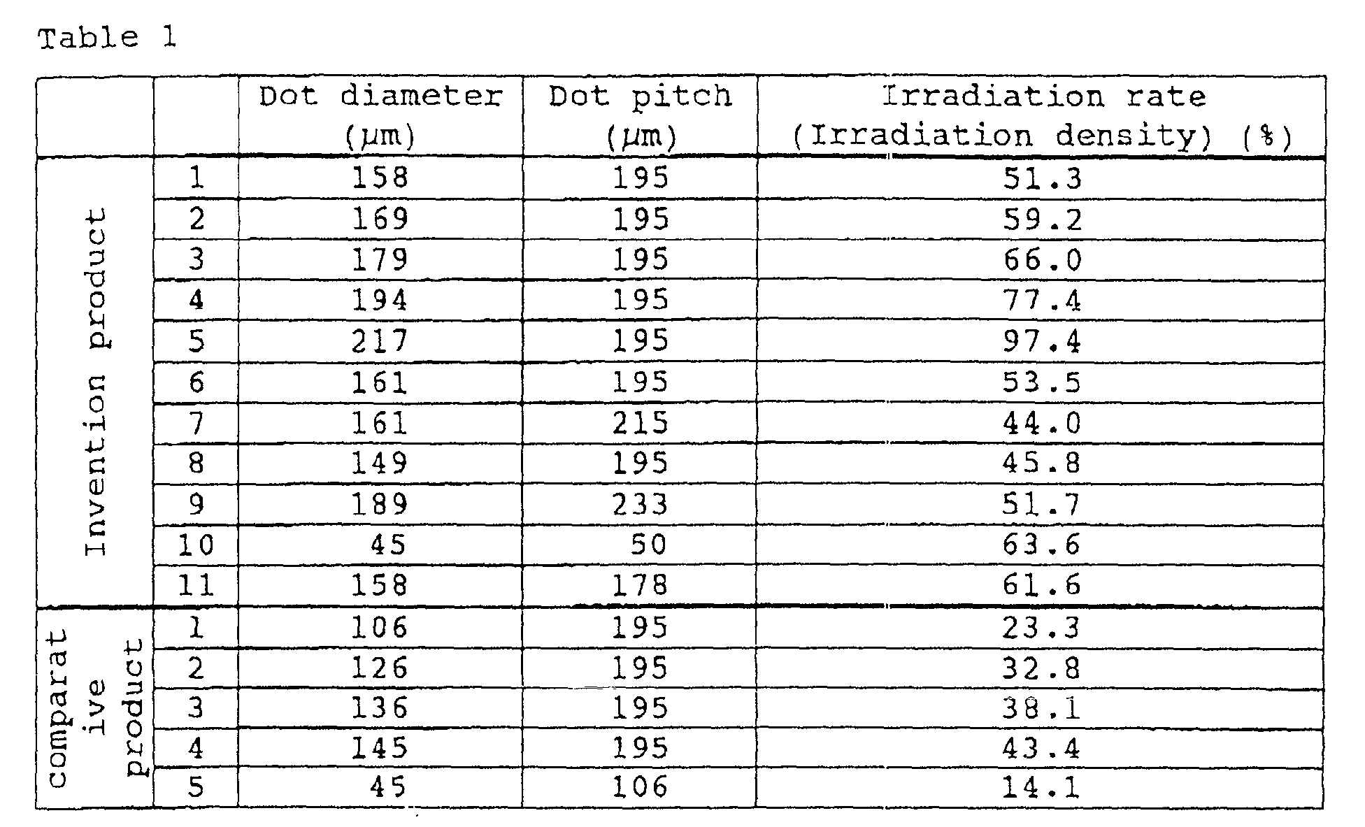
The fluorocarbon resin coated aluminum plane members T1 (50
mm in diameter, 15 µm in coating thickness) were prepared as the
respective test members in Table 1 under different laser irradiation
conditions. However, these test members are manufactured under the
same conditions except for the laser irradiation conditions.
The durability test was conducted on each of the invention
products and the comparative products in Table 1 under the following
test conditions.
Imposed load and time period: the load was imposed in increments
of 500 N up to 5000 N for 50 minutes in total, e.g., a load of 500
N was imposed for 5 minutes, and an additional load of 500 N (i.e.,
1000 N in total) was imposed for 5 minutes.
Rotational frequency: 4000 rpm.
The results of the test under such conditions did not show
seizing in both the product of the invention and the comparative
product. After completing the test up to 5000 N for 5 minutes, the
surface of the member T1, on which the fluorocarbon resin was coated,
was visually inspected to obtain the peeling amount of the coating.
When the peeling amount of the coating was less than that of the
side block of the current product prepared by shot-blasting, it
was judged as good (O). When the peeling amount of the coating was
greater than that of the side block of the current product prepared
by shot-blasting, it was judged as no good (X).
The results of such judgments were plotted in Figs. 6 and 7.
As is evident from Fig. 6 and Fig. 7, the product of the present
invention having an irradiation density (irradiation rate) of 44%
or higher exhibits strong contact and adhesion properties of the
fluorocarbon resin coating layer and an excellent durability. In
the case of the control product having an irradiation density of
less than 44%, the durability cannot be improved.
By the way, as shown in Figs. 6 and 7, the relationship between
the dot diameter d and the dot pitch p should be defined as p ≤
1.336 x d if the irradiation density (irradiation rate) was set
to 44% or higher when the laser irradiation is performed such that
the dots are arranged in a square arrangement in lateral and vertical
directions where the adjacent dots were spaced so as to have equal
pitches p. Furthermore, the relationship between the dot diameter
d and the dot pitch p should be defined as p ≤ 1.436 x d if the
irradiation density (irradiation rate) was set to 44% or more when
the laser irradiation is performed for placing the dots in a triangle
arrangement where the spacing between adjacent dots were equally
spaced so as to have equal staggered pitches P. For increasing the
dot diameter d, there is a need to increase the output of the laser
as shown in Fig. 8.
Thus, in the above invention products 1 to 9 and 11, the YAG
laser was used. The output of the YAG laser can be increased. It
is preferable to effectively perform the laser irradiation for
roughening the substrate of fluorocarbon resin coating on the sliding
surface with a comparatively large area such as the sliding surface
of the side block, which is used under severe sliding conditions
of large loading variation and a high maximum load.
In the above second embodiment using the laser irradiation,
there is an advantage that the surface roughness can be easily adapted
to a desired condition, as compared with the first embodiment that
utilizes shot-blasting. Particularly, the adhesion property can
be increased when the irradiation density (irradiation rate) of
the laser irradiation is set to 44% or higher, so that it can be
applied to a sliding member used under severe usage conditions.
Third Embodiment
Fig. 9 is a flow chart of a method of coating a fluorocarbon
resin according to a third embodiment of the present invention.
In Fig. 9, just as in the case with Fig. 1, the first wash
(101), shot-blasting using a shot material made of sodium bicarbonate
NaHCO3 (102), which is performed to roughen and clean the surface
of the base material, and the second wash (103) are performed in
this order.
subsequently, a plasma irradiation is performed on the base
material from which the shot material is perfectly removed by
roughening and cleaning the surface (904). In the plasma irradiation,
the flow of plasma particles generated from a plasma generator (not
shown) is irradiated on the surface of the base material to be coated
with a fluorocarbon resin coating to roughen the surface by forming
minute atomic-level unevenesses on the surface and simultaneously
activate the surface by the cleaning. The minute atomic-level
unevennesses indicate unevennesses that are finer than those
obtained by the shot-blasting described above.
Consequently the plasma irradiation allows the surface of
the base material to have markedly improved contact and adhesion
properties with respect to the fluorocarbon resin which is made
of a material different from the base material.
After the plasma irradiation, just as in the case with Fig.
1, the fluorocarbon resin coating can be completed through the steps
of fluorocarbon resin coating (106) and baking (107).
After the steps described above, the binding between the
surface of the base material made of an aluminum alloy and the
fluorocarbon resin coated on the surface becomes extremely strong,
so that the fluorocarbon resin coating layer can be prevented from
peeling or detaching from the surface even when a heavy load due
to a strong sliding movement or the like is received.
Furthermore, just as in the case with Fig. 1, there is no shot
material that remains in the base material because the shot material
has completely been drawn off of the base material using a washing
liquid. Therefore, there is no possibility of damaging the sliding
member or the like by the residual shot material flowing into the
inside of the gas compressor in operation.
Consequently, the sliding member coated with the fluorocarbon
resin and the gas compressor having such a sliding member exhibit
an increased durability, an extended life time, and an increased
reliability.
According to the third embodiment of the present invention,
there is no need to perform chemical conversion treatment generally
applied in the conventional method which generates noxious waste
water, to provide large-scale and expensive extra facilities which
are necessary for the chemical conversion treatment. The plasma
irradiation step, which is provided instead of the chemical
conversion treatment, can be easily incorporated in the line
production system. In other words, the coating can be completed
in a consistent manner within one coating treatment line.
Fourth Embodiment
Fig. 10 is a flow chart of a method of coating a fluorocarbon
resin according to a forth embodiment of the present invention.
In Fig. 10, a laser irradiation step (202) is incorporated
instead of the shot-blasting step (102) in Fig. 9. The intensity
of laser light used in the laser irradiation step (202) is of such
a magnitude that the surface of the base material can be slightly
melted and roughened. In addition, pulse laser scans the entire
surface to be irradiated. The irradiation rate of the laser
irradiation is preferably 44% or higher.
The use of laser irradiation has an advantage in that the
condition of the rough surface can be easily adapted to a desired
one, as compared with the case of using the shot-blasting process.
With a plasma irradiation step (904) of Fig. 10, on the surface
of the base material, there are further formed fine atomic-level
unevennesses that are shallower than the recesses formed in the
above laser irradiation step (202).
By such plasma irradiation, the surface of the base member
exhibits markedly improved contact and adhesion properties with
respect to the fluorocarbon resin that is made of a material different
from the base member.
The gas compressor of this invention in which the above side
block 7 is used will be described with reference to Figs. 11 to
14.
Fig. 11 is a vertical sectional view that illustrates a gas
compressor according to an embodiment of the present invention.
Fig. 12 is a cross sectional view taken along the line XII-XII in
Fig. 11, illustrating the interior portion of a cylinder member.
Fig. 13 is a cross sectional view taken along the line XIII- XIII
in Fig. 11, illustrating the surface of the side block on the front
side which makes contact with the cylinder chamber. Fig. 14 is a
cross sectional view taken along the line XIV-XIV in Fig. 11,
illustrating the surface of the side block on the rear side which
makes contact with the cylinder chamber.
The gas compressor of this embodiment is of a well-known
vane-rotary type and is comprised of a head part 2 having a suction
chamber 1, a main part 3 of the compressor into which the gas before
compression is introduced from the suction chamber 1 and compressed,
and a rear part 5 having a discharge chamber 4 where the gas to
be discharged which is compressed by the main part 3 of the compressor
is housed.
The compressor main part 3 comprises a cylinder chamber 8 which
is formed in the inside of a cylinder block 6 and end surfaces thereof
are surrounded with side blocks 7A, 7B. A rotor is rotatably housed
in the cylinder chamber 8. The rotor 9 comprises a plurality of
vanes 10, 10. The tip of each of the vanes 10, 10 can be bounced
in and off while sliding on an inner wall surface 6a of the cylinder
block 6 as the rotor 9 rotates about its rotation axis. The cylinder
chamber 8 is divided into a plurality of compression chambers 11,
11 by being partitioned by the rotor 9 and the vanes 10, 10. The
respective compression chambers 11 inhale the gas from the suction
chamber 1 in succession. Then, the gas is compressed by the rotary
motion of the rotor 9, followed by being discharged into the discharge
chamber 4.
Incidentally, the rotor 9 is designed such that it can be rotated
by a rotary power of an engine shaft (not shown) of the vehicle
through a driving pulley 12, an electromagnetic clutch 13, and a
rotary shaft 14 which are provided in the head part 2. The rotary
shaft 14 is fixed so as to penetrate through the center of each
of the rotor 9 and a coupled driving part 13a of the electromagnetic
clutch 13 and rotatably supported by bearing parts 7j, 7j of the
respective side blocks 7A, 7B.
When the rotor 9 rotates, the tip of the vane 10 and the inner
wall surface 6a of the cylinder block 6 can be slid on each other.
The outer peripheral surface 9a of the rotor 9 and a short diameter
part inner wall surface 6 of the cylinder block 6 can be slid on
each other. In addition, the side surface of a vane groove 9b of
the rotor 9 and the side surface of the vane 10 are slid on each
other. Both end surfaces 9c, 9c of the rotor 9 and the surfaces
7x, 7x of the respective side blocks 7A, 7B which oppose the cylinder
chamber are slid on each other. Furthermore, both end surfaces of
the vane 10 and the surfaces 7x, 7x of the respective side blocks
7A, 7B which oppose the cylinder chamber are slid on each other.
Furthermore, the cylinder block 6, the side blocks 7A, 7B, the rotor
9, and the vane 10 are made of aluminum alloy for weight reduction.
The sliding surface of each of them may be supplied with a
lubricating oil. However, the pressure difference between one
compression chamber 11 and the other compression chamber 11 which
repeat the inhalation of gas and the compression of gas is large.
When a leakage of gas occurs between the compression chambers due
to such a large pressure difference, the efficiency of compression
decreases as the amount of power loss corresponds to the amount
of leakage. Thus, the gap for each sliding surface is designed to
be as small as possible, so that the solid contact can be easily
caused as a lubricating oil film is broken.
Thus, these sliding surfaces may be coated with a fluorocarbon
resin such as polytetrafluoroethylene on one of the sliding surfaces.
Then, the coated surface is faced with the sliding surface of the
opposite aluminum alloy to increase the wear resistance and the
anti-seizing properties.
For preventing the fluorocarbon resin of the compressor in
operation from being peeled or detached, there is a need to securely
contact or adhere an aluminum alloy with the fluorocarbon resin.
For improving the contact and adhesion properties, steps including
the treatment of a base material shown in Fig. 15 have been adapted
as previously explained in the description of prior art.
In this embodiment, for securely contacting and adhering the
coating layers of the sliding surfaces that experience high sliding
load with respect to both side blocks 7A, 7B, the rotor 9 and the
vane 10 in particular, the coating was performed as follows. That
is, polytetrafluoroethylene was coated on the surfaces 7x, 7x of
both the side blocks 7A, 7B which oppose the cylinder chamber, using
the coating method shown in Fig. 1, Fig. 2, Fig. 9, or Fig. 10.
In the surface 7x facing the cylinder chamber, as shown in Figs.
13 and 14, a recessed portion 15, pores, or the like is formed for
application of vane back pressure. Although the coating substrate
treatment such as shot-blasting may also affect surface of such
a recessed portion, pores, or the like, there is no possibility
of generating residual shot-materials, so that the recessed portion,
pores, or the like can be perfectly cleaned in the washing step.
There is no residual shot material generation in both the steps
of using a shot material made of sodium bicarbonate or dry ice as
in Fig. 1 or Fig. 9 and using laser irradiation as in Fig. 2 or
Fig. 10. In addition, each of these steps provides a
polytetrafiuoroethylene coating layer that can be securely contacted
or adhered onto the aluminum alloy, thus allowing its application
to practical use.
When utilizing the step of using the plasma irradiation shown
in Fig. 9 or Fig. 10, the surfaces 7x, 7x of the respective side
blocks 7A, 7B which oppose the cylinder chamber can be finely roughened
and cleaned at an atomic level and activated by means of plasma
irradiation, allowing extremely firm contact or adhesion with
polytetrafluoroethylene.
The fluorocarbon resins which can be used for fluorocarbon
resin coating of the present invention may be a low-molecular weight
ethylene tetrafluoride resin, an ethylene tetrafluoride - propylene
hexafluoride copolymer resin, a vinylidene fluoride resin, an
ethylene chloride trifluoride resin, or the like, in addition to
polytetrafluoroethylene.
In the above embodiments, the step of chemical conversion
treatment or the step of plasma irradiation is performed before
the step of applying fluorocarbon resin. If the application of
fluorocarbon resin can be performed on a sliding part receiving
a comparatively small sliding load or immediately after cleaning
the surface of the base material in the second wash before it becomes
dirty, the step of chemical conversion treatment or plasma
irradiation may be omitted. Since the chemical conversion treatment
requires a specific facility, the omission of the conversion enables
the coating to be completed in a consistent manner within one coating
treatment line.
According to the method of coating a fluorocarbon resin, as
described above, in the substrate treatment of the surface of the
base material to be coated, the surface of the coating target work
piece is subjected to the shot-blasting using a water-soluble shot
material such as sodium bicarbonate or a vaporizable shot material
such as dry ice. The surface of the coating target work piece is
irradiated with the laser light, so that the surface can be roughened
and cleaned to increase the adhesion between the surface and the
fluorocarbon resin coating layer which can be applied on the surface.
Therefore, there is no possibility that the shot material remains
in the base material in the vicinity of the fluorocarbon resin coating
layer. Also, there is no possibility of any damage being caused
to the coating layer or base material by the residual shot member
when it is rubbed against other members.
Furthermore, the contact or adhesion between the base material
and the fluorocarbon resin can be further improved by the addition
of the fine roughening and cleaning step of finely roughening and
cleaning the roughened surface of the base material by means of
plasma irradiation or the like, so that a strong fluorocarbon resin
coating with a high durability and a high reliability can be realized.
Furthermore, since the method of the present invention includes
the steps described below, minute irregularities are formed in the
surface of the coating substrate, so that the fluorocarbon resin
coating can be more securely adhered to the surface of the coating
target work piece and is hardly peeled off. That is, the method
includes the following steps of:
In the laser irradiation step, the proportion of irradiated
dots (rough surface portion) on the substrate can be increased when
the irradiation rate of the laser irradiation is set to 44% or higher.
Thus, the fluorocarbon resin coating can be firmly adhered onto
the surface of the coating target work piece despite the short
irradiation time, so that it does not easily peel off and also can
withstand severe usage conditions.
Furthermore, the plasma irradiation is performed on the surface
of the coating target work piece in the substrate treatment step
to clean the surface of the target while finely roughening such
a surface at an atomic level to activate the surface. Therefore,
the fluorocarbon resin can be coated on the surface having thus
enhanced contact and adhesion properties. In other words, the
chemical conversion treatment which has been required in the
conventional method is not required in the present invention, so
that there is no need to provide any waste water processing facilities
for processing noxious waster water that is generated in the chemical
conversion treatment. Therefore, dramatic cost reduction can be
realized. Also, the fear of environmental pollution occurring due
to leakage of the waste water or the like can be completely eliminated.
The plasma irradiation step can be incorporated into the
fluorocarbon resin coating step, thus enabling a drastic increase
in production efficiency.
Therefore, the life time of each of the sliding member having
the sliding surface coated with the fluorocarbon resin coating and
the gas compressor having such a sliding member having the sliding
surface coated with the fluorocarbon resin coating can be extended
to realize enhanced reliability.